EP0643987A2 - Désulfuration de gaz de fumée à régénération biologique - Google Patents
Désulfuration de gaz de fumée à régénération biologique Download PDFInfo
- Publication number
- EP0643987A2 EP0643987A2 EP94305046A EP94305046A EP0643987A2 EP 0643987 A2 EP0643987 A2 EP 0643987A2 EP 94305046 A EP94305046 A EP 94305046A EP 94305046 A EP94305046 A EP 94305046A EP 0643987 A2 EP0643987 A2 EP 0643987A2
- Authority
- EP
- European Patent Office
- Prior art keywords
- reagent
- flue gas
- sulphur
- digester reactor
- digester
- Prior art date
- Legal status (The legal status is an assumption and is not a legal conclusion. Google has not performed a legal analysis and makes no representation as to the accuracy of the status listed.)
- Granted
Links
- UGFAIRIUMAVXCW-UHFFFAOYSA-N Carbon monoxide Chemical compound [O+]#[C-] UGFAIRIUMAVXCW-UHFFFAOYSA-N 0.000 title claims abstract description 66
- 239000003546 flue gas Substances 0.000 title claims abstract description 62
- 239000003153 chemical reaction reagent Substances 0.000 claims abstract description 58
- 239000006096 absorbing agent Substances 0.000 claims abstract description 26
- 239000007789 gas Substances 0.000 claims abstract description 24
- 239000010802 sludge Substances 0.000 claims abstract description 23
- XLYOFNOQVPJJNP-UHFFFAOYSA-N water Substances O XLYOFNOQVPJJNP-UHFFFAOYSA-N 0.000 claims abstract description 23
- 241000894006 Bacteria Species 0.000 claims abstract description 21
- 238000006243 chemical reaction Methods 0.000 claims abstract description 20
- NINIDFKCEFEMDL-UHFFFAOYSA-N Sulfur Chemical compound [S] NINIDFKCEFEMDL-UHFFFAOYSA-N 0.000 claims abstract description 16
- 239000005864 Sulphur Substances 0.000 claims abstract description 16
- 235000015097 nutrients Nutrition 0.000 claims abstract description 13
- 230000001580 bacterial effect Effects 0.000 claims abstract description 11
- 239000007787 solid Substances 0.000 claims abstract description 9
- 239000010815 organic waste Substances 0.000 claims abstract description 6
- QVGXLLKOCUKJST-UHFFFAOYSA-N atomic oxygen Chemical compound [O] QVGXLLKOCUKJST-UHFFFAOYSA-N 0.000 claims abstract description 5
- 239000001301 oxygen Substances 0.000 claims abstract description 5
- 229910052760 oxygen Inorganic materials 0.000 claims abstract description 5
- RAHZWNYVWXNFOC-UHFFFAOYSA-N Sulphur dioxide Chemical compound O=S=O RAHZWNYVWXNFOC-UHFFFAOYSA-N 0.000 claims description 54
- 238000000034 method Methods 0.000 claims description 36
- 239000004291 sulphur dioxide Substances 0.000 claims description 27
- 235000010269 sulphur dioxide Nutrition 0.000 claims description 27
- 238000010521 absorption reaction Methods 0.000 claims description 12
- 230000001172 regenerating effect Effects 0.000 claims description 7
- 230000008929 regeneration Effects 0.000 claims description 7
- 238000011069 regeneration method Methods 0.000 claims description 7
- QAOWNCQODCNURD-UHFFFAOYSA-N Sulfuric acid Chemical compound OS(O)(=O)=O QAOWNCQODCNURD-UHFFFAOYSA-N 0.000 claims description 6
- 235000011149 sulphuric acid Nutrition 0.000 claims description 6
- 239000001117 sulphuric acid Substances 0.000 claims description 4
- 235000021049 nutrient content Nutrition 0.000 claims 2
- 239000010841 municipal wastewater Substances 0.000 abstract description 5
- 238000004065 wastewater treatment Methods 0.000 abstract description 5
- 235000019738 Limestone Nutrition 0.000 description 15
- 239000006028 limestone Substances 0.000 description 15
- 239000002002 slurry Substances 0.000 description 14
- GEHJYWRUCIMESM-UHFFFAOYSA-L sodium sulfite Chemical compound [Na+].[Na+].[O-]S([O-])=O GEHJYWRUCIMESM-UHFFFAOYSA-L 0.000 description 13
- CDBYLPFSWZWCQE-UHFFFAOYSA-L Sodium Carbonate Chemical compound [Na+].[Na+].[O-]C([O-])=O CDBYLPFSWZWCQE-UHFFFAOYSA-L 0.000 description 11
- 238000010586 diagram Methods 0.000 description 10
- 239000000047 product Substances 0.000 description 8
- 235000010265 sodium sulphite Nutrition 0.000 description 7
- DWAQJAXMDSEUJJ-UHFFFAOYSA-M Sodium bisulfite Chemical compound [Na+].OS([O-])=O DWAQJAXMDSEUJJ-UHFFFAOYSA-M 0.000 description 6
- HEMHJVSKTPXQMS-UHFFFAOYSA-M Sodium hydroxide Chemical compound [OH-].[Na+] HEMHJVSKTPXQMS-UHFFFAOYSA-M 0.000 description 6
- 239000003513 alkali Substances 0.000 description 6
- OSGAYBCDTDRGGQ-UHFFFAOYSA-L calcium sulfate Chemical compound [Ca+2].[O-]S([O-])(=O)=O OSGAYBCDTDRGGQ-UHFFFAOYSA-L 0.000 description 6
- 229910000029 sodium carbonate Inorganic materials 0.000 description 6
- 235000010267 sodium hydrogen sulphite Nutrition 0.000 description 6
- QTBSBXVTEAMEQO-UHFFFAOYSA-N Acetic acid Chemical compound CC(O)=O QTBSBXVTEAMEQO-UHFFFAOYSA-N 0.000 description 5
- 239000006227 byproduct Substances 0.000 description 5
- 239000003245 coal Substances 0.000 description 5
- 235000017550 sodium carbonate Nutrition 0.000 description 5
- VTYYLEPIZMXCLO-UHFFFAOYSA-L Calcium carbonate Chemical compound [Ca+2].[O-]C([O-])=O VTYYLEPIZMXCLO-UHFFFAOYSA-L 0.000 description 4
- 235000010261 calcium sulphite Nutrition 0.000 description 4
- 238000002485 combustion reaction Methods 0.000 description 4
- 239000010881 fly ash Substances 0.000 description 4
- 239000004289 sodium hydrogen sulphite Substances 0.000 description 4
- AKEJUJNQAAGONA-UHFFFAOYSA-N sulfur trioxide Chemical compound O=S(=O)=O AKEJUJNQAAGONA-UHFFFAOYSA-N 0.000 description 4
- OYPRJOBELJOOCE-UHFFFAOYSA-N Calcium Chemical compound [Ca] OYPRJOBELJOOCE-UHFFFAOYSA-N 0.000 description 3
- 235000008733 Citrus aurantifolia Nutrition 0.000 description 3
- 235000011941 Tilia x europaea Nutrition 0.000 description 3
- 239000011575 calcium Substances 0.000 description 3
- 229910052791 calcium Inorganic materials 0.000 description 3
- 239000000446 fuel Substances 0.000 description 3
- 239000004571 lime Substances 0.000 description 3
- VTHJTEIRLNZDEV-UHFFFAOYSA-L magnesium dihydroxide Chemical compound [OH-].[OH-].[Mg+2] VTHJTEIRLNZDEV-UHFFFAOYSA-L 0.000 description 3
- 239000000347 magnesium hydroxide Substances 0.000 description 3
- 235000012254 magnesium hydroxide Nutrition 0.000 description 3
- 229910001862 magnesium hydroxide Inorganic materials 0.000 description 3
- 239000012716 precipitator Substances 0.000 description 3
- CSNNHWWHGAXBCP-UHFFFAOYSA-L Magnesium sulfate Chemical compound [Mg+2].[O-][S+2]([O-])([O-])[O-] CSNNHWWHGAXBCP-UHFFFAOYSA-L 0.000 description 2
- 235000011054 acetic acid Nutrition 0.000 description 2
- 229910000020 calcium bicarbonate Inorganic materials 0.000 description 2
- 229910000019 calcium carbonate Inorganic materials 0.000 description 2
- GBAOBIBJACZTNA-UHFFFAOYSA-L calcium sulfite Chemical compound [Ca+2].[O-]S([O-])=O GBAOBIBJACZTNA-UHFFFAOYSA-L 0.000 description 2
- 239000001175 calcium sulphate Substances 0.000 description 2
- 235000011132 calcium sulphate Nutrition 0.000 description 2
- 239000004295 calcium sulphite Substances 0.000 description 2
- 239000002803 fossil fuel Substances 0.000 description 2
- 238000004519 manufacturing process Methods 0.000 description 2
- 239000000203 mixture Substances 0.000 description 2
- 238000003860 storage Methods 0.000 description 2
- 239000002562 thickening agent Substances 0.000 description 2
- 239000002699 waste material Substances 0.000 description 2
- 238000005200 wet scrubbing Methods 0.000 description 2
- KRKNYBCHXYNGOX-UHFFFAOYSA-K Citrate Chemical compound [O-]C(=O)CC(O)(CC([O-])=O)C([O-])=O KRKNYBCHXYNGOX-UHFFFAOYSA-K 0.000 description 1
- DGAQECJNVWCQMB-PUAWFVPOSA-M Ilexoside XXIX Chemical compound C[C@@H]1CC[C@@]2(CC[C@@]3(C(=CC[C@H]4[C@]3(CC[C@@H]5[C@@]4(CC[C@@H](C5(C)C)OS(=O)(=O)[O-])C)C)[C@@H]2[C@]1(C)O)C)C(=O)O[C@H]6[C@@H]([C@H]([C@@H]([C@H](O6)CO)O)O)O.[Na+] DGAQECJNVWCQMB-PUAWFVPOSA-M 0.000 description 1
- QAOWNCQODCNURD-UHFFFAOYSA-L Sulfate Chemical compound [O-]S([O-])(=O)=O QAOWNCQODCNURD-UHFFFAOYSA-L 0.000 description 1
- 150000001243 acetic acids Chemical class 0.000 description 1
- 239000002253 acid Substances 0.000 description 1
- 239000012080 ambient air Substances 0.000 description 1
- 150000001412 amines Chemical class 0.000 description 1
- 239000003139 biocide Substances 0.000 description 1
- 230000015572 biosynthetic process Effects 0.000 description 1
- 238000001354 calcination Methods 0.000 description 1
- NKWPZUCBCARRDP-UHFFFAOYSA-L calcium bicarbonate Chemical compound [Ca+2].OC([O-])=O.OC([O-])=O NKWPZUCBCARRDP-UHFFFAOYSA-L 0.000 description 1
- 239000007795 chemical reaction product Substances 0.000 description 1
- 239000003638 chemical reducing agent Substances 0.000 description 1
- 150000003841 chloride salts Chemical class 0.000 description 1
- 238000004140 cleaning Methods 0.000 description 1
- 150000001875 compounds Chemical class 0.000 description 1
- 239000000356 contaminant Substances 0.000 description 1
- 230000008030 elimination Effects 0.000 description 1
- 238000003379 elimination reaction Methods 0.000 description 1
- 230000007613 environmental effect Effects 0.000 description 1
- 239000012530 fluid Substances 0.000 description 1
- 239000013505 freshwater Substances 0.000 description 1
- 239000007788 liquid Substances 0.000 description 1
- 229910052943 magnesium sulfate Inorganic materials 0.000 description 1
- 235000019341 magnesium sulphate Nutrition 0.000 description 1
- 239000000463 material Substances 0.000 description 1
- 230000002503 metabolic effect Effects 0.000 description 1
- 230000000813 microbial effect Effects 0.000 description 1
- 238000002156 mixing Methods 0.000 description 1
- 238000001139 pH measurement Methods 0.000 description 1
- 238000002360 preparation method Methods 0.000 description 1
- 230000001737 promoting effect Effects 0.000 description 1
- 238000011084 recovery Methods 0.000 description 1
- 238000011946 reduction process Methods 0.000 description 1
- 238000003303 reheating Methods 0.000 description 1
- 150000003839 salts Chemical class 0.000 description 1
- 238000005201 scrubbing Methods 0.000 description 1
- 238000000926 separation method Methods 0.000 description 1
- 239000011734 sodium Substances 0.000 description 1
- 229910052708 sodium Inorganic materials 0.000 description 1
- 239000012265 solid product Substances 0.000 description 1
- LSNNMFCWUKXFEE-UHFFFAOYSA-L sulfite Chemical compound [O-]S([O-])=O LSNNMFCWUKXFEE-UHFFFAOYSA-L 0.000 description 1
- 150000003467 sulfuric acid derivatives Chemical class 0.000 description 1
- 229910021653 sulphate ion Inorganic materials 0.000 description 1
- 231100000331 toxic Toxicity 0.000 description 1
- 230000002588 toxic effect Effects 0.000 description 1
Images


Classifications
-
- B—PERFORMING OPERATIONS; TRANSPORTING
- B01—PHYSICAL OR CHEMICAL PROCESSES OR APPARATUS IN GENERAL
- B01D—SEPARATION
- B01D53/00—Separation of gases or vapours; Recovering vapours of volatile solvents from gases; Chemical or biological purification of waste gases, e.g. engine exhaust gases, smoke, fumes, flue gases, aerosols
- B01D53/34—Chemical or biological purification of waste gases
- B01D53/74—General processes for purification of waste gases; Apparatus or devices specially adapted therefor
- B01D53/84—Biological processes
-
- B—PERFORMING OPERATIONS; TRANSPORTING
- B01—PHYSICAL OR CHEMICAL PROCESSES OR APPARATUS IN GENERAL
- B01D—SEPARATION
- B01D53/00—Separation of gases or vapours; Recovering vapours of volatile solvents from gases; Chemical or biological purification of waste gases, e.g. engine exhaust gases, smoke, fumes, flue gases, aerosols
- B01D53/34—Chemical or biological purification of waste gases
- B01D53/46—Removing components of defined structure
- B01D53/48—Sulfur compounds
- B01D53/50—Sulfur oxides
- B01D53/501—Sulfur oxides by treating the gases with a solution or a suspension of an alkali or earth-alkali or ammonium compound
- B01D53/502—Sulfur oxides by treating the gases with a solution or a suspension of an alkali or earth-alkali or ammonium compound characterised by a specific solution or suspension
-
- Y—GENERAL TAGGING OF NEW TECHNOLOGICAL DEVELOPMENTS; GENERAL TAGGING OF CROSS-SECTIONAL TECHNOLOGIES SPANNING OVER SEVERAL SECTIONS OF THE IPC; TECHNICAL SUBJECTS COVERED BY FORMER USPC CROSS-REFERENCE ART COLLECTIONS [XRACs] AND DIGESTS
- Y02—TECHNOLOGIES OR APPLICATIONS FOR MITIGATION OR ADAPTATION AGAINST CLIMATE CHANGE
- Y02A—TECHNOLOGIES FOR ADAPTATION TO CLIMATE CHANGE
- Y02A50/00—TECHNOLOGIES FOR ADAPTATION TO CLIMATE CHANGE in human health protection, e.g. against extreme weather
- Y02A50/20—Air quality improvement or preservation, e.g. vehicle emission control or emission reduction by using catalytic converters
Definitions
- the present invention relates in general to systems and methods for flue gas desulphurization (FGD) and, in particular, to such systems and methods using a regenerative reagent produced by biological means.
- FGD flue gas desulphurization
- regeneratorable reagent processes for the desulphurization of flue gas include sodium based systems and processes such as the Wellman-Lord process, the Citrate process, Amine-based processes, and the MgO process.
- Wet regenerable FGD processes generally include an absorption step in which fresh or regenerated reagent is reacted with SO2 in a scrubber to clean and desulphurize the flue gas.
- the SO2 absorption reaction produces products which are sent to a regeneration system which generally requires the addition of heat in order to produce an SO2 rich gas.
- This SO2 rich gas is then further treated to produce sulphur, sulphuric acid, or liquid SO2.
- the reagent used during the absorption process is then regenerated for further use in the SO2 absorption process.
- the reactions involved in the SO2 absorption and stripping processes are very complex. Because of their complexity, these reactions require a great amount of energy to proceed to completion.
- FIG. 1 of the accompanying drawings is a simplified schematic diagram of a known regenerable wet flue gas desulphurization system 10 which employs the Wellman-Lord process.
- flue gas 12 from a boiler or combustor 14 is provided to a prescrubber 16 to remove flyash and chlorides.
- the flyash is collected in a water slurry 18 that is transported to a settling pond 20 before discharge.
- Prescrubbed flue gas 22 is directed to an absorber 24 for removal of sulphur dioxide (SO2).
- a sodium sulphite (Na2SO3) solution 26 is provided from a make up tank 28 to the absorber 24 for this purpose.
- Cleaned, saturated flue gas 30 leaves the absorber 24 and is sent to a reheater 32 prior to discharge into the atmosphere via a stack 34.
- Steam 36 may be used to accomplish this reheating step.
- the sodium sulphite is converted to sodium bisulphite (NaHS03) 38 which is sent to a regenerator 40.
- NaHS03 sodium bisulphite
- the regenerator 40 includes an evaporator crystallizer.
- the SO2 vapour is removed at 44 from the regenerator 40 for sulphur recovery.
- a regenerated solution 46 consisting of sodium sulphite is taken from the regenerator 40 and enters the make up tank 28 where sodium carbonate/sodium hydroxide (Na2C03/NaOH) is added by a stream 48.
- FIG 2 is a simplified schematic diagram of another known wet regenerable flue gas desulphurization system 50 which employs the MgO wet scrubbing process.
- the simplified reactions in an MgO scrubber are as follows: Mg(OH2) + SO 2(g) ⁇ MgSO3 + H2O (absorption)
- flue gas 12 and water 52 are provided to a quencher 54.
- the cooled flue gas 56 is provided to a scrubber 58 which also receives an Mg(OH)2 slurry 60 provided by a slaker 62.
- the scrubber 58 produces a solution 64 of MgSO3, MgSO4, and water, H2O.
- Some of the solution 64 is recirculated along with the Mg(OH)2 slurry 60 and the rest is provided to a dewatering means 66.
- MgO 68 is provided to the slaker 62 partly recycled from a calciner 70 to produce the Mg(OH)2 slurry 60.
- Water 52 is mixed with a solution 72 from the dewatering means 66 to form a solution 74 which is provided to the slaker 62.
- a by-product solution 76 from the dewatering means 66 is provided to a dryer 78 along with fuel 80 to dry the solution 76.
- the now dry material 82 is provided to the calciner 70 along with fuel 80 to produce the MgO 68.
- the SO2 84 generated from the calciner 70 is provided to an acid plant 86 to produce H2SO4 88. Cleaned, desulphurized flue gas leaves the scrubber 58 at 90.
- FIG. 3 Shown in Figure 3 is a simplified schematic diagram of such a known wet regenerable flue gas desulphurization system 100 which employs a dual-alkali (limestone) process.
- Flue gas 12 is provided to a precipitator 102 for removal of flyash 104 from the flue gas 12.
- the cleaned flue gas 106 from the precipitator 102 enters an absorber 108 for producing a cleaned and desulphurized flue gas 110 which is provided to a stack 34.
- the absorber 108 receives a sodium sulphite solution 112 which is used as the reagent to remove the SO2 from the flue gas 106.
- a sodium bisulphite (NaHSO3) solution 114 is created during SO2 absorption, and this solution 114 is sent to a reaction tank 116 where it is mixed with a limestone slurry 118.
- the reaction tank 116 comprises the regeneration portion of this known dual-alkali (limestone) flue gas desulphurization system.
- Crushed limestone 120 is mixed with water 52 in a ball mill 122 to produce the limestone slurry 118.
- the limestone slurry 118 is stored in a limestone slurry tank 124 for use as required by the process.
- Soda ash 126 is provided along with water 52 to a surge tank 128.
- a thickener 130 is used to thicken a suspended solid product or sludge 132 from the reaction tank 116. This thickened product 134 is, in turn, provided to the filter 136.
- the recovered water 131 overflows from the thickener 130 into the surge tank 128, where it is mixed with soda ash 126, and is used as make-up for soda losses and water to produce sodium sulphite solution 112.
- the thickened product 134 is then provided to a filter 136 along with water 52 used to wash the thickened product 134.
- Fly ash 104 from the precipitator 102 is combined with lime 138 and the washed, thickened product from the filter 136 in a mixer 140, and the entire mixture is eventually disposed of in a land-fill 142.
- a common problem in all dual-alkali processes is that a sludge is produced as a byproduct of this reaction that must be either land-filled or converted into a useful form.
- non-regenerated flue gas desulphurization systems that are calcium based have been used for desulphurization purposes.
- lime or limestone or another reagent is also reacted with SO2.
- the end product of this reaction is also a sludge similar to the sludge produced by the dual-alkali systems which must be disposed or converted into a useful form.
- FIG 4 is a simplified schematic diagram of such a typical flue gas desulphurization system 150, specifically a non-regenerable throwaway system.
- Flue gas 12 is delivered to an absorber 152 to produce a clean flue gas 153 which is provided to a stack 34.
- Crushed limestone 154 and water 52 are provided to a ball mill 156 where the limestone 154 is finely ground to produce a limestone slurry 158.
- the limestone slurry 158 is stored for use as required, in a storage tank 160.
- the limestone slurry 158 is provided to the absorber 152 where it reacts with the SO2 in the flue gas 12 to produce a slurry 162 of primarily calcium sulphite (CaSO3) and calcium sulphate (CaSO4).
- CaSO3 calcium sulphite
- CaSO4 calcium sulphate
- This slurry 162 is recirculated back to an upper portion of the absorber 152 by a pump 164 to further promote SO2 absorption. A portion of the slurry 162 is also sent to a pond 166 for disposal. Other alternatives exist for sludge processing and disposal. Water 168 can be returned from the pond 166 and mixed in a blend station 170 with fresh water 52 and used in the absorber 152 as make-up water.
- Naturally occurring sulphur-reducing bacteria are known to exist. These bacteria are known to oxidize organics to acetic acids which, in turn, produce H2S through metabolic reduction from scrubber sludge.
- One known reaction is as follows: CH3COOH + SO42 ⁇ (SO32 ⁇ ) ⁇ H2S + 2HCO3 ⁇
- sulphur-reducing bacteria from either the Disulfovibrio genus or the Disulfotomaculum genus
- FGD sludge processing and storage areas At present, there has been no known system or method for using sulphur-reducing bacteria from FGD waste sludge after the desulphurization process of the flue gas.
- a preferred embodiment of the present invention provides a method and system for desulphurization of flue gas using a regenerated reagent produced by sulphur-reducing bacteria.
- a nutrient source such as that commonly found in the organic waste sludge from municipal waste water treatment plants can be used when necessary in order to maximize bacterial growth.
- the preferred embodiment uses an absorber for receiving flue gas, reagent and water for absorbing sulphur or SO2 from the flue gas.
- the spent reagent is provided to a digester reactor.
- Sulphur-reducing bacteria contained within the digester reactor react with the spent reagent and regenerate it.
- Gases produced by the reactions in the digester reactor can be collected by a gas collector.
- H2S rich gas collected by the gas collector is provided to a final processor.
- a nutrient source such as organic waste sludge from municipal waste water treatment plants can be used to maximize bacterial growth and thus H2S gas production and reagent regeneration.
- a separator can be used to separate the regenerated reagent from the organic solids bacterial sludge in the digester reactor.
- the sludge can then be provided to an organic sludge processor while the regenerated reagent is provided back into the absorber for further reaction with the flue gas.
- one aspect of the preferred embodiment of the present invention is the use of a waste stream such as sludge from a municipal waste water treatment plant to maximize bacterial growth and increase the rate of H2S formation and reagent regeneration.
- the preferred method and system for desulphurizing flue gas is efficient and cost effective.
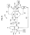
- FIG. 5 is a simplified schematic diagram of a bioregenerative flue gas desulphurization (FGD) system 200 according to an embodiment of the present invention.
- the bioregenerative FGD system 200 receives flue gas 12 produced during the combustion of fossil fuels such as oil or coal. or refuse fuels.
- the flue gas 12 is provided to an absorber tower or module 202 for SO2 absorption, along with reagent 204 and water 52.
- the water 52 can be provided from a source 206.
- the spent reagent 208 is provided to a digester reactor 210.
- Sulphur-reducing bacteria in the digester reactor 210 cause the evolution of H2S from the spent reagent 208 which yields a product 212 containing both regenerated reagent and organic solids.
- Gases produced by reactions occurring within the digester 210 are collected in a gas collector 214.
- the gas collector 214 can be used to collect by-product H2S-rich gas 216 which can be processed in a final processor 218.
- a separator 220 is used to separate the product 212 produced by reactions occurring in the digester reactor 210 from the spent reagent 208. This separation process produces an organic solids sludge 222 and regenerated reagent 224.
- the sludge 222 separated by the separator 220 is provided to a sludge processor 226 and/or returned to the digester reactor 210.
- the regenerated reagent 224 separated from the sludge 222 in the separator 220 is provided back into the absorber 202 for further reaction with the flue gas 12.
- a nutrient source 228 is provided as necessary to the digester reactor 210 to promote bacterial growth therein.
- the system 200 thus provides a bioregenerative flue gas desulphurization process that utilizes sulphur-reducing bacteria as a reducing agent to regenerate the reagent 204 used to desulphurize the flue gas 12.
- sulphur-reducing bacteria as a reducing agent
- the bacteria are used to convert calcium/sulphur (SO42 ⁇ or SO32 ⁇ ) salts to calcium carbonate (CaCO3) or calcium bicarbonate (Ca(HCO3)2) which can be physically separated from the organic solids sludge 222 as the regenerated reagent 224 for reuse in the system 200.
- the system also produces the by-product H2S gas 216 which can be burned in the processor 218 in order to from an SO2-rich gas stream to produce SO2, or reacted to produce sulphur through a Claus reaction. Additionally, sulphuric acid (H2SO4) can also be produced from this by-product H2S gas 216.
- H2SO4 sulphuric acid
- the system 200 provides for the promotion of bacterial growth by addition of the nutrient from the source 228 and by controlling environmental conditions such as temperature, pH and oxygen content, within the digester reactor 210.
- environmental conditions such as temperature, pH and oxygen content
- the optimum ranges of these parameters will depend upon the particular strain of sulphur-reducing bacteria used in the digester reactor 210. It is preferred that the sulphur-reducing bacteria be of the Disulfovibrio genus or the Disulfotomaculum genus.
- Suitable temperature sensing means 230, pH sensing means 232, and oxygen sensing means 234 are provided for this purpose, along with nutrient flow rate sensing means 236, nutrient flow control means 238 and valve means 240.
- the nutrient source 228 is preferably an organic waste sludge of the type which can be commonly found in municipal waste water treatment plants in order to maximize bacterial growth. By promoting bacterial growth and selecting the most suitable bacteria, the size of the digester reactor 210 can be optimized for any particular application.
- the digester reactor 210 can be a single tank or plurality of tanks having a sufficient volume in order to allow the microbial reduction of the spent reagent 208 to occur.
- the reduction process occurring in the digester reactor 210 can be performed in either batch or continuous modes.
- the gas collector 214 can comprise a fluid, chamber, lid or bladder which can trap any released gases, including H2S, without significant mixing with ambient air.
- the digester reactor 210 and gas collector 214 may replace evaporators which are commonly found in previously-proposed systems for the regeneration of reagent. By eliminating the need for such evaporators, the need for steam stripping and calcinating steps and their associated equipment is eliminated, together with the great energy demand required by these steps. Great savings in power consumption can thus be achieved, savings which are not available in known regenerable systems.
- the present system provides for a substantial reduction in the make-up requirements for the reagent 204 used in the system 200. Effective elimination of reagent handling and preparation equipment can be achieved, except for small tanks and/or silos for the reagent 204. Thus substantial savings in capital equipment and operating costs may be achieved.
- the present system replaces complicated and expensive equipment such a steam strippers, multi-stage evaporators, dryers and calciners through the use of compact tanks or vessels for biological sulphur reduction.
Landscapes
- Engineering & Computer Science (AREA)
- Chemical & Material Sciences (AREA)
- Biomedical Technology (AREA)
- Health & Medical Sciences (AREA)
- Environmental & Geological Engineering (AREA)
- Analytical Chemistry (AREA)
- General Chemical & Material Sciences (AREA)
- Oil, Petroleum & Natural Gas (AREA)
- Chemical Kinetics & Catalysis (AREA)
- Molecular Biology (AREA)
- Life Sciences & Earth Sciences (AREA)
- Treating Waste Gases (AREA)
- Processing Of Solid Wastes (AREA)
- Treatment Of Sludge (AREA)
- Micro-Organisms Or Cultivation Processes Thereof (AREA)
Applications Claiming Priority (2)
| Application Number | Priority Date | Filing Date | Title |
|---|---|---|---|
| US12432493A | 1993-09-20 | 1993-09-20 | |
| US124324 | 1993-09-20 |
Publications (3)
| Publication Number | Publication Date |
|---|---|
| EP0643987A2 true EP0643987A2 (fr) | 1995-03-22 |
| EP0643987A3 EP0643987A3 (fr) | 1995-03-29 |
| EP0643987B1 EP0643987B1 (fr) | 1998-01-14 |
Family
ID=22414199
Family Applications (1)
| Application Number | Title | Priority Date | Filing Date |
|---|---|---|---|
| EP94305046A Revoked EP0643987B1 (fr) | 1993-09-20 | 1994-07-08 | Désulfuration de gaz de fumée à régénération biologique |
Country Status (5)
| Country | Link |
|---|---|
| EP (1) | EP0643987B1 (fr) |
| JP (1) | JPH07108134A (fr) |
| CA (1) | CA2132372A1 (fr) |
| DE (1) | DE69407905T2 (fr) |
| ES (1) | ES2111250T3 (fr) |
Cited By (3)
| Publication number | Priority date | Publication date | Assignee | Title |
|---|---|---|---|---|
| NL1008407C2 (nl) * | 1998-02-25 | 1999-08-26 | Hoogovens Tech Services | Werkwijze en inrichting voor het reinigen van een gas. |
| CN101543719B (zh) * | 2009-03-24 | 2011-10-05 | 中电投远达环保工程有限公司 | 双相整流烟气脱硫系统辅助设计系统 |
| CN108192678A (zh) * | 2018-01-24 | 2018-06-22 | 青岛利德恒业机械有限公司 | 一种沼气生物脱硫工艺 |
Family Cites Families (5)
| Publication number | Priority date | Publication date | Assignee | Title |
|---|---|---|---|---|
| DE3621333C2 (de) * | 1986-06-26 | 1995-07-06 | Zueblin Ag | Verfahren zum Abbau von Abfall-Gips |
| FR2625918B1 (fr) * | 1988-01-18 | 1990-06-08 | Bertin & Cie | Procede et installation d'epuration d'effluents gazeux contenant de l'anhydride sulfureux et eventuellement des oxydes d'azote |
| NL9000876A (nl) * | 1990-04-12 | 1991-11-01 | Pacques Bv | Werkwijze voor het verwijderen van zwavelverbindingen uit water. |
| NL9002661A (nl) * | 1990-12-04 | 1992-07-01 | Pacques Bv | Werkwijze voor de verwijdering van h2s uit gas. |
| CA2138271A1 (fr) * | 1992-03-25 | 1993-09-30 | Dolloff F. Bishop | Utilisation de films fixes |
-
1994
- 1994-07-08 ES ES94305046T patent/ES2111250T3/es not_active Expired - Lifetime
- 1994-07-08 EP EP94305046A patent/EP0643987B1/fr not_active Revoked
- 1994-07-08 DE DE69407905T patent/DE69407905T2/de not_active Revoked
- 1994-09-19 CA CA002132372A patent/CA2132372A1/fr not_active Abandoned
- 1994-09-19 JP JP6248274A patent/JPH07108134A/ja not_active Withdrawn
Cited By (3)
| Publication number | Priority date | Publication date | Assignee | Title |
|---|---|---|---|---|
| NL1008407C2 (nl) * | 1998-02-25 | 1999-08-26 | Hoogovens Tech Services | Werkwijze en inrichting voor het reinigen van een gas. |
| CN101543719B (zh) * | 2009-03-24 | 2011-10-05 | 中电投远达环保工程有限公司 | 双相整流烟气脱硫系统辅助设计系统 |
| CN108192678A (zh) * | 2018-01-24 | 2018-06-22 | 青岛利德恒业机械有限公司 | 一种沼气生物脱硫工艺 |
Also Published As
| Publication number | Publication date |
|---|---|
| CA2132372A1 (fr) | 1995-03-21 |
| DE69407905D1 (de) | 1998-02-19 |
| EP0643987A3 (fr) | 1995-03-29 |
| EP0643987B1 (fr) | 1998-01-14 |
| DE69407905T2 (de) | 1998-04-30 |
| JPH07108134A (ja) | 1995-04-25 |
| ES2111250T3 (es) | 1998-03-01 |
Similar Documents
| Publication | Publication Date | Title |
|---|---|---|
| US5100633A (en) | Method for scrubbing pollutants from an exhaust gas stream | |
| EP0487102B1 (fr) | Système pour la récupération et utilisation de gaz CO2 | |
| US4452766A (en) | Double alkali process for removal of sulfur dioxide from gas streams | |
| US5624649A (en) | Process for reduction of sulfur dioxide emission from combustion gases combined with production of potassium sulfate | |
| CA2629987C (fr) | Procede de desulfurisation des gaz de combustion faisant appel au peroxyde d'hydrogene | |
| DK2734283T3 (en) | PROCESS FOR REMOVING IMPURITIES FROM flue gas condensate | |
| US3944649A (en) | Multistage process for removing sulfur dioxide from stack gases | |
| US4859440A (en) | Method of treating flue gases and combustion residues | |
| EP3950096A1 (fr) | Dispositif et procédé concernant un traitement de purification de gaz et/ou un traitement de neutralisation de cendres de combustion | |
| JPH0255095B2 (fr) | ||
| EP2221101B1 (fr) | Procédé d'adoucissement de l'eau à utiliser dans un épurateur-laveur | |
| EP0066707B1 (fr) | Procédé pour limiter l'accumulation de chloride dans une bouillie d'un laveur de SO2 | |
| CN103585869A (zh) | 碱吸收液可循环利用的烟气净化方法 | |
| WO2021193476A1 (fr) | Dispositif et procédé se rapportant au traitement de purification de gaz d'échappement de combustion | |
| EP0097240B1 (fr) | Procédé d'élimination des oxides de soufre de gaz chauds | |
| JPH0741309A (ja) | 二酸化硫黄含有ガスの脱硫方法 | |
| EP0643987B1 (fr) | Désulfuration de gaz de fumée à régénération biologique | |
| US4021202A (en) | Apparatus for removing sulfur dioxide from stack gases | |
| US4837001A (en) | Production of sulfur from sulfur dioxide obtained from flue gas | |
| AU696509B2 (en) | Process for removing SO2 from gases which contain it, with direct production of elemental sulfur | |
| JP4987237B2 (ja) | 燃焼廃ガスの浄化方法 | |
| CN104689702B (zh) | 一种高温高浓度二氧化硫尾气脱硫系统及方法 | |
| CN220424975U (zh) | 一种烟气脱硫减排系统 | |
| JPH0780244A (ja) | 排ガス処理方法 | |
| RU2049063C1 (ru) | Способ переработки на гипс концентрированного сульфит-сульфатного раствора |
Legal Events
| Date | Code | Title | Description |
|---|---|---|---|
| PUAI | Public reference made under article 153(3) epc to a published international application that has entered the european phase |
Free format text: ORIGINAL CODE: 0009012 |
|
| PUAL | Search report despatched |
Free format text: ORIGINAL CODE: 0009013 |
|
| AK | Designated contracting states |
Kind code of ref document: A2 Designated state(s): DE ES GB IT |
|
| AK | Designated contracting states |
Kind code of ref document: A3 Designated state(s): DE ES GB IT |
|
| RHK1 | Main classification (correction) |
Ipc: B01D 53/50 |
|
| 17P | Request for examination filed |
Effective date: 19950705 |
|
| 17Q | First examination report despatched |
Effective date: 19960117 |
|
| GRAG | Despatch of communication of intention to grant |
Free format text: ORIGINAL CODE: EPIDOS AGRA |
|
| GRAG | Despatch of communication of intention to grant |
Free format text: ORIGINAL CODE: EPIDOS AGRA |
|
| GRAG | Despatch of communication of intention to grant |
Free format text: ORIGINAL CODE: EPIDOS AGRA |
|
| GRAH | Despatch of communication of intention to grant a patent |
Free format text: ORIGINAL CODE: EPIDOS IGRA |
|
| GRAH | Despatch of communication of intention to grant a patent |
Free format text: ORIGINAL CODE: EPIDOS IGRA |
|
| ITF | It: translation for a ep patent filed | ||
| GRAA | (expected) grant |
Free format text: ORIGINAL CODE: 0009210 |
|
| AK | Designated contracting states |
Kind code of ref document: B1 Designated state(s): DE ES GB IT |
|
| REF | Corresponds to: |
Ref document number: 69407905 Country of ref document: DE Date of ref document: 19980219 |
|
| REG | Reference to a national code |
Ref country code: ES Ref legal event code: FG2A Ref document number: 2111250 Country of ref document: ES Kind code of ref document: T3 |
|
| PLBQ | Unpublished change to opponent data |
Free format text: ORIGINAL CODE: EPIDOS OPPO |
|
| PLBI | Opposition filed |
Free format text: ORIGINAL CODE: 0009260 |
|
| PLBF | Reply of patent proprietor to notice(s) of opposition |
Free format text: ORIGINAL CODE: EPIDOS OBSO |
|
| 26 | Opposition filed |
Opponent name: BIOSTAR DEVELOPMENT CV Effective date: 19981014 |
|
| PLBF | Reply of patent proprietor to notice(s) of opposition |
Free format text: ORIGINAL CODE: EPIDOS OBSO |
|
| REG | Reference to a national code |
Ref country code: GB Ref legal event code: 732E |
|
| PLBF | Reply of patent proprietor to notice(s) of opposition |
Free format text: ORIGINAL CODE: EPIDOS OBSO |
|
| PGFP | Annual fee paid to national office [announced via postgrant information from national office to epo] |
Ref country code: DE Payment date: 19990623 Year of fee payment: 6 |
|
| PGFP | Annual fee paid to national office [announced via postgrant information from national office to epo] |
Ref country code: ES Payment date: 19990715 Year of fee payment: 6 |
|
| RAP2 | Party data changed (patent owner data changed or rights of a patent transferred) |
Owner name: MCDERMOTT TECHNOLOGY, INC. |
|
| RDAH | Patent revoked |
Free format text: ORIGINAL CODE: EPIDOS REVO |
|
| PGFP | Annual fee paid to national office [announced via postgrant information from national office to epo] |
Ref country code: GB Payment date: 20000620 Year of fee payment: 7 |
|
| RDAG | Patent revoked |
Free format text: ORIGINAL CODE: 0009271 |
|
| STAA | Information on the status of an ep patent application or granted ep patent |
Free format text: STATUS: PATENT REVOKED |
|
| 27W | Patent revoked |
Effective date: 20000315 |
|
| GBPR | Gb: patent revoked under art. 102 of the ep convention designating the uk as contracting state |
Free format text: 20000315 |
|
| PLAB | Opposition data, opponent's data or that of the opponent's representative modified |
Free format text: ORIGINAL CODE: 0009299OPPO |