EP0644089B2 - Dispositif d'actionnement - Google Patents
Dispositif d'actionnement Download PDFInfo
- Publication number
- EP0644089B2 EP0644089B2 EP94113246A EP94113246A EP0644089B2 EP 0644089 B2 EP0644089 B2 EP 0644089B2 EP 94113246 A EP94113246 A EP 94113246A EP 94113246 A EP94113246 A EP 94113246A EP 0644089 B2 EP0644089 B2 EP 0644089B2
- Authority
- EP
- European Patent Office
- Prior art keywords
- piston
- guide tube
- gas generator
- drive
- gas
- Prior art date
- Legal status (The legal status is an assumption and is not a legal conclusion. Google has not performed a legal analysis and makes no representation as to the accuracy of the status listed.)
- Expired - Lifetime
Links
- 239000003380 propellant Substances 0.000 claims description 11
- 238000002485 combustion reaction Methods 0.000 claims description 9
- 230000002829 reductive effect Effects 0.000 claims description 3
- 230000000694 effects Effects 0.000 claims description 2
- 230000000903 blocking effect Effects 0.000 claims 8
- 238000010304 firing Methods 0.000 claims 2
- 239000007789 gas Substances 0.000 description 26
- 230000006835 compression Effects 0.000 description 8
- 238000007906 compression Methods 0.000 description 8
- 239000004604 Blowing Agent Substances 0.000 description 5
- 238000005096 rolling process Methods 0.000 description 4
- 230000009172 bursting Effects 0.000 description 2
- 238000004880 explosion Methods 0.000 description 2
- 239000002360 explosive Substances 0.000 description 2
- 229910000838 Al alloy Inorganic materials 0.000 description 1
- 230000001133 acceleration Effects 0.000 description 1
- YSSSPARMOAYJTE-UHFFFAOYSA-N dibenzo-18-crown-6 Chemical compound O1CCOCCOC2=CC=CC=C2OCCOCCOC2=CC=CC=C21 YSSSPARMOAYJTE-UHFFFAOYSA-N 0.000 description 1
- 239000013013 elastic material Substances 0.000 description 1
- 230000002401 inhibitory effect Effects 0.000 description 1
- 239000000463 material Substances 0.000 description 1
- 239000004033 plastic Substances 0.000 description 1
- 230000002265 prevention Effects 0.000 description 1
- 230000000284 resting effect Effects 0.000 description 1
- 230000002441 reversible effect Effects 0.000 description 1
Images

Classifications
-
- B—PERFORMING OPERATIONS; TRANSPORTING
- B60—VEHICLES IN GENERAL
- B60R—VEHICLES, VEHICLE FITTINGS, OR VEHICLE PARTS, NOT OTHERWISE PROVIDED FOR
- B60R22/00—Safety belts or body harnesses in vehicles
- B60R22/18—Anchoring devices
- B60R22/195—Anchoring devices with means to tension the belt in an emergency, e.g. means of the through-anchor or splitted reel type
- B60R22/1952—Transmission of tensioning power by cable; Return motion locking means therefor
Definitions
- the invention relates to a device for tightening a vehicle seat belt according to the preamble of claim 1.
- a vehicle safety belt becomes a piston guided in a guide tube driven by a gas generator arranged in the piston.
- the piston is over one Traction means connected to a part to be driven.
- a gas generator generates a propellant gas through at least one outlet opening in the piston, in a pressure chamber formed in the guide tube emerges.
- the gas generator has an in the blowing agent outlet side directed by the ignited Blowing agent set in the gas generator is opened.
- the piston interior serves as Combustion chamber for propellant emerging from the gas generator.
- a piston guided by a gas generator arranged in the piston generated propellant is driven.
- the piston is connected to the Seat belt connectable.
- a pressure chamber is formed in the guide tube, in which the Propellant gas generated in the interior of the piston exits through at least one outlet opening. At this device is a backstop on the outside of the guide tube.
- the object of the invention is to provide a device of the type mentioned in the introduction, in which a compact structure is achieved and only a small number of to be assembled Components is required.
- a reduction in the number of parts to be assembled and a saving Space requirements result from the fact that a backstop is provided on the piston, to lock the piston movement against the drive direction with the inner wall of the guide tube can be brought into motion-blocking engagement.
- the guide tube has another function, namely as a brake tube, which its inner wall cooperates with the backstop.
- the backstop is in the drive direction provided at the piston end.
- the gas generator can be on the inside of the piston or formed in the combustion chamber with a bursting bottom be, for example, as described in DE-A-42 28 696 or EP-A-0 567 113 (Publication date October 27, 1993).
- the gas generator can be designed in such a way that the gas in at least two stages emerges from the gas generator, this during the first stage escaping gas compared to the gas of the subsequent second stage or subsequent stages exerted reduced drive motion on the piston.
- Such one pyrotechnic gas generator is described in DE-A 42 28 696. This leaves a controlled pressure curve adjustment with reduced load on the to be moved Reach components. On the resting mass of the components to be moved first has a pushing effect in the first drive stage. In the subsequent stage or stages is due to increased explosion speed the final build up of pressure is created. In this way you can also reach the part of the seat belt to be moved lower loads during acceleration.
- the drive device can be used with gentle tensile load within a short period of time, e.g. in the millisecond range, a seat belt in a vehicle from a Bring the normal position into a retracted position.
- the traction means is also preferably fixed to the piston, in particular via a rope compression with a widened cross-section, with the piston connected. In this way, forces acting on the traction device become short Power flow path directed into the guide tube supported on the vehicle.
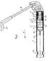
- the drive devices shown in the figures have a guide tube 7, in which one of a propellant driven piston 2 is guided.
- a propellant driven piston 2 For driving the piston 2 is inside the piston Gas generator 1 arranged.
- the gas generator 1 In the drive direction (arrow A) of the piston 2, the gas generator 1 is on front end of the piston 2.
- the gas generator 1 can be designed as described in EP-A 0 567 113 is described, i.e. the gas generator 1 has on it Blowing agent outlet side 3 a bursting floor 20. This The floor opens when the gas generator is ignited 1.
- the propellant can then in a piston interior 4 exit.
- This piston interior 4 is a combustion chamber educated. The combustion takes place in this combustion chamber of the exploding propellant.
- the gas generator can also be configured in two stages be as described in DE-A-42 28 696, i.e. the gas generator has explosives as the blowing agent with different explosion speeds, the first stage gas already mainly by one or more explosives the ignition device can be formed.
- the ignition can preferably with the help of an electrical ignition device 14 with power supply 22. It is natural mechanical ignition also possible.
- the piston interior 4 serving as the combustion chamber also serves to take up rope compression 17, which compared to the diameter of the traction 15 serving rope a widened Has diameter.
- the cable compression 17 has further a support ring 19 which on the inside on Piston plate 18 also bears firmly in the rest position (Fig. 1).
- the piston interior 4, which serves to accommodate the cable compression 17, also acts as a combustion chamber in which the Blowing agent outlet side 3 of the gas generator 1 directed is.
- the backstop 9 has a in Fig. 1 expandable locking element 10, which in the embodiment from several e.g. three ring segments consists. It can also be designed as a snap ring.
- This locking element 10 is on a conical Extension 11 out.
- the conical extension 11 is molded on the outside of the piston crown 18.
- the conical extension 11 is hollow. Be Interior stands over leakage openings 23 with the Pressure chamber 6 in connection, in which the outlet opening or outlet openings 5 are directed. In the rest position is the conical extension 11 on a closure element 8 of the guide tube 7 supported.
- This closure element can be used as a plastic plug be trained and a filter for combustion residues form.
- the other pipe end can also be used with one Closure element be equipped.
- the locking element 10 can with the help of a revolving Spring element 21 on the conical extension 11 be guided and against a circumferential rubber cushion 24 concerns.
- the locking element 10 is designed in such a way that it can be freely guided in the drive direction A along the Inner wall of the guide tube 7 can be guided. Contrary to the drive direction A, the locking element 10 expanded by the conical extension 11 and comes into motion-blocking engagement with the Inner wall of the guide tube. For this, the Sperring prefers a tapered engagement edge 13 have.
- To support the movement-inhibiting Engagement of the locking element 10 in the guide tube 7 can on the inner wall of the Guide tube formed additional circumferential grooves 12 be.
- the cross section of these circumferential grooves 12 is designed so that the tapered Engagement edge 13 on the locking element with positive and non-positive connection can intervene. Seen in direction of movement A. has the locking element, starting from the circumferential pointed edge 13 a beveled Circumferential surface. This will make the Locking element in the direction of movement A in the illustrated Embodiment achieved.
- the traction means 15 designed as a traction rope is through the closure element 8 to the component to be moved guided.
- the drive movement of the piston 2 is in the guide tube 7 at the tube end Narrowing 26 (Fig. 2) provided.
- this narrowing 26 runs the piston 2 with its front conical molded part 25, is braked and stopped.
- the tightened state is through the backstop 9, which with the inner wall of the Guide tube 7 in motion-blocking engagement comes, maintain.
- Acting on the traction means 15 Forces are generated by the rope compression supported on piston 2 17 recorded and on a short path over the piston crown and the backstop 9 in the Pipe 7 passed.
- the tube 7 is stationary, e.g. on one Vehicle body, supported.
- the backstop 9 which also as Reverse brake can act from rolling elements (balls) 27, which are in their normal position on a ring 28 elastic material.
- the rolling elements 27 are in a tapered annular piston extensive space. Has on the inside this room has a bevelled surface. This is formed by hard shells 29 which have a piston part 30 made of softer material, for example an aluminum alloy.
- the other ring-shaped Limitation is formed by the inner surface the guide tube 7.
- the traction means 15 designed as a traction rope is also included a partially illustrated belt buckle 31 one Seat belt connected in a motor vehicle. Due to the driven piston 2, the belt buckle for example by a distance of 80 mm retracted so that the seat belt on Body of the vehicle occupant is tightened.
Landscapes
- Engineering & Computer Science (AREA)
- Mechanical Engineering (AREA)
- Automotive Seat Belt Assembly (AREA)
- Vehicle Body Suspensions (AREA)
- Supply Devices, Intensifiers, Converters, And Telemotors (AREA)
- Lining Or Joining Of Plastics Or The Like (AREA)
- Reciprocating Pumps (AREA)
- Endoscopes (AREA)
- Sampling And Sample Adjustment (AREA)
- Surgical Instruments (AREA)
- Electrical Discharge Machining, Electrochemical Machining, And Combined Machining (AREA)
- Seal Device For Vehicle (AREA)
- Valve Device For Special Equipments (AREA)
Claims (15)
- Dispositif d'actionnement pour la tension d'une ceinture de sécurité de véhicule avec un tuyau de guidage (7), un piston (2) guidé dans le tuyau de guidage, gui peut être entraíné par un générateur de gaz (1) disposé dans le piston, des moyens de traction (15), lesquels relient le piston à une partie à entraíner, et un compartiment de pression formé dans le tuyau de guidage, dans lequel un gaz propulseur généré à l'intérieur du piston par le générateur de gaz sort par au moins un orifice de sortie dans le piston, le générateur de gaz (1) présentant un côté sortie d'agent propulseur dirigé dans un compartiment intérieur de piston qui est ouvert par l'agent propulseur allumé dans le générateur de gaz, et le compartiment intérieur de piston étant conçu comme un compartiment de comoustion pour les agents propulseurs sortant du générateur de gaz, caractérisé en ce que le tuyau de guidage (7) est appuyé de façon fixe, et en ce qu'il est prévu sur l'extrémité du piston, dans le sens d'entraínement, un dispositif de blocage de recul (9) qui peut être amené en prise, bloquant le mouvement du piston avec la paroi interne du tuyau de guidage (7), pour le blocage d'un déplacement de piston dans le sens contraire au sens d'entraínement.
- Dispositif selon la revendication 1, caractérisé en ce que le compartiment de pression (6) est fermé sur l'extrémité du tuyau de guidage (7) par un élément de fermeture (8) qui se présente sous la forme d'un filtre pour des résidus de combustion.
- Dispositif selon la revendication 1 ou 2, caractérisé en ce que le dispositif de blocage de recul (9) présente un élément de blocage (10), extensible radialement par rapport à l'axe du tuyau de guidage (7), qui est guidé sur une pièce ajoutée conique (11) du piston (2) de telle façon que l'élément de blocage (10) peut être guidé librement dans le sens d'entraínement sur la paroi interne du tuyau de guidage (7) et, dans le cas d'un mouvement de piston dirigé dans le sens contraire au sens d'entraínement, peut être élargi par la pièce ajoutée (11) conique pour un engrènement de blocage avec la paroi interne du tuyau de guidage (7).
- Dispositif selon la revendication 3, caractérisé en ce que la pièce ajoutée conique (11) a une conception creuse et présente en cet endroit au moins un orifice de sortie (5).
- Dispositif selon la revendication 3 ou 4, caractérisé en ce que la paroi interne du tuyau de guidage (7) présente des rainures (12) périphériques avec lesquelles l'élément de blocage (10) élargi peut être amené en prise.
- Dispositif selon l'une quelconque des revendications 3 à 5, caractérisé en ce que l'élément de blocage (10) présente un bord (13) pointu qui s'engage avec la paroi interne du tuyau de guidage (7) lors de l'élargissement de la bague.
- Dispositif selon l'une quelconque des revendications 3 à 6, caractérisé en ce que l'élément de blocage (10) est installé avec une précontrainte sur la pièce ajoutée conique (11).
- Dispositif selon l'une quelconque des revendications 1 à 7, caractérisé en ce que le générateur de gaz (1) est conçu de manière que le gaz propulseur sorte en au moins deux étapes, le gaz sortant pendant la première étape exerçant un effet d'entraínement réduit par rapport au gaz de la deuxième étape suivante ou aux étapes consécutives sur le piston (2).
- Dispositif selon l'une quelconque des revendications 1 à 8, caractérisé en ce que le générateur de gaz (1) présente un dispositif d'allumage (14) électrique.
- Dispositif selon l'une quelconque des revendications 1 à 9, caractérisé en ce que les moyens de traction (15) sont conçus comme un câble de traction et sont appuyés de façon fixe sur le piston (2) par l'intermédiaire d'un dispositif de compression de câble (17) qui présente un diamètre supérieur au câble de traction.
- Dispositif selon l'une quelconque des revendications 1 à 10, caractérisé en ce que le piston (7) est appuyé sur l'élément de fermeture (8) en service normal.
- Dispositif selon la revendication 10, caractérisé en ce que le au moins un orifice de sortie (5) est disposé dans une bague d'appui (19) grâce à un évidement formé sur le dispositif de compression de câble (17), laquelle bague est appuyée de façon fixe sur le fond de piston à l'intérieur du piston.
- Dispositif selon l'une quelconque des revendications 3 à 12, caractérisé en ce que la pièce ajoutée conique (11) est formée à l'extérieur sur le fond de piston (18).
- Dispositif selon l'une quelconque des revendications 1 à 13, caractérisé en ce que, sur l'extrémité du mouvement du piston (7), les moyens de traction (15) sont guidés sur le piston dans le sens d'entraínement, de façon ralentie et permettant de continuer de se déplacer.
- Dispositif selon la revendication 14, caractérisé en ce que, entre le piston (7) et le dispositif de compression de câble (17), il est prévu un frein (16) qui ralentit le déplacement ultérieur du dispositif de traction (15) par rapport au piston (7) arrêté.
Applications Claiming Priority (2)
| Application Number | Priority Date | Filing Date | Title |
|---|---|---|---|
| DE4332206A DE4332206C2 (de) | 1993-09-22 | 1993-09-22 | Antriebsvorrichtung |
| DE4332206 | 1993-09-22 |
Publications (4)
| Publication Number | Publication Date |
|---|---|
| EP0644089A2 EP0644089A2 (fr) | 1995-03-22 |
| EP0644089A3 EP0644089A3 (fr) | 1995-12-06 |
| EP0644089B1 EP0644089B1 (fr) | 1996-11-20 |
| EP0644089B2 true EP0644089B2 (fr) | 1999-08-04 |
Family
ID=6498312
Family Applications (1)
| Application Number | Title | Priority Date | Filing Date |
|---|---|---|---|
| EP94113246A Expired - Lifetime EP0644089B2 (fr) | 1993-09-22 | 1994-08-24 | Dispositif d'actionnement |
Country Status (5)
| Country | Link |
|---|---|
| US (1) | US5519997A (fr) |
| EP (1) | EP0644089B2 (fr) |
| AT (1) | ATE145369T1 (fr) |
| DE (2) | DE4332206C2 (fr) |
| ES (1) | ES2097591T5 (fr) |
Families Citing this family (37)
| Publication number | Priority date | Publication date | Assignee | Title |
|---|---|---|---|---|
| DE19529198A1 (de) * | 1995-08-09 | 1997-02-13 | Opel Adam Ag | Pyrotechnischer Gurtstraffer |
| RU2116902C1 (ru) * | 1995-08-15 | 1998-08-10 | Акционерное общество "НОРМА" | Устройство для упреждающего натяжения лямки ремня безопасности транспортного средства |
| US5671949A (en) * | 1995-12-20 | 1997-09-30 | Trw Vehicle Safety Systems Inc. | Seat belt pretensioner |
| DE29600777U1 (de) | 1996-01-17 | 1996-02-29 | HS Technik und Design Technische Entwicklungen GmbH, 82234 Weßling | Vorrichtung zum gleichzeitigen Straffen mehrerer in einem Kraftfahrzeug angeordneter Sicherheitsgurte |
| DE29605818U1 (de) * | 1996-03-28 | 1996-07-25 | Trw Occupant Restraint Systems Gmbh, 73551 Alfdorf | Fahrzeuginsassen-Rückhaltesystem mit einem Gurtstraffer |
| DE29609054U1 (de) * | 1996-05-20 | 1996-09-19 | Trw Occupant Restraint Systems Gmbh, 73551 Alfdorf | Gurtstraffer für ein Fahrzeuginsassen-Rückhaltesystem |
| DE29612781U1 (de) * | 1996-07-23 | 1996-11-21 | Trw Occupant Restraint Systems Gmbh, 73551 Alfdorf | Pyrotechnische Linearantriebseinrichtung für einen Gurtstraffer |
| GB9616639D0 (en) * | 1996-08-08 | 1996-09-25 | Alliedsignal Ltd | Pretensioner for vehicle safety restraint |
| DE69718114T2 (de) * | 1996-08-08 | 2003-09-25 | Breed Automotive Technology, Inc. | Gurtstrammer für ein Fahrzeuginsassen- Rückhaltesystem |
| DE29616414U1 (de) * | 1996-09-20 | 1997-01-23 | Trw Occupant Restraint Systems Gmbh, 73551 Alfdorf | Gurtstraffer |
| FR2758503B1 (fr) * | 1997-01-23 | 1999-03-26 | Faure Bertrand Equipements Sa | Siege de vehicule automobile incluant un pretensionneur pour ceinture de securite |
| DE29702125U1 (de) * | 1997-02-07 | 1997-06-05 | Trw Occupant Restraint Systems Gmbh, 73551 Alfdorf | Fahrzeuginsassen-Rückhaltesystem |
| DE19846227A1 (de) * | 1998-10-07 | 2000-04-13 | Breed Automotive Tech | Kolbenantrieb zum Straffen eines Kraftfahrzeugsicherheitsgurtes |
| DE29819095U1 (de) * | 1998-10-27 | 2000-04-27 | Dittrich, Klaus-Jürgen, 28832 Achim | Gurtstraffer |
| US6076856A (en) * | 1999-01-12 | 2000-06-20 | General Motors Corporation | Belt tension and energy absorbing apparatus |
| US6182525B1 (en) * | 1999-02-25 | 2001-02-06 | Trw Vehicle Safety Systems Inc. | Movable vehicle pedal apparatus |
| DE19927513C2 (de) * | 1999-06-16 | 2003-09-18 | Breed Automotive Tech | Vorrichtung zum Straffen eines Fahrzeugsicherheitsgurtes |
| DE19964258C2 (de) | 1999-06-16 | 2003-09-11 | Breed Automotive Tech | Vorrichtung zum Straffen eines Fahrzeugsicherheitsgurtes |
| DE19960848B4 (de) | 1999-12-16 | 2005-07-07 | Key Safety Systems, Inc., Sterling Heights | Vorrichtung zum Straffen eines Sicherheitsgurtes |
| DE10035117A1 (de) | 2000-07-19 | 2002-01-31 | Breed Automotive Tech | Ummantelter Kugelring sowie Verfahren zu seiner Herstellung |
| DE10105500B4 (de) | 2001-02-07 | 2004-02-05 | Breed Automotive Technology, Inc., Lakeland | Vorrichtung zum Straffen eines in einem Fahrzeugfond angeordneten Dreipunktsicherheitsgurtes |
| DE10112853A1 (de) | 2001-03-16 | 2002-10-02 | Breed Automotive Tech | Dreipunktsicherheitsgurtsystem für einen Kraftfahrzeugvordersitz |
| DE10126119C1 (de) * | 2001-05-29 | 2002-11-07 | Breed Automotive Tech | Vorrichtung zum seitlichen Herausführen eines in einem Rohr verlegten elektrischen Kabels |
| DE20111638U1 (de) * | 2001-07-12 | 2001-09-27 | Breed Automotive Technology, Inc., Lakeland, Fla. | Linearstrafferantrieb zum Straffen eines Fahrzeugsicherheitsgurtes |
| DE20209284U1 (de) * | 2002-06-14 | 2003-10-16 | Breed Automotive Technology, Inc., Lakeland, Fla. | Vorrichtung zum Straffen eines Sicherheitsgurtes |
| DE10303377A1 (de) * | 2003-01-29 | 2004-08-05 | Dynamit Nobel Ais Gmbh Automotive Ignition Systems | Pyromechanisches Trennelement |
| DE10325473A1 (de) * | 2003-06-05 | 2005-01-05 | Keiper Gmbh & Co. Kg | Gurtschloßvorrichtung für einen Fahrzeugsitz |
| DE102005008108B4 (de) * | 2004-02-24 | 2007-08-09 | Delphi Technologies, Inc., Troy | Gurtstraffersystem für Kraftfahrzeuge |
| US7380832B2 (en) * | 2005-04-05 | 2008-06-03 | Takata Seat Belts, Inc. | Pretensioner with integrated gas generator |
| US7533902B2 (en) * | 2006-05-31 | 2009-05-19 | Key Safety Systems, Inc. | Seat belt pretensioner using preformed tubes |
| JP5294444B2 (ja) * | 2007-10-02 | 2013-09-18 | テイ・エス テック株式会社 | 車両用シート |
| EP2247473A4 (fr) * | 2008-03-07 | 2013-03-06 | Autoliv Dev | Dispositif pré-tendeur |
| US8585090B2 (en) | 2010-06-29 | 2013-11-19 | Autoliv Asp, Inc. | High efficiency pretensioner |
| US8226122B2 (en) | 2010-11-12 | 2012-07-24 | Autoliv Asp, Inc. | Thin linear seatbelt pretensioner |
| US8528987B2 (en) | 2012-01-30 | 2013-09-10 | Autoliv Asp, Inc. | Linear seat belt pretensioner |
| DE102020200264B4 (de) * | 2020-01-10 | 2022-06-23 | Joyson Safety Systems Germany Gmbh | Strafferantrieb für eine Sicherheitsgurteinrichtung und Anordnung mit Strafferantrieb |
| US11904796B2 (en) * | 2020-02-14 | 2024-02-20 | Joyson Safety Systems Acquisition Llc | Seat belt pretensioner system |
Citations (5)
| Publication number | Priority date | Publication date | Assignee | Title |
|---|---|---|---|---|
| FR2491340A1 (fr) † | 1980-10-06 | 1982-04-09 | Repa Feinstanzwerk Gmbh | Tendeur de rappel pour un enrouleur automatique de ceinture de securite |
| EP0093237A1 (fr) † | 1982-04-29 | 1983-11-09 | Bayern-Chemie Gesellschaft für flugchemische Antriebe mit beschränkter Haftung | Dispositif de rétraction pour ceintures de sécurité de véhicules |
| EP0560181A1 (fr) † | 1992-03-13 | 1993-09-15 | HS Technik und Design Technische Entwicklungen GmbH | Appareil de propulsion pour mettre en mouvement des pièces de véhicules d'une position normale à une position de sécurité |
| EP0567113A1 (fr) † | 1992-04-22 | 1993-10-27 | HS Technik und Design Technische Entwicklungen GmbH | Dispositf générateur de gaz |
| EP0600689A1 (fr) † | 1992-12-02 | 1994-06-08 | Alliedsignal Limited | Rétracteur de ceinture de sécurité à prétensionneur |
Family Cites Families (15)
| Publication number | Priority date | Publication date | Assignee | Title |
|---|---|---|---|---|
| US3024592A (en) * | 1960-11-09 | 1962-03-13 | Lockheed Aircraft Corp | Pin actuating device |
| DE2249786A1 (de) * | 1972-10-11 | 1974-04-25 | Bayern Chemie Gmbh Flugchemie | Sicherheitseinrichtung fuer die insassen von fahrzeugen, insbesondere von kraftfahrzeugen |
| DE2253657C2 (de) * | 1972-11-02 | 1984-09-06 | Dynamit Nobel Ag, 5210 Troisdorf | Vorrichtung zum Spannen von Sicherheitsgurten in Fahrzeugen |
| JPS49125430U (fr) * | 1973-02-26 | 1974-10-26 | ||
| SE380588B (sv) * | 1973-12-21 | 1975-11-10 | Foerenade Fabriksverken | Arbetscylinder med i valfritt lege lasbar kolv |
| DE2505624A1 (de) * | 1975-02-11 | 1976-08-19 | Volkswagenwerk Ag | Spannvorrichtung fuer einen sicherheitsgurt von fahrzeugen, insbesondere kraftfahrzeugen |
| DE2540952C2 (de) * | 1975-09-13 | 1984-08-16 | Volkswagenwerk Ag, 3180 Wolfsburg | Gurtspannvorrichtung für einen Sicherheitsgurt |
| US4054032A (en) * | 1976-09-03 | 1977-10-18 | Networks Electronic Corporation | Explosive actuated pin puller |
| US4385775A (en) * | 1978-03-21 | 1983-05-31 | Nippon Soken, Inc. | Seat belt tensioning device for vehicle |
| JPS5845717Y2 (ja) * | 1978-06-07 | 1983-10-18 | 株式会社日本自動車部品総合研究所 | シ−トベルト引締め装置の逆戻り防止装置 |
| FR2460407A1 (fr) * | 1979-06-29 | 1981-01-23 | Angeviniere Sa | Dispositif de traction a course irreversible |
| DE8816557U1 (de) * | 1988-03-22 | 1989-11-16 | Autoflug GmbH & Co Fahrzeugtechnik, 2084 Rellingen | Antriebsvorrichtung für Gurtstrammer |
| US4860698A (en) * | 1988-05-11 | 1989-08-29 | Networks Electronic Corp. | Pyrotechnic piston device |
| GB2221747B (en) * | 1988-08-09 | 1993-02-17 | Graviner Ltd Kidde | Apparatus and methods for producing motive power |
| DE4228696C2 (de) * | 1992-08-28 | 1996-06-20 | Hs Tech & Design | Pyrotechnischer Gasgenerator |
-
1993
- 1993-09-22 DE DE4332206A patent/DE4332206C2/de not_active Expired - Lifetime
-
1994
- 1994-08-24 ES ES94113246T patent/ES2097591T5/es not_active Expired - Lifetime
- 1994-08-24 DE DE59401075T patent/DE59401075D1/de not_active Expired - Lifetime
- 1994-08-24 AT AT94113246T patent/ATE145369T1/de not_active IP Right Cessation
- 1994-08-24 EP EP94113246A patent/EP0644089B2/fr not_active Expired - Lifetime
- 1994-09-22 US US08/310,445 patent/US5519997A/en not_active Expired - Lifetime
Patent Citations (5)
| Publication number | Priority date | Publication date | Assignee | Title |
|---|---|---|---|---|
| FR2491340A1 (fr) † | 1980-10-06 | 1982-04-09 | Repa Feinstanzwerk Gmbh | Tendeur de rappel pour un enrouleur automatique de ceinture de securite |
| EP0093237A1 (fr) † | 1982-04-29 | 1983-11-09 | Bayern-Chemie Gesellschaft für flugchemische Antriebe mit beschränkter Haftung | Dispositif de rétraction pour ceintures de sécurité de véhicules |
| EP0560181A1 (fr) † | 1992-03-13 | 1993-09-15 | HS Technik und Design Technische Entwicklungen GmbH | Appareil de propulsion pour mettre en mouvement des pièces de véhicules d'une position normale à une position de sécurité |
| EP0567113A1 (fr) † | 1992-04-22 | 1993-10-27 | HS Technik und Design Technische Entwicklungen GmbH | Dispositf générateur de gaz |
| EP0600689A1 (fr) † | 1992-12-02 | 1994-06-08 | Alliedsignal Limited | Rétracteur de ceinture de sécurité à prétensionneur |
Also Published As
| Publication number | Publication date |
|---|---|
| DE4332206C2 (de) | 1997-08-14 |
| DE59401075D1 (de) | 1997-01-02 |
| ATE145369T1 (de) | 1996-12-15 |
| ES2097591T5 (es) | 1999-10-01 |
| EP0644089A2 (fr) | 1995-03-22 |
| ES2097591T3 (es) | 1997-04-01 |
| DE4332206A1 (de) | 1995-03-23 |
| US5519997A (en) | 1996-05-28 |
| EP0644089A3 (fr) | 1995-12-06 |
| EP0644089B1 (fr) | 1996-11-20 |
Similar Documents
| Publication | Publication Date | Title |
|---|---|---|
| EP0644089B2 (fr) | Dispositif d'actionnement | |
| EP0539872B1 (fr) | Générateur de gaz, en particulier pour un coussin gonflable de protection d'un passager de véhicule contre les blessures | |
| DE2436754C3 (de) | Spannvorrichtung für Sicherheitsgurte | |
| EP0680857B1 (fr) | Générateur de gaz pour système de retenue dans un véhicule | |
| EP0616928B1 (fr) | Tendeur de sangle pour ceintures de sécurité avec moteur pyrotechnique | |
| EP0629531A1 (fr) | Dispositif d'entraînement pyrotechnique en rotation d'une bobine d'enrouleur automatique de ceinture de sécurité | |
| EP1232916A1 (fr) | Prétensionneur de ceinture de sécurité | |
| DE19927270C2 (de) | Rückhaltevorrichtung für einen auf eine Gurtspule aufwickelbaren Sicherheitsgurt eines Kraftfahrzeugs | |
| DE602004007190T2 (de) | Modulierbarer Dämpfer mit pyrotechnischen Gasen | |
| DE2330635A1 (de) | Neue, durch schiesstoff getriebene einstellvorrichtung, insbesondere zum spannen von sicherheitsgurten | |
| EP0529501B1 (fr) | Dispositif de tendeur de rappel pour tendre une ceinture de sécurité d'un véhicule automobile | |
| EP0552668B1 (fr) | Tendeur de ceinture avec moteur pyrotechnique à piston-cylindre | |
| EP0944504B1 (fr) | Generateur de gaz hybride pour un airbag | |
| DE10010379A1 (de) | Sicherheitsgurtsystem | |
| DE19900646A1 (de) | Betätigungsvorrichtung und -verfahren für Sicherheitseinrichtungen in einem Fahrzeug | |
| DE102009030215B4 (de) | Sicherheitsgurteinrichtung mit einem Gurtstraffer und einer Kraftbegrenzungseinrichtung | |
| EP0560181B1 (fr) | Appareil de propulsion pour mettre en mouvement des pièces de véhicules d'une position normale à une position de sécurité | |
| DE69702438T2 (de) | Vorspannungsvorrichtung für sicherheitsgurte | |
| DE4213265C2 (de) | Treibgasgeneratoranordnung | |
| DE19641224B4 (de) | Antriebsvorrichtung, insbesondere zum Straffen eines Sicherheitsgurtes in einem Kraftfahrzeug | |
| DE19844488A1 (de) | Pyrotechnischer Antrieb,insbesondere für Fahrzeuginsassen-Rückhaltesysteme | |
| DE2946717A1 (de) | Vorrichtung zum spannen eines gurts | |
| DE19957794C2 (de) | Sicherheitsgurtanordnung bei Fahrzeugen | |
| DE2411702A1 (de) | Kraftbegrenzer, der aus einem zylinder und einem kolben besteht | |
| EP0970858A2 (fr) | Prétensionneur de ceinture de sécurité |
Legal Events
| Date | Code | Title | Description |
|---|---|---|---|
| PUAI | Public reference made under article 153(3) epc to a published international application that has entered the european phase |
Free format text: ORIGINAL CODE: 0009012 |
|
| AK | Designated contracting states |
Kind code of ref document: A2 Designated state(s): AT DE ES FR GB IT NL SE |
|
| PUAL | Search report despatched |
Free format text: ORIGINAL CODE: 0009013 |
|
| AK | Designated contracting states |
Kind code of ref document: A3 Designated state(s): AT DE ES FR GB IT NL SE |
|
| 17P | Request for examination filed |
Effective date: 19960125 |
|
| GRAG | Despatch of communication of intention to grant |
Free format text: ORIGINAL CODE: EPIDOS AGRA |
|
| 17Q | First examination report despatched |
Effective date: 19960227 |
|
| GRAH | Despatch of communication of intention to grant a patent |
Free format text: ORIGINAL CODE: EPIDOS IGRA |
|
| GRAH | Despatch of communication of intention to grant a patent |
Free format text: ORIGINAL CODE: EPIDOS IGRA |
|
| GRAA | (expected) grant |
Free format text: ORIGINAL CODE: 0009210 |
|
| AK | Designated contracting states |
Kind code of ref document: B1 Designated state(s): AT DE ES FR GB IT NL SE |
|
| PG25 | Lapsed in a contracting state [announced via postgrant information from national office to epo] |
Ref country code: NL Free format text: LAPSE BECAUSE OF FAILURE TO SUBMIT A TRANSLATION OF THE DESCRIPTION OR TO PAY THE FEE WITHIN THE PRESCRIBED TIME-LIMIT Effective date: 19961120 |
|
| REF | Corresponds to: |
Ref document number: 145369 Country of ref document: AT Date of ref document: 19961215 Kind code of ref document: T |
|
| ITF | It: translation for a ep patent filed | ||
| ET | Fr: translation filed | ||
| REF | Corresponds to: |
Ref document number: 59401075 Country of ref document: DE Date of ref document: 19970102 |
|
| GBT | Gb: translation of ep patent filed (gb section 77(6)(a)/1977) |
Effective date: 19970124 |
|
| REG | Reference to a national code |
Ref country code: ES Ref legal event code: FG2A Ref document number: 2097591 Country of ref document: ES Kind code of ref document: T3 |
|
| PLBQ | Unpublished change to opponent data |
Free format text: ORIGINAL CODE: EPIDOS OPPO |
|
| PLBI | Opposition filed |
Free format text: ORIGINAL CODE: 0009260 |
|
| PLBF | Reply of patent proprietor to notice(s) of opposition |
Free format text: ORIGINAL CODE: EPIDOS OBSO |
|
| 26 | Opposition filed |
Opponent name: ALLIEDSIGNAL LIMITED Effective date: 19970820 |
|
| NLR1 | Nl: opposition has been filed with the epo |
Opponent name: ALLIEDSIGNAL LIMITED |
|
| PLBF | Reply of patent proprietor to notice(s) of opposition |
Free format text: ORIGINAL CODE: EPIDOS OBSO |
|
| PLAC | Information related to filing of opposition modified |
Free format text: ORIGINAL CODE: 0008299OPPO |
|
| PGFP | Annual fee paid to national office [announced via postgrant information from national office to epo] |
Ref country code: AT Payment date: 19980831 Year of fee payment: 5 Ref country code: NL Payment date: 19980831 Year of fee payment: 5 |
|
| PLAW | Interlocutory decision in opposition |
Free format text: ORIGINAL CODE: EPIDOS IDOP |
|
| PLAW | Interlocutory decision in opposition |
Free format text: ORIGINAL CODE: EPIDOS IDOP |
|
| PUAH | Patent maintained in amended form |
Free format text: ORIGINAL CODE: 0009272 |
|
| STAA | Information on the status of an ep patent application or granted ep patent |
Free format text: STATUS: PATENT MAINTAINED AS AMENDED |
|
| 27A | Patent maintained in amended form |
Effective date: 19990804 |
|
| AK | Designated contracting states |
Kind code of ref document: B2 Designated state(s): AT DE ES FR GB IT NL SE |
|
| PG25 | Lapsed in a contracting state [announced via postgrant information from national office to epo] |
Ref country code: AT Free format text: LAPSE BECAUSE OF NON-PAYMENT OF DUE FEES Effective date: 19990824 |
|
| REG | Reference to a national code |
Ref country code: ES Ref legal event code: DC2A Kind code of ref document: T5 Effective date: 19990817 |
|
| GBTA | Gb: translation of amended ep patent filed (gb section 77(6)(b)/1977) | ||
| ET3 | Fr: translation filed ** decision concerning opposition | ||
| NLV1 | Nl: lapsed or annulled due to failure to fulfill the requirements of art. 29p and 29m of the patents act | ||
| PGFP | Annual fee paid to national office [announced via postgrant information from national office to epo] |
Ref country code: ES Payment date: 20000816 Year of fee payment: 7 |
|
| PGFP | Annual fee paid to national office [announced via postgrant information from national office to epo] |
Ref country code: GB Payment date: 20010629 Year of fee payment: 8 |
|
| PGFP | Annual fee paid to national office [announced via postgrant information from national office to epo] |
Ref country code: SE Payment date: 20010803 Year of fee payment: 8 |
|
| REG | Reference to a national code |
Ref country code: GB Ref legal event code: IF02 |
|
| PG25 | Lapsed in a contracting state [announced via postgrant information from national office to epo] |
Ref country code: GB Free format text: LAPSE BECAUSE OF NON-PAYMENT OF DUE FEES Effective date: 20020824 |
|
| PG25 | Lapsed in a contracting state [announced via postgrant information from national office to epo] |
Ref country code: SE Free format text: LAPSE BECAUSE OF NON-PAYMENT OF DUE FEES Effective date: 20020825 |
|
| PG25 | Lapsed in a contracting state [announced via postgrant information from national office to epo] |
Ref country code: ES Free format text: LAPSE BECAUSE OF NON-PAYMENT OF DUE FEES Effective date: 20020826 |
|
| EUG | Se: european patent has lapsed | ||
| GBPC | Gb: european patent ceased through non-payment of renewal fee |
Effective date: 20020824 |
|
| PGFP | Annual fee paid to national office [announced via postgrant information from national office to epo] |
Ref country code: FR Payment date: 20030804 Year of fee payment: 10 |
|
| REG | Reference to a national code |
Ref country code: ES Ref legal event code: FD2A Effective date: 20030912 |
|
| PG25 | Lapsed in a contracting state [announced via postgrant information from national office to epo] |
Ref country code: FR Free format text: LAPSE BECAUSE OF NON-PAYMENT OF DUE FEES Effective date: 20050429 |
|
| REG | Reference to a national code |
Ref country code: FR Ref legal event code: ST |
|
| PLAB | Opposition data, opponent's data or that of the opponent's representative modified |
Free format text: ORIGINAL CODE: 0009299OPPO |
|
| PGFP | Annual fee paid to national office [announced via postgrant information from national office to epo] |
Ref country code: DE Payment date: 20130902 Year of fee payment: 20 |
|
| PGFP | Annual fee paid to national office [announced via postgrant information from national office to epo] |
Ref country code: IT Payment date: 20140127 Year of fee payment: 20 |
|
| REG | Reference to a national code |
Ref country code: DE Ref legal event code: R071 Ref document number: 59401075 Country of ref document: DE |
|
| PG25 | Lapsed in a contracting state [announced via postgrant information from national office to epo] |
Ref country code: DE Free format text: LAPSE BECAUSE OF EXPIRATION OF PROTECTION Effective date: 20140826 |