EP0644321B1 - Levier d'accélérateur de sécurité - Google Patents
Levier d'accélérateur de sécurité Download PDFInfo
- Publication number
- EP0644321B1 EP0644321B1 EP94114678A EP94114678A EP0644321B1 EP 0644321 B1 EP0644321 B1 EP 0644321B1 EP 94114678 A EP94114678 A EP 94114678A EP 94114678 A EP94114678 A EP 94114678A EP 0644321 B1 EP0644321 B1 EP 0644321B1
- Authority
- EP
- European Patent Office
- Prior art keywords
- throttle
- lever
- lever means
- throttle control
- shaft
- Prior art date
- Legal status (The legal status is an assumption and is not a legal conclusion. Google has not performed a legal analysis and makes no representation as to the accuracy of the status listed.)
- Expired - Lifetime
Links
- 239000000446 fuel Substances 0.000 claims description 32
- 238000002485 combustion reaction Methods 0.000 claims description 9
- 230000004044 response Effects 0.000 claims description 4
- 125000006850 spacer group Chemical group 0.000 claims description 2
- 230000007246 mechanism Effects 0.000 description 4
- 238000003466 welding Methods 0.000 description 3
- 229910000831 Steel Inorganic materials 0.000 description 2
- 239000010959 steel Substances 0.000 description 2
- 230000009471 action Effects 0.000 description 1
- 230000000712 assembly Effects 0.000 description 1
- 238000000429 assembly Methods 0.000 description 1
- 230000000994 depressogenic effect Effects 0.000 description 1
- 238000002347 injection Methods 0.000 description 1
- 239000007924 injection Substances 0.000 description 1
- 230000007257 malfunction Effects 0.000 description 1
- 230000009467 reduction Effects 0.000 description 1
Images
Classifications
-
- F—MECHANICAL ENGINEERING; LIGHTING; HEATING; WEAPONS; BLASTING
- F02—COMBUSTION ENGINES; HOT-GAS OR COMBUSTION-PRODUCT ENGINE PLANTS
- F02D—CONTROLLING COMBUSTION ENGINES
- F02D11/00—Arrangements for, or adaptations to, non-automatic engine control initiation means, e.g. operator initiated
- F02D11/04—Arrangements for, or adaptations to, non-automatic engine control initiation means, e.g. operator initiated characterised by mechanical control linkages
Definitions
- the present invention relates generally to throttle levers for internal combustion engines and specifically to a breakover throttle lever which avoids damage to the fuel pump and associated structures when excessive force is applied to the throttle lever.
- the present invention relates to a throttle lever assembly according to the preamble of claim 1.
- Throttle operating devices have long been employed in automotive and other vehicular internal combustion engines. These operating devices typically include a throttle lever attached to a throttle shaft and operatively connected to an associated throttle control linkage.
- the throttle control linkage is operatively connected to a foot-operated throttle pedal or "accelerator” or to another type of operator-actuated throttle control element within the vehicle's passenger compartment. This permits the operator to control the action of a fuel supply system, such as a fuel injection system or throttle valve, through the throttle control linkage and associated throttle lever simply by pressing down or releasing the throttle pedal or by moving the throttle control element.
- Throttle levers are normally arranged to move between two positions: an idle position wherein sufficient fuel is supplied to the engine so that it will run at a predetermined idling speed, and a full throttle position wherein a maximum amount of fuel is supplied to the engine.
- the idle and full throttle positions are normally defined by adjustable stops.
- a return spring is typically used to bias the throttle lever to the setting required to maintain a preset engine idle speed when pressure on the throttle pedal is released or when the throttle control is fully retracted.
- Two part throttle levers one part of which is pivotally mounted with respect to the other to form a lever link, are normally used to provide the breakover function.
- the lever link is able to move or "break over" independently of the throttle lever when conditions require breakover capability.
- a torsion spring is typically provided on the throttle lever to urge the lever link toward its normal position and to return the lever link to its normal position upon release of the breakover causing force.
- High pressure fuel pump throttle shafts and components are particularly susceptible to damage if a throttle lever is not capable of independent movements in response to a breakover-causing force.
- a throttle return system including a two part lever and a coiled safety spring, which returns a throttle valve to the desired idle setting in the event of a failure of either the throttle return spring or the associated throttle control linkage.
- the central pivot connection of the two levers in this system allows a long travel distance between the idle and full throttle positions. Consequently, this system does not function as efficiently as might be desired, and the distance the throttle linkage elements are required to travel, particularly in the event of a malfunction, could damage the fuel pump internal components.
- One known throttle lever design includes a one way breakover mechanism to permit over travel of the throttle linkage when the throttle shaft reaches its full throttle position.
- This known design includes a torsion spring for biasing a link lever toward its normal operating position and for transmitting the spring biasing force to the link lever.
- a stop pin, mounted on the link lever, is arranged to be engaged by one end of the torsion spring and to form a stop to define the normal operating position of the link lever relative to the throttle lever.
- This throttle lever design has some limitations, however. It can be installed by the end user in a way that may overstress the throttle lever torsion spring and cause it to break. As in the design disclosed in the Marsh patent, the throttle lever and link lever are pivotally connected by a centrally located pivotal connector, which produces a long travel stroke.
- the throttle assemblies of the prior art typically provide a relatively large amount of "play" in the travel of the throttle lever and associated assembly components.
- the accelerator pedal or throttle control must be several inches from the floor of the vehicle, and connecting linkage structures are somewhat long and cumbersome. Reduction of the travel distance of the throttle lever and associated structures would provide a more compact and more efficient fuel throttling assembly.
- the prior art therefore, has failed to provide an efficient short stroke breakover throttle lever assembly for use with an internal combustion engine high pressure fuel pump that is capable of allowing overtravel of the throttle rod or linkage without damage to the fuel pump throttle lever or internal pump components.
- Object of the present invention is to overcome the disadvantages of the prior art and to provide a compact breakover throttle lever assembly for an internal combustion engine with a high pressure fuel pump, which requires only a short travel stroke but which allows overtravel of the throttle rod or linkage without damage to the fuel pump throttle lever or internal pump components.
- a breakover throttle lever assembly for a high pressure fuel pump of an internal combustion engine
- the breakover throttle lever assembly includes two lever elements pivotally connected to a point farthest from the fuel pump throttle shaft and held in coaxial alignment by a spring member.
- a throttle rod connection positioned centrally between the pivotal lever connection and the fuel pump connection connects one of the lever elements to the engine throttle pedal so that only a short travel distance between the idle and full throttle positions is required.
- the connected lever element pivots to a breakover position only if a predetermined force is applied to the throttle rod connection point which overcomes the force of the spring member.
- the breakover throttle lever assembly of the present invention is intended to be operably connected to the throttle shaft of a high pressure fuel pump in an internal combustion engine to rotate the throttle shaft between full throttle and idle positions in response to forces exerted on the throttle lever by an engine throttle control, such as an accelerator pedal, and a throttle return spring.
- an engine throttle control such as an accelerator pedal
- a throttle return spring Unless precautions are taken, a situation could arise in which continued application of force to the throttle control by a human operator could damage the throttle lever assembly and allow the throttle shaft to assume a full throttle position.
- Internal combustion engine designers have tried to avoid this problem by providing a breakover mechanism which prevents the throttle lever from remaining in the full throttle position in the event of damage to the throttle control or linkage mechanism without permitting excessive force to be applied to the fuel pump throttle lever.
- the breakover throttle lever assembly of the present invention effectively allows overtravel of the throttle rod or linkage without damage to the throttle lever or internal components of a high pressure fuel pump.
- the present breakover throttle lever provides both a short lever stroke and break
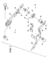
- Figure 1 illustrates, in exploded perspective view, the unassembled components of the breakover throttle lever assembly 10 of the present invention.
- the breakover throttle lever assembly 10 is attached to the throttle shaft (not shown) of a fuel pump (not shown) at a splined hole 12 and is secured to the throttle shaft by a bolt 14 and a nut 16.
- a throttle rod linkage (not shown) from the vehicle throttle pedal or throttle control (not shown) is attached to the assembly 10 at a ball joint 18.
- the assembly includes two main lever elements 20 and 22.
- the main lever elements are pivotally by a pivotal connection 25, which includes a shaft 24, that is secured, preferably by welding, to lever element 22, and a bushing 26.
- the bushing 26 is attached, preferably by welding, to throttle control lever element 20.
- the two main lever elements are then secured together by a clip 28 which fits into a groove 30 in shaft 24.
- Main lever element or throttle lever element 22 which will usually be positioned upwardly of lever element 24, includes a projecting tab 32, which may be integrally formed with the lever element or a separate structure secured to the lever element by welding or the like.
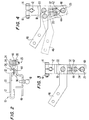
- a second projecting tab 34 is formed on a spacer link 36. This second projecting tab 34 extends in a direction opposite that of projecting tab 32 and is keyed to project through an aperture 38 in the main lever element 22 when the breakover throttle lever assembly is assembled as shown in Figures 2, 3 and 4.
- the dimensions of the aperture 38 limit the movement of the tab 34 and, therefore, the movement of the throttle control lever element 20.
- a torsion spring 40 is positioned about the bushing 26 and shaft 24 pivotal connection 25 between the main lever elements 20 and 22.
- the torsion spring 40 is formed with substantially straight legs 42 and 44, which contact the projecting tabs 32 and 34 when the components of the breakover throttle lever assembly are operably assembled to hold the main lever elements 20 and 22 in coaxial alignment.
- the components of the throttle lever assembly 10 are preferably formed of steel which has been cold rolled and carburized. Steel with the designations 1010, 1018 and the like are particularly suitable for the present breakover throttle lever assembly.
- the two main lever elements 20 and 22 are held in place against pivotal movement about the pivotal connection 25 by the force of the legs 42 and 44 of the torsion spring 40 on the projecting tabs 32 and 34. These lever elements move synchronously about the fuel pump throttle shaft (not shown) and are prevented from pivoting about the pivotal connection 25 unless a force in excess of a predetermined force, which is the force of the torsion spring 40, is applied to the throttle lever assembly. Such force typically is applied to the ball joint 18, which is connected through appropriate linkages (not shown) to the operator-actuated throttle pedal or throttle control. In the event one of the legs 42 or 44 broke or became separated from the tabs 32 and 34, the movement of throttle control lever 20 relative to throttle lever 22 would be limited by the lateral movement of tab 34 in aperture 38.
- the legs 42 and 44 of torsion spring 40 operate in a scissors manner to hold the tabs 32 and 34 and, thus, the main lever elements 20 and 22, in alignment until a force exceeding the predetermined force has been applied to the ball joint 18.
- the throttle control lever 20 pivots about the pivotal connection 25 while the throttle lever 22 does not. This prevents the movement of the fuel pump throttle shaft to an undesired full throttle position.
- Throttle control lever 20 is formed with a winged extension 46, which is positioned substantially coplanar to the ball joint 18 and is connected to a redundant return spring (not shown) that returns the throttle control lever to the position shown in Figure 3 when the force on the throttle control lever 20 is equal to or less than the force of the spring 40. This arrangement allows overtravel of the throttle rod or linkage attached at ball joint 18 without damaging the fuel pump throttle shaft or the fuel pump internal components.
- FIG. 4 illustrates the throttle lever assembly of the present invention in a breakover position, which is shown in dashed lines.
- the main lever elements 20 and 22 of the present invention are pivotally connected at a point, connection 25, that is as far from the fuel pump throttle shaft as possible.
- the throttle control linkage connection is then provided at ball joint 18, which is centrally positioned between the pivotal connection 25 and the fuel pump throttle shaft.
- the throttle lever assembly has a short travel distance from idle to full throttle, the assembly and its associated linkages are more compact.
- the long connecting rods required by the prior art are not needed. Instead, significantly shorter connecting rods can be used to produce a short stroke with breakover capability.
- the winged extension 46 which is attached to a redundant return spring (not shown), also requires shorter connections than those previously required so that this arrangement functions more efficiently.
- the fuel pedal, accelerator or other throttle control must move only a short distance between idle and full throttle.
- the breakover throttle lever assembly of the present invention will find its primary use as a component of an internal combustion engine throttle control system to assure optimum throttling function while avoiding damage to the fuel pump throttle shaft and components in the event excess force is applied to the throttle assembly control or linkage structures.
Landscapes
- Engineering & Computer Science (AREA)
- Chemical & Material Sciences (AREA)
- Combustion & Propulsion (AREA)
- Mechanical Engineering (AREA)
- General Engineering & Computer Science (AREA)
- Control Of Throttle Valves Provided In The Intake System Or In The Exhaust System (AREA)
- Auxiliary Drives, Propulsion Controls, And Safety Devices (AREA)
Claims (10)
- Assemblage de manette des gaz pour le fonctionnement d'un axe du papillon des gaz conçu pour régler l'écoulement de carburant en direction d'un moteur à combustion interne lorsque l'axe du papillon des gaz se déplace entre une position de marche à vide et une position à pleins gaz en réponse à un moyen de manette de commande des gaz (20), comprenant:caractérisé en ce quea) un moyen de manette des gaz (22) conçu pour être relié à l'axe du papillon des gaz pour déplacer l'axe du papillon des gaz entre la position de marche à vide et la position à pleins gaz en réponse au mouvement du moyen de manette de commande du papillon des gaz (20);b) un moyen de tringle du papillon des gaz raccordé au moyen de manette des gaz (22) et au moyen de manette de commande du papillon des gaz (20) pour limiter le degré de force qui peut être appliqué sur le moyen de manette des gaz (22) lorsque l'axe du papillon des gaz atteint au moins une position parmi soit la position de marche à vide et la position à pleins gaz;c) un moyen de raccord pivotant (25) situé à une extrémité du moyen de manette des gaz (22) en position distale par rapport à l'axe du papillon des gaz pour raccorder en pivotement le moyen de manette des gaz (22) et le moyen de manette de commande du papillon des gaz (20);d) le moyen de manette de commande du papillon des gaz (20) s'étend depuis le moyen de raccord pivotant (25) en direction de l'axe du papillon des gaz, essentiellement en alignement avec le moyen de manette des gaz (22); ete) un moyen de raccord de commande des gaz (18) est situé sur le moyen de manette de commande du papillon des gaz (20) essentiellement en position centrale entre le moyen de raccord pivotant (25) et l'axe du papillon des gaz pour venir se mettre en contact avec un élément de tringlerie pour le moyen de manette de commande du papillon des gaz (20).
- Assemblage de manette des gaz selon la revendication 1, caractérisé en ce que le moyen de raccord pivotant (25) englobe un moyen mis en état de précontrainte par ressort pour mettre ledit moyen de manette des gaz (22) et ledit moyen de manette de commande du papillon des gaz (20) en état de précontrainte dans une position de marche normale, dans lequel ledit moyen de manette des gaz (22) et ledit moyen de manette de commande du papillon des gaz (20) sont disposés en alignement axial et tournent de manière synchrone avec ledit axe du papillon des gaz.
- Assemblage de manette des gaz selon la revendication 2, caractérisé en ce que ledit moyen de manette des gaz (22) englobe une première portion de mise en contact par ressort et ledit moyen de manette de commande du papillon des gaz (20) englobe une seconde portion de mise en contact par ressort, ledit moyen de mise en état de précontrainte par ressort englobant un ressort (40) possédant une paire de branches (42, 44), dans lequel une desdites branches (42, 44) vient se mettre en contact avec ladite première portion de mise en contact par ressort et l'autre branche (42, 44) vient se mettre en contact avec ladite seconde portion de mise en contact par ressort.
- Assemblage de manette des gaz selon la revendication 3, caractérisé en ce que ledit moyen de manette des gaz (22) englobe un moyen d'orifice (38) pour que vienne s'y loger ladite seconde portion de mise en contact par ressort, dans lequel ledit moyen d'orifice (38) est dimensionné par rapport à ladite seconde portion de mise en contact par ressort de façon à limiter le mouvement latéral de cette dernière dans le cas où ladite branche (42, 44) dudit ressort (40) est empêchée de venir se mettre en contact avec ladite seconde portion de mise en contact par ressort.
- Assemblage de manette des gaz selon la revendication 4, caractérisé en ce que ladite seconde portion de mise en contact par ressort est réalisée sur un élément de tringle du papillon des gaz configuré pour épouser la configuration dudit moyen de manette de commande du papillon des gaz (20) et fixé audit moyen de manette de commande du papillon des gaz (20) de telle sorte que ladite seconde portion de mise en contact par ressort vient se caler dans ledit moyen d'orifice (38) lorsque ladite manette des gaz (10) est montée.
- Assemblage de manette des gaz selon l'une quelconque des revendications 2 à 5, caractérisé en ce que ledit moyen de manette de commande du papillon des gaz (20) est rotatif depuis ladite position de fonctionnement normale jusqu'à une position de retournement lorsque la force s'exerçant sur ledit moyen de raccord de commande des gaz (18) dépasse la force exercée par ledit moyen de mise en état de précontrainte par ressort.
- Assemblage de manette des gaz selon l'une quelconque des revendications 2 à 6, caractérisé en ce que ledit moyen de raccord pivotant (25) englobe un moyen d'axe (24) pour relier en pivotement ledit moyen de manette des gaz (22) et ledit moyen de manette de commande du papillon des gaz (20) et un moyen d'écarteur à l'extérieur dudit moyen d'axe (24) pour maintenir une distance suffisante entre ledit moyen de manette des gaz (22) et ledit moyen de manette de commande du papillon des gaz (20) pour que vienne s'y disposer ledit moyen de mise en état de précontrainte par ressort et pour prendre en compte la hauteur de ce dernier.
- Assemblage de manette des gaz selon l'une quelconque des revendications précédentes, caractérisé en ce que ledit moyen de raccord de commande des gaz (18) englobe un élément de raccord qui vient se mettre en contact avec un élément de tringlerie relié en entraínement à la commande des gaz.
- Assemblage de manette des gaz selon la revendication 8, caractérisé en ce que ledit élément de raccord possède une configuration arrondie en forme de bille.
- Assemblage de manette des gaz selon l'une quelconque des revendications précédentes, caractérisé en ce que ledit moyen de raccord de commande des gaz (18) englobe en outre un prolongement (46) en forme d'aile qui est essentiellement coplanaire avec ledit moyen de manette de commande du papillon des gaz (20) et est raccordé à un ressort de rappel pour mettre en état de précontrainte ledit moyen de manette de commande du papillon des gaz (20) dans une position de marche normale, dans lequel ledit moyen de manette de commande du papillon des gaz (20) est coaxial et disposé en alignement avec ledit moyen de manette des gaz (22).
Applications Claiming Priority (2)
| Application Number | Priority Date | Filing Date | Title |
|---|---|---|---|
| US08/124,585 US5381770A (en) | 1993-09-22 | 1993-09-22 | Breakover throttle lever |
| US124585 | 1993-09-22 |
Publications (2)
| Publication Number | Publication Date |
|---|---|
| EP0644321A1 EP0644321A1 (fr) | 1995-03-22 |
| EP0644321B1 true EP0644321B1 (fr) | 1999-02-17 |
Family
ID=22415731
Family Applications (1)
| Application Number | Title | Priority Date | Filing Date |
|---|---|---|---|
| EP94114678A Expired - Lifetime EP0644321B1 (fr) | 1993-09-22 | 1994-09-17 | Levier d'accélérateur de sécurité |
Country Status (4)
| Country | Link |
|---|---|
| US (1) | US5381770A (fr) |
| EP (1) | EP0644321B1 (fr) |
| JP (1) | JP2702417B2 (fr) |
| DE (1) | DE69416555D1 (fr) |
Families Citing this family (3)
| Publication number | Priority date | Publication date | Assignee | Title |
|---|---|---|---|---|
| CN105134387B (zh) * | 2015-09-25 | 2018-01-16 | 隆鑫通用动力股份有限公司 | 油门操纵组合 |
| US11486319B2 (en) | 2018-11-27 | 2022-11-01 | Kohler Co. | Engine with remote throttle control and manual throttle control |
| CN112598958B (zh) * | 2020-12-17 | 2022-08-05 | 中国航空综合技术研究所 | 柔性模拟座舱人机工效测试系统及其测评方法 |
Family Cites Families (16)
| Publication number | Priority date | Publication date | Assignee | Title |
|---|---|---|---|---|
| US1522764A (en) * | 1922-11-20 | 1925-01-13 | Welkerhoops Mfg Company | Accelerator |
| US2571571A (en) * | 1947-10-18 | 1951-10-16 | Nat Supply Co | Acceleration element for fuel controlling means for internal-combustion engines |
| US2575901A (en) * | 1947-12-30 | 1951-11-20 | Bendix Aviat Corp | Throttle control |
| US3760786A (en) * | 1972-12-01 | 1973-09-25 | Colt Ind Operating Corp | Redundant throttle return system |
| DE8405599U1 (de) * | 1984-02-24 | 1988-05-11 | Kortus, Nikolaus, 7990 Friedrichshafen | Überlasthebel |
| GB8431455D0 (en) * | 1984-12-13 | 1985-01-23 | Ae Plc | Mechanical over-ride linkages |
| US4979478A (en) * | 1988-04-12 | 1990-12-25 | Cable Manufacturing And Assembly Company, Inc. | Control cable |
| US4884544A (en) * | 1988-04-12 | 1989-12-05 | Cable Manufacturing And Assembly Company, Inc. | Control cable |
| US4928647A (en) * | 1989-01-25 | 1990-05-29 | Cummins Engine Company, Inc. | Dual acting-double breakover throttle lever |
| US4947814A (en) * | 1989-02-14 | 1990-08-14 | Cummins Engine Company, Inc. | Retractable throttle stop |
| DE3933446A1 (de) * | 1989-10-06 | 1991-04-18 | Vdo Schindling | Lastverstelleinrichtung |
| DE4011182A1 (de) * | 1990-04-06 | 1991-10-10 | Audi Ag | Drosselklappe |
| DE4029002A1 (de) * | 1990-09-13 | 1992-03-19 | Vdo Schindling | Einstellelement sowie drosselklappenstutzen mit einem solchen |
| JPH0550871A (ja) * | 1991-08-21 | 1993-03-02 | Hitachi Ltd | 電動スロツトルアクチユエータ |
| DE4243893C2 (de) * | 1991-12-26 | 1996-03-28 | Hitachi Ltd | Vorrichtung zum Steuern einer Drosselklappe einer Brennkraftmaschine |
| US5191866A (en) * | 1992-06-01 | 1993-03-09 | Ford Motor Company | Throttle control system for automotive vehicle |
-
1993
- 1993-09-22 US US08/124,585 patent/US5381770A/en not_active Expired - Lifetime
-
1994
- 1994-09-17 EP EP94114678A patent/EP0644321B1/fr not_active Expired - Lifetime
- 1994-09-17 DE DE69416555T patent/DE69416555D1/de not_active Expired - Lifetime
- 1994-09-22 JP JP6227862A patent/JP2702417B2/ja not_active Expired - Fee Related
Also Published As
| Publication number | Publication date |
|---|---|
| DE69416555D1 (de) | 1999-03-25 |
| EP0644321A1 (fr) | 1995-03-22 |
| JP2702417B2 (ja) | 1998-01-21 |
| JPH07150986A (ja) | 1995-06-13 |
| US5381770A (en) | 1995-01-17 |
Similar Documents
| Publication | Publication Date | Title |
|---|---|---|
| USRE40350E1 (en) | Fail safe throttle positioning system | |
| EP0702749B1 (fr) | Dispositifs a pedale pour la commande de moteurs | |
| EP0393974B1 (fr) | Mécanisme à pédale pour la commande électronique de la pompe d'injection | |
| US3525266A (en) | Control for a hydrostatic transmission | |
| US4846012A (en) | Actuating linkage for a clutch | |
| US5423299A (en) | Control valve opening control apparatus | |
| EP0990782B1 (fr) | Mecanisme de pedale d'accelerateur pour vehicule | |
| JP2953476B2 (ja) | 内燃機関のスロットルバルブ | |
| DE19524941A1 (de) | Lastverstellvorrichtung | |
| US5829409A (en) | Throttle valve control apparatus | |
| US5660078A (en) | Yoke apparatus for rack and pinion | |
| US5191866A (en) | Throttle control system for automotive vehicle | |
| US5381770A (en) | Breakover throttle lever | |
| US4940031A (en) | Setting device for a feed device of an internal combustion engine | |
| US4928647A (en) | Dual acting-double breakover throttle lever | |
| US5101784A (en) | Throttle valve | |
| JP2593947B2 (ja) | 複動―二重ブレークオーバー・スロツトル・レバー | |
| CA1290203C (fr) | Commande de soupape d'acceleration pour moteur a combustion interne | |
| EP1143121A2 (fr) | Dispositif de frein moteur avec le centre déplaçable de culbuteur | |
| US5005546A (en) | Setting device for a feed device of an internal combustion engine | |
| US4966114A (en) | Internal combustion engine throttle control | |
| EP0300153B1 (fr) | Dispositif de réglage de charge | |
| US6122989A (en) | Pedal apparatus | |
| US4462268A (en) | Anti-twist throttle lever | |
| US4947814A (en) | Retractable throttle stop |
Legal Events
| Date | Code | Title | Description |
|---|---|---|---|
| PUAI | Public reference made under article 153(3) epc to a published international application that has entered the european phase |
Free format text: ORIGINAL CODE: 0009012 |
|
| AK | Designated contracting states |
Kind code of ref document: A1 Designated state(s): DE GB |
|
| 17P | Request for examination filed |
Effective date: 19950502 |
|
| 17Q | First examination report despatched |
Effective date: 19960909 |
|
| GRAG | Despatch of communication of intention to grant |
Free format text: ORIGINAL CODE: EPIDOS AGRA |
|
| GRAG | Despatch of communication of intention to grant |
Free format text: ORIGINAL CODE: EPIDOS AGRA |
|
| GRAH | Despatch of communication of intention to grant a patent |
Free format text: ORIGINAL CODE: EPIDOS IGRA |
|
| GRAH | Despatch of communication of intention to grant a patent |
Free format text: ORIGINAL CODE: EPIDOS IGRA |
|
| GRAA | (expected) grant |
Free format text: ORIGINAL CODE: 0009210 |
|
| AK | Designated contracting states |
Kind code of ref document: B1 Designated state(s): DE GB |
|
| REF | Corresponds to: |
Ref document number: 69416555 Country of ref document: DE Date of ref document: 19990325 |
|
| PG25 | Lapsed in a contracting state [announced via postgrant information from national office to epo] |
Ref country code: DE Free format text: LAPSE BECAUSE OF FAILURE TO SUBMIT A TRANSLATION OF THE DESCRIPTION OR TO PAY THE FEE WITHIN THE PRESCRIBED TIME-LIMIT Effective date: 19990518 |
|
| PLBE | No opposition filed within time limit |
Free format text: ORIGINAL CODE: 0009261 |
|
| STAA | Information on the status of an ep patent application or granted ep patent |
Free format text: STATUS: NO OPPOSITION FILED WITHIN TIME LIMIT |
|
| 26N | No opposition filed | ||
| REG | Reference to a national code |
Ref country code: GB Ref legal event code: IF02 |
|
| PGFP | Annual fee paid to national office [announced via postgrant information from national office to epo] |
Ref country code: GB Payment date: 20030910 Year of fee payment: 10 |
|
| PG25 | Lapsed in a contracting state [announced via postgrant information from national office to epo] |
Ref country code: GB Free format text: LAPSE BECAUSE OF NON-PAYMENT OF DUE FEES Effective date: 20040917 |
|
| GBPC | Gb: european patent ceased through non-payment of renewal fee |
Effective date: 20040917 |