EP0644425B1 - Analysengerät mit einer Vorrichtung zum Abtrennen magnetischer Mikropartikel - Google Patents
Analysengerät mit einer Vorrichtung zum Abtrennen magnetischer Mikropartikel Download PDFInfo
- Publication number
- EP0644425B1 EP0644425B1 EP94113653A EP94113653A EP0644425B1 EP 0644425 B1 EP0644425 B1 EP 0644425B1 EP 94113653 A EP94113653 A EP 94113653A EP 94113653 A EP94113653 A EP 94113653A EP 0644425 B1 EP0644425 B1 EP 0644425B1
- Authority
- EP
- European Patent Office
- Prior art keywords
- magnets
- reaction vessel
- analytical device
- magnet
- separating
- Prior art date
- Legal status (The legal status is an assumption and is not a legal conclusion. Google has not performed a legal analysis and makes no representation as to the accuracy of the status listed.)
- Expired - Lifetime
Links
Images


Classifications
-
- G—PHYSICS
- G01—MEASURING; TESTING
- G01N—INVESTIGATING OR ANALYSING MATERIALS BY DETERMINING THEIR CHEMICAL OR PHYSICAL PROPERTIES
- G01N33/00—Investigating or analysing materials by specific methods not covered by groups G01N1/00 - G01N31/00
- G01N33/48—Biological material, e.g. blood, urine; Haemocytometers
- G01N33/50—Chemical analysis of biological material, e.g. blood, urine; Testing involving biospecific ligand binding methods; Immunological testing
- G01N33/53—Immunoassay; Biospecific binding assay; Materials therefor
- G01N33/543—Immunoassay; Biospecific binding assay; Materials therefor with an insoluble carrier for immobilising immunochemicals
- G01N33/54313—Immunoassay; Biospecific binding assay; Materials therefor with an insoluble carrier for immobilising immunochemicals the carrier being characterised by its particulate form
- G01N33/54326—Magnetic particles
-
- B—PERFORMING OPERATIONS; TRANSPORTING
- B03—SEPARATION OF SOLID MATERIALS USING LIQUIDS OR USING PNEUMATIC TABLES OR JIGS; MAGNETIC OR ELECTROSTATIC SEPARATION OF SOLID MATERIALS FROM SOLID MATERIALS OR FLUIDS; SEPARATION BY HIGH-VOLTAGE ELECTRIC FIELDS
- B03C—MAGNETIC OR ELECTROSTATIC SEPARATION OF SOLID MATERIALS FROM SOLID MATERIALS OR FLUIDS; SEPARATION BY HIGH-VOLTAGE ELECTRIC FIELDS
- B03C1/00—Magnetic separation
- B03C1/005—Pretreatment specially adapted for magnetic separation
- B03C1/01—Pretreatment specially adapted for magnetic separation by addition of magnetic adjuvants
-
- B—PERFORMING OPERATIONS; TRANSPORTING
- B03—SEPARATION OF SOLID MATERIALS USING LIQUIDS OR USING PNEUMATIC TABLES OR JIGS; MAGNETIC OR ELECTROSTATIC SEPARATION OF SOLID MATERIALS FROM SOLID MATERIALS OR FLUIDS; SEPARATION BY HIGH-VOLTAGE ELECTRIC FIELDS
- B03C—MAGNETIC OR ELECTROSTATIC SEPARATION OF SOLID MATERIALS FROM SOLID MATERIALS OR FLUIDS; SEPARATION BY HIGH-VOLTAGE ELECTRIC FIELDS
- B03C1/00—Magnetic separation
- B03C1/02—Magnetic separation acting directly on the substance being separated
- B03C1/025—High gradient magnetic separators
- B03C1/031—Component parts; Auxiliary operations
- B03C1/033—Component parts; Auxiliary operations characterised by the magnetic circuit
- B03C1/0332—Component parts; Auxiliary operations characterised by the magnetic circuit using permanent magnets
-
- B—PERFORMING OPERATIONS; TRANSPORTING
- B03—SEPARATION OF SOLID MATERIALS USING LIQUIDS OR USING PNEUMATIC TABLES OR JIGS; MAGNETIC OR ELECTROSTATIC SEPARATION OF SOLID MATERIALS FROM SOLID MATERIALS OR FLUIDS; SEPARATION BY HIGH-VOLTAGE ELECTRIC FIELDS
- B03C—MAGNETIC OR ELECTROSTATIC SEPARATION OF SOLID MATERIALS FROM SOLID MATERIALS OR FLUIDS; SEPARATION BY HIGH-VOLTAGE ELECTRIC FIELDS
- B03C1/00—Magnetic separation
- B03C1/02—Magnetic separation acting directly on the substance being separated
- B03C1/28—Magnetic plugs and dipsticks
- B03C1/288—Magnetic plugs and dipsticks disposed at the outer circumference of a recipient
-
- B—PERFORMING OPERATIONS; TRANSPORTING
- B03—SEPARATION OF SOLID MATERIALS USING LIQUIDS OR USING PNEUMATIC TABLES OR JIGS; MAGNETIC OR ELECTROSTATIC SEPARATION OF SOLID MATERIALS FROM SOLID MATERIALS OR FLUIDS; SEPARATION BY HIGH-VOLTAGE ELECTRIC FIELDS
- B03C—MAGNETIC OR ELECTROSTATIC SEPARATION OF SOLID MATERIALS FROM SOLID MATERIALS OR FLUIDS; SEPARATION BY HIGH-VOLTAGE ELECTRIC FIELDS
- B03C2201/00—Details of magnetic or electrostatic separation
- B03C2201/18—Magnetic separation whereby the particles are suspended in a liquid
-
- B—PERFORMING OPERATIONS; TRANSPORTING
- B03—SEPARATION OF SOLID MATERIALS USING LIQUIDS OR USING PNEUMATIC TABLES OR JIGS; MAGNETIC OR ELECTROSTATIC SEPARATION OF SOLID MATERIALS FROM SOLID MATERIALS OR FLUIDS; SEPARATION BY HIGH-VOLTAGE ELECTRIC FIELDS
- B03C—MAGNETIC OR ELECTROSTATIC SEPARATION OF SOLID MATERIALS FROM SOLID MATERIALS OR FLUIDS; SEPARATION BY HIGH-VOLTAGE ELECTRIC FIELDS
- B03C2201/00—Details of magnetic or electrostatic separation
- B03C2201/26—Details of magnetic or electrostatic separation for use in medical or biological applications
-
- G—PHYSICS
- G01—MEASURING; TESTING
- G01N—INVESTIGATING OR ANALYSING MATERIALS BY DETERMINING THEIR CHEMICAL OR PHYSICAL PROPERTIES
- G01N35/00—Automatic analysis not limited to methods or materials provided for in any single one of groups G01N1/00 - G01N33/00; Handling materials therefor
- G01N35/02—Automatic analysis not limited to methods or materials provided for in any single one of groups G01N1/00 - G01N33/00; Handling materials therefor using a plurality of sample containers moved by a conveyor system past one or more treatment or analysis stations
- G01N35/04—Details of the conveyor system
- G01N2035/0474—Details of actuating means for conveyors or pipettes
- G01N2035/0482—Transmission
- G01N2035/0484—Belt or chain
-
- G—PHYSICS
- G01—MEASURING; TESTING
- G01N—INVESTIGATING OR ANALYSING MATERIALS BY DETERMINING THEIR CHEMICAL OR PHYSICAL PROPERTIES
- G01N35/00—Automatic analysis not limited to methods or materials provided for in any single one of groups G01N1/00 - G01N33/00; Handling materials therefor
- G01N35/0098—Automatic analysis not limited to methods or materials provided for in any single one of groups G01N1/00 - G01N33/00; Handling materials therefor involving analyte bound to insoluble magnetic carrier, e.g. using magnetic separation
-
- G—PHYSICS
- G01—MEASURING; TESTING
- G01N—INVESTIGATING OR ANALYSING MATERIALS BY DETERMINING THEIR CHEMICAL OR PHYSICAL PROPERTIES
- G01N35/00—Automatic analysis not limited to methods or materials provided for in any single one of groups G01N1/00 - G01N33/00; Handling materials therefor
- G01N35/02—Automatic analysis not limited to methods or materials provided for in any single one of groups G01N1/00 - G01N33/00; Handling materials therefor using a plurality of sample containers moved by a conveyor system past one or more treatment or analysis stations
- G01N35/025—Automatic analysis not limited to methods or materials provided for in any single one of groups G01N1/00 - G01N33/00; Handling materials therefor using a plurality of sample containers moved by a conveyor system past one or more treatment or analysis stations having a carousel or turntable for reaction cells or cuvettes
-
- G—PHYSICS
- G01—MEASURING; TESTING
- G01N—INVESTIGATING OR ANALYSING MATERIALS BY DETERMINING THEIR CHEMICAL OR PHYSICAL PROPERTIES
- G01N35/00—Automatic analysis not limited to methods or materials provided for in any single one of groups G01N1/00 - G01N33/00; Handling materials therefor
- G01N35/10—Devices for transferring samples or any liquids to, in, or from, the analysis apparatus, e.g. suction devices, injection devices
- G01N35/1081—Devices for transferring samples or any liquids to, in, or from, the analysis apparatus, e.g. suction devices, injection devices characterised by the means for relatively moving the transfer device and the containers in an horizontal plane
- G01N35/109—Devices for transferring samples or any liquids to, in, or from, the analysis apparatus, e.g. suction devices, injection devices characterised by the means for relatively moving the transfer device and the containers in an horizontal plane with two horizontal degrees of freedom
Definitions
- the present invention relates to an analyzer by Preamble of claim 1 defined Art.
- the device is suitable, for example, for use in a Washing station of an analysis device for automated DNA detection or to perform immunoassays, but is not for these uses limited.
- a device of the type mentioned is from EP-A-0 410 645 known.
- EP 0 136 126 a Device for performing separations during solid phase immunoassays described, the lower end of a reaction vessel, which contains the magnetic particles, between two Permanent magnet is arranged.
- the magnetization axes lie perpendicular to the wall of the reaction vessel. So minimizing stray magnetic fields reached.
- the Reaction vessels are arranged in rows. Also in rows Magnetic blocks arranged so that the reaction vessels on opposite sides are surrounded by permanent magnets. The Pole axes of the magnetic blocks run parallel. This requires a separation by accumulating the particles on one side of the reaction vessel.
- the Permanent magnet is arranged laterally.
- the magnet is just on one side of the reaction vessel.
- the magnet is the shape of the Reaction vessel adapted and forms an acute angle with the Longitudinal axis of the reaction vessel.
- the magnetization axis is perpendicular to the wall of the reaction vessel.
- the fill level is in the Not the reaction vessel after adding the necessary reagents necessarily uniform. So z. B. the level in the reaction vessel after adding conjugate solution be less than the filling level after Addition of washing buffer solution arises. In the case of US Pat. No. 4,895,650 known analytical methods, these different filling levels not considered.
- a device for separating magnetic, as a solid phase Particle used is also in after the priority date of this Application published earlier European patent application EP-A-0 589 636, the content of which is state of the art under Article 54 (3) and (4) EPC must be taken into account.
- the one described in this application Arrangement of magnets and conductors of the magnetic flux is like this set up that they are not on an elongated lower part of the Reaction vessel acts, but only on the bottom area of the Reaction vessel.
- the magnetic generated by the magnets Field does not lead directly to the interior of the reaction vessel, but through separate conductors of the magnetic flux, which between the magnets and the reaction vessel are arranged.
- microparticles have a relatively long time interval is required until all microparticles are separated from the liquid phase are. Especially with larger volumes, the separation time takes considerably to.
- a device for the rapid separation of the magnetic microparticles is described in European patent application EP-317286. at this device becomes the reaction vessel of 4 permanent magnets (Magnet 1,2,3 and 4) surround that evenly around the reaction vessel are arranged. The direction of the magnetic field of magnet 1 and 3 is around Rotated 180 ° with respect to the direction of the magnetic field of magnet 2 and 4th
- This device has the disadvantage that a relatively large number Permanent magnets must be used to get the one you want Achieve acceleration of separation. There are also many Cuvette movement possibilities not feasible.
- the invention is therefore based on the object of having an analysis device a device for separating magnetic microparticles To provide that at different filling levels of the reaction vessel a rapid separation of the magnetic in suspension Microparticles allowed.
- the invention is also based on the object to allow focused deposition of the magnetic microparticles.
- the task is performed by an analysis device Claim 1 solved.
- the polar axes of the magnets and the longitudinal axis preferably form of the reaction vessel an angle of 45 degrees.
- the magnets can be connected to a magnet holder, the one Has groove into which the bottom of the reaction vessel protrudes.
- the magnets can with respect to the one containing a suspension Reaction vessel, be arranged so that the pole axes of the magnets are in the Area of the suspension surface or in the area of the bottom of the Cut the reaction vessel.
- the suspension surface is the filling level in the Reaction vessel after adding wash buffer solution.
- the receiving stations for receiving the reaction vessels are in Within the scope of the present invention recording stations Washing device.
- the identification device according to the invention can, however Use at all recording stations of an analyzer at which one Separation of solid and liquid phase is carried out.
- the washing device consists, for example, of a rotatable, circular rotor magazine and a holder which is a resuspension and Aspiration device carries.
- the washing facilities can use processing stations for separation of solid and liquid phase with magnet arrangements and Processing stations for resuspension without magnet arrangement included.
- Each magnet arrangement advantageously consists of two pairs of Magnets between which the reaction vessel is placed.
- each Magnet arrangement thus consists of two recording stations.
- the magnets of the recording stations can with respect to the circular diameter of the Rotor magazine can be arranged along radii.
- Two each Pick-up stations can be adjacent such that the radii, along which the two magnets are arranged, an acute angle form, which is advantageously 20 degrees.
- the highest possible Performance i.e. the highest possible number of processed samples per Unit of time for a plant of a certain size with the smallest possible Medium and best reliability can be achieved.
- the cycle times of all processing stations are such coordinated so that there are no dead times.
- An automated analysis device is used as an example Performed a solid phase immunoassay presented in which the fixed Phase consists of magnetic microparticles and the separation of solid and liquid phase with the help of permanent magnets. To the separation of the microparticles at two diametrically opposite Wall areas of the reaction vessel deposited.
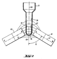
- Fig. 1 shows a recording station for recording a Reaction vessel, which is a suspension of magnetic microparticles contains, the receiving station a separating device for separating contains magnetic microparticles and wherein the separating device there are two magnets between which the reaction vessel is located, characterized in that the magnets 41 and 42 with respect to the Reaction vessel 8 are diametrically opposite and the pole axes 47 of the Magnets 41 and 42 and the longitudinal axis 48 of the reaction vessel 8 a form an acute angle ( ⁇ ).
- the angle ( ⁇ ) is 45 degrees.
- the magnets 41 and 42 are connected to a magnet holder 38, which has a groove 37.
- the magnets 41 and 42 and the magnet holder 38 are part of one Recording station, which is located in a rotor magazine 18.
- the upper edge 46 of the magnets 41 and 42 is below the Suspension surface 51 on which the pole axes 47 of the magnets 41 and 42 cut.
- the magnetic microparticles 27 will be on two diametrically opposite wall areas 28 inside the Reaction vessels 8 which are closest to the magnets 41, 42, deposited.
- the deposits occur in a local area, which ensures that at different filling levels of the Reaction vessel in the course of the test implementation of the Liquid level is always above the deposits 27 and thereby a resuspension can be carried out reliably.
- FIG. 2 shows the deposits of the magnetic microparticles 27 the inner wall 28 of the reaction vessel 8 under the influence of a magnetic Field in a further arrangement of the magnets 41 according to the invention and 42.
- the field lines of the individual magnets are shown schematically.
- the Angle ( ⁇ ) that the polar axis 47 with the longitudinal axis 48 of the Reaction vessel 8 forms is 45 degrees.
- the processing stations 21-25 contain a magnet arrangement 39 consisting of two pairs of magnets 41 and 42, both the 1 with the magnets 41 and 42 as well 8 with the magnets 61 and 62 is possible.
- the Magnets 41 and 42 are in relation to the circle diameter of the Rotor magazine 18 arranged along radii that form an acute angle ( ⁇ ) form. The angle ( ⁇ ) is 20 degrees. Between the magnets 41 and 42 are the reaction vessels 8 in the groove 37 of the magnet holder 38. Die Magnet arrangements 39 are each at an angle of 60 degrees from one another spaced.
- reaction vessels 8 show an overall perspective view of the rotor magazine 18.
- the processing stations 21-26 can be seen. You can see that the Longitudinal axes 48 of the reaction vessels 8 run parallel to the rotor axis of rotation. The bottom 19 of the reaction vessels 8 lies over the groove 37 of the magnet holder 38. 12 reaction vessels 8 are in 6 groups of two in the edge area of the Rotor 18 arranged on a common pitch circle. everyone The group of two is spaced 60 degrees apart.
- Fig. 5 shows a section through a separation device, of Processing station 22 to 26 with the reaction vessels 8. Die Longitudinal axes 48 of the reaction vessels 8 run parallel to the rotor axis of rotation.
- Processing station 22 contains magnets 41 and 42, while Processing station 26 contains no magnets and for resuspension of the serves magnetic microparticles.
- the rotor magazine 18 is in a Magnet holder 38 mounted shaft 43 and a toothed belt drive 44 with connected to a drive motor 45.
- the drive motor 45 can be controlled in cycles that the Reaction vessels 8 each in the corresponding processing stations stand as long as the required processes require.
- the The rotor magazine rotates 30 degrees with each transport cycle. Through the always identical magnet arrangement in the different stations the magnetic microparticles always in identical areas on the Inner wall of the reaction vessel collected.
- FIG. 6 shows a washing device 11 according to the invention, which the rotor magazine 18 and a holder 31 with a resuspension and Contains aspiration device. You can see that again Processing stations 21-26.
- the aspiration used in the processing stations 25 and 26 and resuspension devices are fixed in a holder 31 and via capillary tubes 32 to a supply system (pump, Reservoir etc.) connected.
- the holder 31 is a two-armed Lever formed, the injection nozzles 29 at the one lever end 33 and the aspiration cannulas 35 are arranged on its other lever arm 34 are.
- the lever arm is pivotable about its axis of rotation 36 as well can be lowered vertically. This adjustment is in Fig. 6 with the arrows Pf1, Pf2 indicated.
- the size of the angle adjustment, the distance of the injection and aspiration elements and their arrangement on the corresponding Lever ends of the holder are coordinated so that the Injection elements 29 with those in the processing station 26 or Aspiration cannula 35 with those located in the processing stations 25 Reaction vessels 8 can be brought into alignment for processing.
- the elements that are not in the working position are located above a drainer.
- FIG. 7 shows an overview of the analytical device according to the invention, which is designed, for example, to carry out DNA detections.
- the analyzer 1 contains: Devices for performing the above-mentioned DNA detections, here for example two racks 3, 4 with reagents on a shaking table 5, three racks 7 with disposable reagent containers 8, a temperature-controlled incubator 9, a washing device 11 and a photometer 12.
- the sample and reagent transfer as well as the reaction vessel transfer is moved by one in the x-y coordinate system Transfer head 13 allows a pipetting device 14 and has a reaction vessel gripper 15, both movable in the z direction.
- the washing device can via the gripper 15 Transfer device 13 can be loaded and unloaded.
- process parameters Via an operating level 16 and / or a barcode reading pen 17 process parameters can be entered.
- the CPU controls and coordinates all process operations.
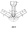
- FIG. 8 shows a further embodiment according to the invention.
- the magnets 61 and 62 shown in FIG. 8 are different from FIG. 1 rotated by 180 °. North and south poles of the magnets 61 shown in FIG. 8 and 62 lie diametrically in the bottom region 19 of the reaction vessel 8 across from.
- the pole axes 67 of the magnets 61 and 62 and the longitudinal axis 48 of the reaction vessel 8 form an acute angle ( ⁇ ) and intersect in the area of the bottom 19.
- the magnets 61 and 62 are, as in FIG. 1 connected to the magnet holder 38, which has a groove 37 into which the Bottom 19 of the reaction vessel 8 protrudes.
- the magnetic Microparticles 27 are diametrically opposed to two Wall areas 28 inside the reaction vessels 8 in the area of Bottom 19 focused.
- the magnets 61 and 62 and the magnet holder 38 are Parts of a receiving station, which is located in a rotor magazine 18.
- FIG. 9 shows the deposits of the magnetic microparticles 27 the inner wall 28 of the reaction vessel 8 under the influence of a magnetic Field in a further arrangement of the magnets 61 according to the invention and 62.
- the field lines of the individual magnets are shown schematically.
- the Angle ( ⁇ ) that the polar axis 67 with the longitudinal axis 48 of the Reaction vessel 8 forms is 45 degrees.
- the two magnet arrangements described above i. H. the Arrangement according to FIG. 1 and the arrangement according to FIG. 8 can also can be used in combination.
- the special magnets 41, 42, 61, 62 have the advantage that they can be used for both magnet arrangements can.
Landscapes
- Health & Medical Sciences (AREA)
- Immunology (AREA)
- Life Sciences & Earth Sciences (AREA)
- Engineering & Computer Science (AREA)
- Molecular Biology (AREA)
- Biomedical Technology (AREA)
- Chemical & Material Sciences (AREA)
- Hematology (AREA)
- Urology & Nephrology (AREA)
- Food Science & Technology (AREA)
- Biochemistry (AREA)
- Cell Biology (AREA)
- Biotechnology (AREA)
- Medicinal Chemistry (AREA)
- Physics & Mathematics (AREA)
- Analytical Chemistry (AREA)
- Microbiology (AREA)
- General Health & Medical Sciences (AREA)
- General Physics & Mathematics (AREA)
- Pathology (AREA)
- Automatic Analysis And Handling Materials Therefor (AREA)
- Sampling And Sample Adjustment (AREA)
- Devices For Use In Laboratory Experiments (AREA)
- Soft Magnetic Materials (AREA)
- Investigating Or Analyzing Materials By The Use Of Magnetic Means (AREA)
Description
Einrichtungen zur Durchführung obengenannter DNA-Detektionen, hier z.B. zwei Racks 3, 4 mit Reagenzien auf einem Schütteltisch 5, drei Racks 7 mit Einwegreagenzbehältern 8, ein temperierbarer Inkubator 9, eine Wascheinrichtung 11 und ein Photometer 12.
Claims (10)
- Analysengerät, welchesein Reaktionsgefäss (8) und wenigstens eine Bearbeitungsstation zur Aufnahme eines Reaktionsgefässes umfasst,wobei das Reaktionsgefäss (8) einen länglichen unteren Teil mit im wesentlichen konstanter Querschnitt, einen geschlossenen Boden (19), und eine Längsachse (48) hat, und eine Suspension magnetischer Mikropartikel (27) enthält, welche Suspension eine Oberfläche (51) hat,wobei die wenigstens eine Bearbeitungsstation eine Trennvorrichtung zum Abtrennen der magnetischen Mikropartikel enthält,wobei die Trennvorrichtung aus zwei Magneten (41, 42 bzw. 61, 62) besteht, und ein länglicher Bereich des unteren Teils des Reaktionsgefässes (8) zwischen dem Nordpol des einen Magneten (41, 61) und dem Südpol des anderen Magneten (42, 62) angeordnet ist, wobei der Nordpol des einen Magneten (41, 61) gegenüber dem Südpol des anderen Magneten (42, 62) liegt, undwobei sich zwischen jedem der Magneten und dem Reaktionsgefäss ausschliesslich ein Luftspalt befindet,welches Analysengerät dadurch gekennzeichnet ist, dassdie Polachse (47) jedes der Magneten (41, 42) mit der Längsachse (48) des Reaktionsgefässes (8) einen spitzen Winkel α bildet.
- Analysengerät gemäss Anspruch 1, dadurch gekennzeichnet, dass der spitze Winkel α 45 Grad beträgt.
- Analysengerät gemäss Anspruch 1, dadurch gekennzeichnet, dass die Magneten (61, 62) mit einem Magnethalter (38) verbunden sind, der eine Nut (37) besitzt, in die der Boden (19) des Reaktionsgefässes (8) hineinragt.
- Analysengerät gemäss Anspruch 1, dadurch gekennzeichnet, dass die Magneten (41, 42), in bezug auf das Reaktionsgefäss (8) so angeordnet sind, dass die Oberkante (46) der Magnete (41, 42) unterhalb der Suspensionsoberfläche (51) liegt und dass sich die Polachsen (47) der Magnete (41, 42) an der Suspensionsoberfläche (51) schneiden.
- Analysengerät gemäss Anspruch 1, dadurch gekennzeichnet, dass die Magneten (61, 62) in bezug auf das Reaktionsgefäss (8) so angeordnet sind, dass die Pole beider Magnete (61, 62) auf einer Höhe angeordnet sind, die im Bereich des Bodens (19) liegt und dass sich die Polachsen (67) der Magnete (61) und (62) in einem Punkt schneiden, der entlang der Längsachse des Reaktionsgefässes und auf einer Höhe im Bereich des Bodens (19) liegt.
- Analysengerät gemäss Anspruch 1, dadurch gekennzeichnet, dass n Bearbeitungsstationen zur Aufnahme der Reaktionsgefässe auf einem kreisförmigen Rotormagazin (18) angeordnet sind, wobei n eine ganze Zahl zwischen 1 und 20 ist.
- Analysengerät gemäss Anspruch 6, dadurch gekennzeichnet, dass das Rotormagazin (18) Teil einer Wascheinrichtung (11) ist, welche mindestens eine Bearbeitungsstation (25) zur Aspiration, mindestens eine Bearbeitungsstation (26) zur Resuspension von magnetischen Partikeln, und mehrere Bearbeitungsstationen (21-24) zur Trennung von fester und flüssiger Phase enthält, wobei jede der Bearbeitungsstationen zur Trennung (21-24) und zur Aspiration (25) eine Aufnahmestation mit einer Trennvorrichtung gemäss Anspruch 4 oder 5 zum Abtrennen der magnetischen Mikropartikel enthält.
- Analysengerät gemäss Anspruch 6 und 7, dadurch gekennzeichnet, dass die Aufnahmestationen in den Bearbeitungsstationen (21-25) eine paarweise Anordnung (39) von Magneten (41, 42 bzw. 61, 62) enthalten, wobei die Magneten (41, 42 bzw. 61, 62) in bezug auf den Kreisdurchmesser des Rotormagazins (18) entlang Radien angeordnet sind, die einen spitzen Winkel β bilden.
- Analysengerät gemäss Anspruch 8, dadurch gekennzeichnet, dass der Winkel β 20 Grad beträgt.
- Analysengerät gemäss einem der Ansprüche 6-9, dadurch gekennzeichnet, dass das Rotormagazin (18) über eine im Magnethalter (38) gelagerte Welle (43) und einen Zahnriemenantrieb (44) mit einem Antriebsmotor (45) verbunden ist, der derart taktweise steuerbar ist, dass das Reaktionsgefäss (8) jeweils in den Bearbeitungsstationen (21-26) zu stehen kommt.
Applications Claiming Priority (3)
| Application Number | Priority Date | Filing Date | Title |
|---|---|---|---|
| CH280193 | 1993-09-17 | ||
| CH280193 | 1993-09-17 | ||
| CH2801/93 | 1993-09-17 |
Publications (2)
| Publication Number | Publication Date |
|---|---|
| EP0644425A1 EP0644425A1 (de) | 1995-03-22 |
| EP0644425B1 true EP0644425B1 (de) | 2002-01-30 |
Family
ID=4241900
Family Applications (1)
| Application Number | Title | Priority Date | Filing Date |
|---|---|---|---|
| EP94113653A Expired - Lifetime EP0644425B1 (de) | 1993-09-17 | 1994-09-01 | Analysengerät mit einer Vorrichtung zum Abtrennen magnetischer Mikropartikel |
Country Status (7)
| Country | Link |
|---|---|
| US (1) | US5705062A (de) |
| EP (1) | EP0644425B1 (de) |
| JP (1) | JP2825768B2 (de) |
| AT (1) | ATE212723T1 (de) |
| CA (1) | CA2131843A1 (de) |
| DE (1) | DE59410037D1 (de) |
| ES (1) | ES2170083T3 (de) |
Cited By (1)
| Publication number | Priority date | Publication date | Assignee | Title |
|---|---|---|---|---|
| US9150908B2 (en) | 1998-05-01 | 2015-10-06 | Gen-Probe Incorporated | Method for detecting the presence of a nucleic acid in a sample |
Families Citing this family (85)
| Publication number | Priority date | Publication date | Assignee | Title |
|---|---|---|---|---|
| US6537817B1 (en) | 1993-05-31 | 2003-03-25 | Packard Instrument Company | Piezoelectric-drop-on-demand technology |
| DE4429155A1 (de) * | 1994-08-17 | 1996-02-22 | Hans Schiesl | Meßanordnung und Verfahren zur Durchführung luminometrischer Reihenanalysen sowie Mehrfachküvette zur Aufnahme von Flüssigkeitsproben hierfür |
| US6884357B2 (en) | 1995-02-21 | 2005-04-26 | Iqbal Waheed Siddiqi | Apparatus and method for processing magnetic particles |
| US20030127396A1 (en) * | 1995-02-21 | 2003-07-10 | Siddiqi Iqbal Waheed | Apparatus and method for processing magnetic particles |
| DE19512368A1 (de) * | 1995-04-01 | 1996-10-02 | Boehringer Mannheim Gmbh | System zur Freisetzung und Isolierung von Nukleinsäuren |
| US6919175B1 (en) | 1995-04-01 | 2005-07-19 | Roche Diagnostics Gmbh | System for releasing and isolating nucleic acids |
| US6299839B1 (en) * | 1995-08-31 | 2001-10-09 | First Medical, Inc. | System and methods for performing rotor assays |
| JP3682302B2 (ja) * | 1996-05-20 | 2005-08-10 | プレシジョン・システム・サイエンス株式会社 | 分注機による磁性体粒子の制御方法およびその装置 |
| US6106784A (en) * | 1997-09-26 | 2000-08-22 | Applied Chemical & Engineering Systems, Inc. | Thawing station |
| US6558947B1 (en) | 1997-09-26 | 2003-05-06 | Applied Chemical & Engineering Systems, Inc. | Thermal cycler |
| DE69839294T2 (de) * | 1997-09-29 | 2009-04-09 | F. Hoffmann-La Roche Ag | Gerät zur Abscheidung magnetischer Teilchen |
| EP1065001B1 (de) * | 1998-03-19 | 2008-09-24 | Precision System Science Co., Ltd. | Apparat zur integration von magnetteilchen - verarbeitung und steuerungsverfahren |
| US8337753B2 (en) | 1998-05-01 | 2012-12-25 | Gen-Probe Incorporated | Temperature-controlled incubator having a receptacle mixing mechanism |
| AU4093699A (en) * | 1998-05-22 | 1999-12-13 | Nichols Institute Diagnostics | Magnetic particle suspending device, apparatus and methods for using same |
| DE19823719B4 (de) * | 1998-05-27 | 2011-12-15 | MAX-PLANCK-Gesellschaft zur Förderung der Wissenschaften e.V. | Verfahren zum Aufkonzentrieren von Substanzen |
| EP0977037B1 (de) * | 1998-07-31 | 2005-08-31 | Tecan Trading AG | Magnetseparator |
| US6776174B2 (en) * | 1998-08-21 | 2004-08-17 | Paul E. Nisson | Apparatus for washing magnetic particles |
| US6357907B1 (en) * | 1999-06-15 | 2002-03-19 | V & P Scientific, Inc. | Magnetic levitation stirring devices and machines for mixing in vessels |
| ATE269175T1 (de) * | 1999-10-15 | 2004-07-15 | Packard Instrument Co Inc | Piezoelektrische drop-on-demand technik und spüllung von kapillaren |
| US7390459B2 (en) * | 1999-12-13 | 2008-06-24 | Illumina, Inc. | Oligonucleotide synthesizer |
| US6663832B2 (en) * | 1999-12-13 | 2003-12-16 | Illumina, Inc. | Oligonucleotide synthesizer |
| US6672458B2 (en) * | 2000-05-19 | 2004-01-06 | Becton, Dickinson And Company | System and method for manipulating magnetically responsive particles fluid samples to collect DNA or RNA from a sample |
| DE10156790A1 (de) * | 2001-11-19 | 2003-06-18 | Chemagen Biopolymer Technologi | Vorrichtung und Verfahren zum Behandeln von Magnetpartikeln |
| WO2003086637A1 (en) * | 2002-04-12 | 2003-10-23 | Instrumentation Laboratory Company | Immunoassay probe |
| US7601491B2 (en) | 2003-02-06 | 2009-10-13 | Becton, Dickinson And Company | Pretreatment method for extraction of nucleic acid from biological samples and kits therefor |
| US20040157219A1 (en) * | 2003-02-06 | 2004-08-12 | Jianrong Lou | Chemical treatment of biological samples for nucleic acid extraction and kits therefor |
| US20050239091A1 (en) * | 2004-04-23 | 2005-10-27 | Collis Matthew P | Extraction of nucleic acids using small diameter magnetically-responsive particles |
| US8211386B2 (en) | 2004-06-08 | 2012-07-03 | Biokit, S.A. | Tapered cuvette and method of collecting magnetic particles |
| EP1621890A1 (de) * | 2004-07-26 | 2006-02-01 | bioMerieux B.V. | Gerät und Methode zur Separation, Mischung und Konzentrierung magnetischer Partikel mit Flüssigkeiten und deren Verwendungen in Reinigungsmethoden |
| EP1774334B1 (de) * | 2004-08-03 | 2017-10-04 | Becton, Dickinson and Company | Verwendung von magnetischem material zur direkten isolierung von substanzen und fraktionierung von proben, die mehrere komponenten enthalten |
| EP1773865A1 (de) * | 2004-08-03 | 2007-04-18 | Becton, Dickinson and Company | Verwendung von magnetischem material zum fraktionieren von proben |
| US7964413B2 (en) | 2005-03-10 | 2011-06-21 | Gen-Probe Incorporated | Method for continuous mode processing of multiple reaction receptacles in a real-time amplification assay |
| US20100213136A1 (en) * | 2005-06-23 | 2010-08-26 | Koninklijke Philips Electronics, N.V. | Apparatus for moving magnetic particles |
| EP1839756A1 (de) * | 2006-03-31 | 2007-10-03 | F.Hoffmann-La Roche Ag | Gerät zur Abscheidung magnetischer Teilchen aus teilchenhaltigen Flüssigkeiten, und einer Gruppe von Behältern zur Verwendung mit einem solchen Gerät |
| JP2007319735A (ja) * | 2006-05-30 | 2007-12-13 | Fuji Xerox Co Ltd | マイクロリアクター装置及び微小流路の洗浄方法 |
| US8246919B2 (en) | 2006-09-21 | 2012-08-21 | Abbott Laboratories | Specimen sample rack |
| US8795609B2 (en) | 2007-02-08 | 2014-08-05 | Biokit, S.A. | Magnetic particle washing station |
| GB0724404D0 (en) * | 2007-05-29 | 2008-01-30 | Invitrogen Dynal As | A sample vessel retaining portion |
| US9199247B2 (en) * | 2007-05-29 | 2015-12-01 | Invitrogen Dynal As | Magnetic separation rack |
| US7883265B2 (en) * | 2007-06-01 | 2011-02-08 | Applied Biosystems, Llc | Devices, systems, and methods for preparing emulsions |
| EP2171098B1 (de) * | 2007-06-29 | 2018-03-28 | Becton, Dickinson and Company | Verfahren zur extraktion und aufreinigung von bestandteilen biologischer proben |
| TWI325337B (en) * | 2007-07-26 | 2010-06-01 | Ind Tech Res Inst | Magnetic separation device |
| TWI316874B (en) * | 2007-07-26 | 2009-11-11 | Ind Tech Res Inst | Magnetic separation device |
| CN101377456B (zh) * | 2007-08-27 | 2010-12-08 | 财团法人工业技术研究院 | 磁性转换分离装置 |
| JP4586054B2 (ja) * | 2007-08-31 | 2010-11-24 | 株式会社日立ハイテクノロジーズ | 自動分析装置 |
| DE102008057317A1 (de) | 2007-11-13 | 2009-09-10 | Stratec Biomedical Systems Ag | Vorrichtung und Verfahren zur Aufreinigung von Biomolekülen |
| EP2208531A1 (de) * | 2008-12-30 | 2010-07-21 | Atonomics A/S | Verteilung von Partikeln in einem Kapillarkanal durch Anwendung eines Magnetfelds |
| TWI429475B (zh) * | 2009-10-30 | 2014-03-11 | Rbc Bioscience Corp | 一體式反應匣 |
| KR20130029128A (ko) | 2010-07-23 | 2013-03-21 | 베크만 컬터, 인코포레이티드 | 실시간 pcr용 용기 |
| US9046507B2 (en) | 2010-07-29 | 2015-06-02 | Gen-Probe Incorporated | Method, system and apparatus for incorporating capacitive proximity sensing in an automated fluid transfer procedure |
| US9144801B2 (en) | 2010-08-31 | 2015-09-29 | Abbott Laboratories | Sample tube racks having retention bars |
| EP2678664B1 (de) | 2011-02-24 | 2019-08-07 | Gen-Probe Incorporated | Systeme und verfahren zur unterscheidung optischer signale mit verschiedenen modulationsfrequenzen bei einem optischen signaldetektor |
| JP6072033B2 (ja) | 2011-07-29 | 2017-02-01 | コーニング インコーポレイテッド | 磁気分離装置及び方法 |
| KR102040996B1 (ko) | 2011-11-07 | 2019-11-05 | 베크만 컬터, 인코포레이티드 | 로봇식 아암 |
| BR112014010955A2 (pt) | 2011-11-07 | 2017-06-06 | Beckman Coulter Inc | sistema e método para processar amostras |
| JP6062449B2 (ja) | 2011-11-07 | 2017-01-18 | ベックマン コールター, インコーポレイテッド | 標本コンテナ検出 |
| BR112014011044A2 (pt) | 2011-11-07 | 2017-04-25 | Beckman Coulter Inc | amortecimento magnético para sistema de transporte de espécime |
| KR20140092375A (ko) | 2011-11-07 | 2014-07-23 | 베크만 컬터, 인코포레이티드 | 원심분리기 시스템 및 작업 흐름 |
| EP2776846B1 (de) | 2011-11-07 | 2019-08-21 | Beckman Coulter, Inc. | Aliquotierungssystem und arbeitsablauf |
| USD706946S1 (en) | 2011-12-22 | 2014-06-10 | Eppendorf Ag | Pipette |
| USD709623S1 (en) | 2011-12-22 | 2014-07-22 | Eppendorf Ag | Pipette barrel |
| CN103376333B (zh) * | 2012-04-17 | 2015-09-16 | 深圳迈瑞生物医疗电子股份有限公司 | 全自动生化分析仪 |
| US9199870B2 (en) | 2012-05-22 | 2015-12-01 | Corning Incorporated | Electrostatic method and apparatus to form low-particulate defect thin glass sheets |
| JP6207933B2 (ja) * | 2012-08-31 | 2017-10-04 | 東芝メディカルシステムズ株式会社 | 検体検査装置 |
| CN102954954B (zh) * | 2012-09-19 | 2014-07-16 | 东南大学 | 基于磁分离的多样本多位点高通量核酸分析系统 |
| WO2014144627A1 (en) | 2013-03-15 | 2014-09-18 | Abbott Laboratories | Automated diagnostic analyzers having rear accessible track systems and related methods |
| ES2970108T3 (es) | 2013-03-15 | 2024-05-27 | Abbott Lab | Analizadores de diagnóstico con carruseles de pretratamiento y métodos relacionados |
| JP6351703B2 (ja) | 2013-03-15 | 2018-07-04 | アボット・ラボラトリーズAbbott Laboratories | 垂直配置カルーセルを有する自動診断分析装置および関連方法 |
| US9504981B2 (en) * | 2013-05-15 | 2016-11-29 | True Health Diagnostics Llc | Methods for purifying nucleic acids and devices thereof |
| EP2881740B1 (de) * | 2013-12-03 | 2019-02-13 | Immunodiagnostic Systems Limited | Verfahren zur Quantifizierung eines Analyts und automatische analytische Vorrichtung zur Durchführung des besagten Verfahrens |
| USD805651S1 (en) | 2013-12-12 | 2017-12-19 | Eppendorf Ag | Flange for a pipette adapter |
| WO2015126340A1 (en) * | 2014-02-18 | 2015-08-27 | Anatoli̇a Tani Ve Bi̇yoteknoloji̇ Ürünleri̇ Araştirma Geli̇şti̇rme Sanayi̇ Ve Ti̇caret Anoni̇m Şi̇rketi̇ | A laboratory equipment utilized to isolate nucleic acids manually via magnetic particles and to prepare them for molecular genetic analyses |
| US9663780B2 (en) | 2014-10-15 | 2017-05-30 | Alpaqua Engineering, LLC | Solid-core ring-magnet |
| US10094842B2 (en) | 2014-10-17 | 2018-10-09 | Shenzhen Mindray Bio-Medical Electronics Co., Ltd. | Automatic biochemical analyzer |
| JP6472973B2 (ja) | 2014-10-24 | 2019-02-20 | 日本電子株式会社 | 自動分析装置及び分離洗浄方法 |
| AU2016200047A1 (en) * | 2015-01-07 | 2016-07-21 | Personal Genomics, Inc. | Oriented Loading Systems And Method For Orienting A Particle Loaded In A Well |
| CZ2015141A3 (cs) * | 2015-02-26 | 2016-09-14 | Univerzita PalackĂ©ho v Olomouci | Zařízení pro magnetickou separaci feromagnetických částic, sada pro magnetickou separaci částic, způsob separace magnetických částic z roztoku a použití zařízení nebo sady pro magnetickou separaci částic |
| EP3262397B1 (de) * | 2015-02-27 | 2022-06-08 | Hycor Biomedical, LLC | Vorrichtungen zum suspendieren und waschen des inhalts mehrerer küvetten |
| US10427162B2 (en) | 2016-12-21 | 2019-10-01 | Quandx Inc. | Systems and methods for molecular diagnostics |
| US11242519B2 (en) | 2018-08-23 | 2022-02-08 | Alpaqua Engineering, LLC | Discontinuous wall hollow core magnet |
| MA53439A (fr) | 2018-08-23 | 2021-06-30 | Alpaqua Eng Llc | Aimant à noyau solide |
| US11684926B2 (en) * | 2019-07-14 | 2023-06-27 | Zhuhai Sanmed Biotech Ltd. | System and processes for isolation and enrichment by magnetic separation |
| WO2021157216A1 (ja) | 2020-02-07 | 2021-08-12 | 積水メディカル株式会社 | 自動分析装置 |
| US12372497B2 (en) | 2021-08-18 | 2025-07-29 | Alpaqua Engineering, LLC | Plate cushion device having a compression gap lock |
| DE202021105458U1 (de) * | 2021-10-08 | 2023-01-24 | Sanolibio Co., Ltd. | Vorrichtung zur magnetischen Aufreinigung biologischer Proben |
Family Cites Families (14)
| Publication number | Priority date | Publication date | Assignee | Title |
|---|---|---|---|---|
| DE3102029A1 (de) * | 1981-01-22 | 1982-08-26 | Europäisches Laboratorium für Molekularbiologie (EMBL), 6900 Heidelberg | Vorrichtung zum abtrennen ferromagnetischer partikel |
| JPS5852718B2 (ja) * | 1981-12-01 | 1983-11-24 | 清進産業株式会社 | 廃水処理における懸濁物の分離方法と装置 |
| CA1220168A (en) * | 1983-09-09 | 1987-04-07 | Henry J. Rahn | Magnetic separator for solid phase immunoassays |
| JPS62133354A (ja) * | 1985-12-06 | 1987-06-16 | Nitsuteku:Kk | Eia分析装置の撹拌装置 |
| ATE108556T1 (de) * | 1987-11-16 | 1994-07-15 | Gene Trak Systems | Magnetische trennvorrichtung und verfahren zur anwendung in heterogenen prüfungen. |
| JPH01136068A (ja) * | 1987-11-20 | 1989-05-29 | Hitachi Ltd | 自動分析装置 |
| US4895650A (en) * | 1988-02-25 | 1990-01-23 | Gen-Probe Incorporated | Magnetic separation rack for diagnostic assays |
| JPH02307059A (ja) * | 1989-05-23 | 1990-12-20 | Seiko Instr Inc | 反応容器 |
| IL94212A0 (en) * | 1989-07-24 | 1991-01-31 | Tri Tech Partners And Triton B | Automated analytical apparatus and method |
| JP2878785B2 (ja) * | 1990-05-17 | 1999-04-05 | 株式会社東芝 | 免疫分析システム |
| WO1992005443A1 (en) * | 1990-09-15 | 1992-04-02 | Medical Research Council | Reagent separation |
| JP2548626B2 (ja) * | 1990-11-21 | 1996-10-30 | 三井製薬工業株式会社 | 免疫自動分析装置 |
| JPH04271823A (ja) * | 1991-02-26 | 1992-09-28 | Kyoto Daiichi Kagaku:Kk | セル内液体の撹拌装置 |
| EP0589636B1 (de) * | 1992-09-24 | 2000-08-02 | Amersham Pharmacia Biotech UK Limited | Verfahren und Vorrichtung zur magnetischen Abscheidung |
-
1994
- 1994-09-01 DE DE59410037T patent/DE59410037D1/de not_active Expired - Lifetime
- 1994-09-01 ES ES94113653T patent/ES2170083T3/es not_active Expired - Lifetime
- 1994-09-01 EP EP94113653A patent/EP0644425B1/de not_active Expired - Lifetime
- 1994-09-01 AT AT94113653T patent/ATE212723T1/de not_active IP Right Cessation
- 1994-09-07 US US08/301,857 patent/US5705062A/en not_active Expired - Lifetime
- 1994-09-12 CA CA002131843A patent/CA2131843A1/en not_active Abandoned
- 1994-09-16 JP JP6221895A patent/JP2825768B2/ja not_active Expired - Fee Related
Cited By (2)
| Publication number | Priority date | Publication date | Assignee | Title |
|---|---|---|---|---|
| US9150908B2 (en) | 1998-05-01 | 2015-10-06 | Gen-Probe Incorporated | Method for detecting the presence of a nucleic acid in a sample |
| US9598723B2 (en) | 1998-05-01 | 2017-03-21 | Gen-Probe Incorporated | Automated analyzer for performing a nucleic acid-based assay |
Also Published As
| Publication number | Publication date |
|---|---|
| DE59410037D1 (de) | 2002-03-14 |
| US5705062A (en) | 1998-01-06 |
| ATE212723T1 (de) | 2002-02-15 |
| EP0644425A1 (de) | 1995-03-22 |
| JPH07181188A (ja) | 1995-07-21 |
| ES2170083T3 (es) | 2002-08-01 |
| CA2131843A1 (en) | 1995-03-18 |
| JP2825768B2 (ja) | 1998-11-18 |
Similar Documents
| Publication | Publication Date | Title |
|---|---|---|
| EP0644425B1 (de) | Analysengerät mit einer Vorrichtung zum Abtrennen magnetischer Mikropartikel | |
| EP0644426B1 (de) | Analysengerät mit einer Vorrichtung zur Suspension von Partikeln und ein Verfahren zur Durchführung der Suspension | |
| DE69839294T2 (de) | Gerät zur Abscheidung magnetischer Teilchen | |
| EP1446668B1 (de) | Vorrichtung und verfahren zum behandeln von magnetpartikeln | |
| EP2030689B1 (de) | Mikroplatten-Träger mit Magneten | |
| DE69205170T2 (de) | Automatisches geraet mit mehreren linearen bahnen fuer duerchfuehrung von immunologischen testen. | |
| EP1843854B1 (de) | Vorrichtung und verfahren zum abtrennen von magnetischen oder magnetisierbaren partikeln aus einer flüssigkeit | |
| DE69504574T2 (de) | Magnetscheideverfahren und -vorrichtung bei Gebrauch einer Pipette. | |
| DE69429840T2 (de) | Transportsystem für ein Analysengerät für Flüssigkeiten | |
| DE69329135T2 (de) | Verfahren und Vorrichtung zur magnetischen Abscheidung | |
| DE60000539T2 (de) | Vorrichtung und verfahren zur übertragung von kleinen substanzvolumen | |
| DE69827678T2 (de) | Reaktionsbehälterapparat | |
| DE68911628T2 (de) | Verfahren zur automatischen Bearbeitung von magnetischen Festphasen-Reagenzien. | |
| EP0408804B1 (de) | Analysegerät für heterogene immunologische Tests | |
| EP1644120B1 (de) | Vorrichtung und verfahren zum abtrennen von magnetischen oder magnetisierbaren partikeln aus einer flüssigkeit | |
| DE10057396C1 (de) | Verfahren zum Abtrennen eines dispergierten oder gelösten Stoffes und Magnetseparator | |
| DE69833846T2 (de) | Vorrichtung zum Befördern von Komponenten innerhalb eines automatischen Analysesystems | |
| DE60207564T2 (de) | Behandlungsverfahren für magnetische teilchen und bioanalyse-apparat mit magnetverwendung | |
| EP0691541A2 (de) | Vorrichtung und Verfahren zum Abscheiden von magnetischen Mikropartikeln | |
| EP1919625A1 (de) | Vorrichtung und verfahren zum abtrennen von magnetischen partikeln aus einer flüssigkeit | |
| EP0048452A1 (de) | Verfahren zur Verteilung von Proben aus Primärgefässen | |
| DE3877453T2 (de) | Analysator mit vom inkubator separierter waschstation. | |
| DE10063984A1 (de) | Vorrichtungen zur magnetischen Abtrennung von Magnetpartikeln | |
| EP1291647B1 (de) | Magnetische Greifvorrichtung zum Wechseln von länglichen Proben in einem Röntgen-Analysegerät | |
| EP3270166A1 (de) | Greifvorrichtung zum transport von flüssigkeitsbehältern in einem automatischen analysegerät |
Legal Events
| Date | Code | Title | Description |
|---|---|---|---|
| PUAI | Public reference made under article 153(3) epc to a published international application that has entered the european phase |
Free format text: ORIGINAL CODE: 0009012 |
|
| 17P | Request for examination filed |
Effective date: 19940901 |
|
| AK | Designated contracting states |
Kind code of ref document: A1 Designated state(s): AT BE CH DE DK ES FR GB GR IE IT LI LU NL PT |
|
| 17Q | First examination report despatched |
Effective date: 19971128 |
|
| GRAG | Despatch of communication of intention to grant |
Free format text: ORIGINAL CODE: EPIDOS AGRA |
|
| GRAG | Despatch of communication of intention to grant |
Free format text: ORIGINAL CODE: EPIDOS AGRA |
|
| GRAG | Despatch of communication of intention to grant |
Free format text: ORIGINAL CODE: EPIDOS AGRA |
|
| GRAH | Despatch of communication of intention to grant a patent |
Free format text: ORIGINAL CODE: EPIDOS IGRA |
|
| GRAH | Despatch of communication of intention to grant a patent |
Free format text: ORIGINAL CODE: EPIDOS IGRA |
|
| GRAA | (expected) grant |
Free format text: ORIGINAL CODE: 0009210 |
|
| REG | Reference to a national code |
Ref country code: GB Ref legal event code: IF02 |
|
| AK | Designated contracting states |
Kind code of ref document: B1 Designated state(s): AT BE CH DE DK ES FR GB GR IE IT LI LU NL PT |
|
| PG25 | Lapsed in a contracting state [announced via postgrant information from national office to epo] |
Ref country code: IE Free format text: LAPSE BECAUSE OF FAILURE TO SUBMIT A TRANSLATION OF THE DESCRIPTION OR TO PAY THE FEE WITHIN THE PRESCRIBED TIME-LIMIT Effective date: 20020130 Ref country code: GR Free format text: LAPSE BECAUSE OF FAILURE TO SUBMIT A TRANSLATION OF THE DESCRIPTION OR TO PAY THE FEE WITHIN THE PRESCRIBED TIME-LIMIT Effective date: 20020130 |
|
| REF | Corresponds to: |
Ref document number: 212723 Country of ref document: AT Date of ref document: 20020215 Kind code of ref document: T |
|
| REG | Reference to a national code |
Ref country code: CH Ref legal event code: EP |
|
| GBT | Gb: translation of ep patent filed (gb section 77(6)(a)/1977) |
Effective date: 20020130 |
|
| REF | Corresponds to: |
Ref document number: 59410037 Country of ref document: DE Date of ref document: 20020314 |
|
| REG | Reference to a national code |
Ref country code: CH Ref legal event code: NV Representative=s name: VENTOCILLA PATENT AG |
|
| REG | Reference to a national code |
Ref country code: IE Ref legal event code: FG4D Free format text: GERMAN |
|
| PG25 | Lapsed in a contracting state [announced via postgrant information from national office to epo] |
Ref country code: PT Free format text: LAPSE BECAUSE OF FAILURE TO SUBMIT A TRANSLATION OF THE DESCRIPTION OR TO PAY THE FEE WITHIN THE PRESCRIBED TIME-LIMIT Effective date: 20020430 Ref country code: DK Free format text: LAPSE BECAUSE OF FAILURE TO SUBMIT A TRANSLATION OF THE DESCRIPTION OR TO PAY THE FEE WITHIN THE PRESCRIBED TIME-LIMIT Effective date: 20020430 |
|
| ET | Fr: translation filed | ||
| REG | Reference to a national code |
Ref country code: ES Ref legal event code: FG2A Ref document number: 2170083 Country of ref document: ES Kind code of ref document: T3 |
|
| REG | Reference to a national code |
Ref country code: IE Ref legal event code: FD4D |
|
| PG25 | Lapsed in a contracting state [announced via postgrant information from national office to epo] |
Ref country code: LU Free format text: LAPSE BECAUSE OF NON-PAYMENT OF DUE FEES Effective date: 20020901 Ref country code: AT Free format text: LAPSE BECAUSE OF NON-PAYMENT OF DUE FEES Effective date: 20020901 |
|
| PG25 | Lapsed in a contracting state [announced via postgrant information from national office to epo] |
Ref country code: BE Free format text: LAPSE BECAUSE OF NON-PAYMENT OF DUE FEES Effective date: 20020930 |
|
| PLBQ | Unpublished change to opponent data |
Free format text: ORIGINAL CODE: EPIDOS OPPO |
|
| PLBI | Opposition filed |
Free format text: ORIGINAL CODE: 0009260 |
|
| PLBF | Reply of patent proprietor to notice(s) of opposition |
Free format text: ORIGINAL CODE: EPIDOS OBSO |
|
| 26 | Opposition filed |
Opponent name: VON MENGES, DR. ALBRECHT Effective date: 20021030 |
|
| NLR1 | Nl: opposition has been filed with the epo |
Opponent name: VON MENGES, DR. ALBRECHT |
|
| BERE | Be: lapsed |
Owner name: F. *HOFFMANN-LA ROCHE A.G. Effective date: 20020930 |
|
| PLBF | Reply of patent proprietor to notice(s) of opposition |
Free format text: ORIGINAL CODE: EPIDOS OBSO |
|
| PLBB | Reply of patent proprietor to notice(s) of opposition received |
Free format text: ORIGINAL CODE: EPIDOSNOBS3 |
|
| PLBP | Opposition withdrawn |
Free format text: ORIGINAL CODE: 0009264 |
|
| PLBD | Termination of opposition procedure: decision despatched |
Free format text: ORIGINAL CODE: EPIDOSNOPC1 |
|
| PLBM | Termination of opposition procedure: date of legal effect published |
Free format text: ORIGINAL CODE: 0009276 |
|
| STAA | Information on the status of an ep patent application or granted ep patent |
Free format text: STATUS: OPPOSITION PROCEDURE CLOSED |
|
| 27C | Opposition proceedings terminated |
Effective date: 20050329 |
|
| NLR2 | Nl: decision of opposition |
Effective date: 20050329 |
|
| REG | Reference to a national code |
Ref country code: CH Ref legal event code: NV Representative=s name: ROCHE DIAGNOSTICS AG |
|
| PGFP | Annual fee paid to national office [announced via postgrant information from national office to epo] |
Ref country code: ES Payment date: 20100909 Year of fee payment: 17 Ref country code: CH Payment date: 20100726 Year of fee payment: 17 |
|
| PGFP | Annual fee paid to national office [announced via postgrant information from national office to epo] |
Ref country code: IT Payment date: 20100918 Year of fee payment: 17 Ref country code: FR Payment date: 20100920 Year of fee payment: 17 |
|
| PGFP | Annual fee paid to national office [announced via postgrant information from national office to epo] |
Ref country code: GB Payment date: 20100809 Year of fee payment: 17 |
|
| PGFP | Annual fee paid to national office [announced via postgrant information from national office to epo] |
Ref country code: NL Payment date: 20100909 Year of fee payment: 17 |
|
| REG | Reference to a national code |
Ref country code: NL Ref legal event code: V1 Effective date: 20120401 |
|
| REG | Reference to a national code |
Ref country code: CH Ref legal event code: PL |
|
| GBPC | Gb: european patent ceased through non-payment of renewal fee |
Effective date: 20110901 |
|
| PG25 | Lapsed in a contracting state [announced via postgrant information from national office to epo] |
Ref country code: IT Free format text: LAPSE BECAUSE OF NON-PAYMENT OF DUE FEES Effective date: 20110901 |
|
| REG | Reference to a national code |
Ref country code: FR Ref legal event code: ST Effective date: 20120531 |
|
| PG25 | Lapsed in a contracting state [announced via postgrant information from national office to epo] |
Ref country code: LI Free format text: LAPSE BECAUSE OF NON-PAYMENT OF DUE FEES Effective date: 20110930 Ref country code: CH Free format text: LAPSE BECAUSE OF NON-PAYMENT OF DUE FEES Effective date: 20110930 Ref country code: NL Free format text: LAPSE BECAUSE OF NON-PAYMENT OF DUE FEES Effective date: 20120401 |
|
| PG25 | Lapsed in a contracting state [announced via postgrant information from national office to epo] |
Ref country code: GB Free format text: LAPSE BECAUSE OF NON-PAYMENT OF DUE FEES Effective date: 20110901 Ref country code: FR Free format text: LAPSE BECAUSE OF NON-PAYMENT OF DUE FEES Effective date: 20110930 |
|
| REG | Reference to a national code |
Ref country code: ES Ref legal event code: FD2A Effective date: 20130604 |
|
| PG25 | Lapsed in a contracting state [announced via postgrant information from national office to epo] |
Ref country code: ES Free format text: LAPSE BECAUSE OF NON-PAYMENT OF DUE FEES Effective date: 20110902 |
|
| PGFP | Annual fee paid to national office [announced via postgrant information from national office to epo] |
Ref country code: DE Payment date: 20130930 Year of fee payment: 20 |
|
| REG | Reference to a national code |
Ref country code: DE Ref legal event code: R071 Ref document number: 59410037 Country of ref document: DE |
|
| REG | Reference to a national code |
Ref country code: DE Ref legal event code: R071 Ref document number: 59410037 Country of ref document: DE |
|
| PG25 | Lapsed in a contracting state [announced via postgrant information from national office to epo] |
Ref country code: DE Free format text: LAPSE BECAUSE OF EXPIRATION OF PROTECTION Effective date: 20140902 |