EP0644471B1 - Verfahren und System zur numerischen Steuerung mit Sollwerteinstellung von Beschleunigung und Verzögerung - Google Patents
Verfahren und System zur numerischen Steuerung mit Sollwerteinstellung von Beschleunigung und Verzögerung Download PDFInfo
- Publication number
- EP0644471B1 EP0644471B1 EP94402067A EP94402067A EP0644471B1 EP 0644471 B1 EP0644471 B1 EP 0644471B1 EP 94402067 A EP94402067 A EP 94402067A EP 94402067 A EP94402067 A EP 94402067A EP 0644471 B1 EP0644471 B1 EP 0644471B1
- Authority
- EP
- European Patent Office
- Prior art keywords
- target function
- time
- function
- change
- acceleration
- Prior art date
- Legal status (The legal status is an assumption and is not a legal conclusion. Google has not performed a legal analysis and makes no representation as to the accuracy of the status listed.)
- Expired - Lifetime
Links
Images





Classifications
-
- G—PHYSICS
- G05—CONTROLLING; REGULATING
- G05B—CONTROL OR REGULATING SYSTEMS IN GENERAL; FUNCTIONAL ELEMENTS OF SUCH SYSTEMS; MONITORING OR TESTING ARRANGEMENTS FOR SUCH SYSTEMS OR ELEMENTS
- G05B19/00—Program-control systems
- G05B19/02—Program-control systems electric
- G05B19/18—Numerical control [NC], i.e. automatically operating machines, in particular machine tools, e.g. in a manufacturing environment, so as to execute positioning, movement or co-ordinated operations by means of program data in numerical form
- G05B19/416—Numerical control [NC], i.e. automatically operating machines, in particular machine tools, e.g. in a manufacturing environment, so as to execute positioning, movement or co-ordinated operations by means of program data in numerical form characterised by control of velocity, acceleration or deceleration
-
- G—PHYSICS
- G05—CONTROLLING; REGULATING
- G05B—CONTROL OR REGULATING SYSTEMS IN GENERAL; FUNCTIONAL ELEMENTS OF SUCH SYSTEMS; MONITORING OR TESTING ARRANGEMENTS FOR SUCH SYSTEMS OR ELEMENTS
- G05B2219/00—Program-control systems
- G05B2219/30—Nc systems
- G05B2219/42—Servomotor, servo controller kind till VSS
- G05B2219/42173—Acceleration deceleration
-
- G—PHYSICS
- G05—CONTROLLING; REGULATING
- G05B—CONTROL OR REGULATING SYSTEMS IN GENERAL; FUNCTIONAL ELEMENTS OF SUCH SYSTEMS; MONITORING OR TESTING ARRANGEMENTS FOR SUCH SYSTEMS OR ELEMENTS
- G05B2219/00—Program-control systems
- G05B2219/30—Nc systems
- G05B2219/43—Speed, acceleration, deceleration control ADC
- G05B2219/43018—Compensation, correction of acceleration, deceleration time
Definitions
- the present invention relates to a numerical control method and a numerical control system used for the control of various types of PTP (point to point) operations such as robot control, temperature control, camera focus control, slide control of a CD player, video disk, and the like, and DC point control of electrical circuits. More particularly, it relates to a numerical control method and numerical control system which enable free setting of a pattern of acceleration and deceleration free from the amount of movement or the time of movement.
- PTP point to point
- a method for converting information on the phase and speed of a controlled object to a pattern storing the same in advance in a memory, and later reading out the information in accordance with a target point to control the object at different points of time.
- the acceleration curve and deceleration curve are tinkered with so that the controlled object will be operated smoothly and within the desired time.
- the most general pattern of acceleration and deceleration is the triangular pattern shown in Fig. 1A, but since the acceleration jumps at three locations: the starting point of movement, the peak point, and the target point, it suffers from the disadvantage that a shock is easily given to the mechanical system. Further, this cannot be said to be optimal as the input to a servo control circuit.
- Fig. 1B proposal has been made of a pattern of acceleration and deceleration which provides a constant speed portion F as a stopping measure immediately before the target point, but even with this pattern of acceleration and deceleration, the jumps in acceleration at the starting point of movement and the peak point in the transition from acceleration to deceleration are not eliminated, so it also suffers from the disadvantage of the shock to the mechanical system cannot be completely resolved. Further, the disadvantage that the input is not the optimal one for a servo control system similarly remains.
- the method has been proposed of storing in advance in a read-only-memory (ROM) the smooth pattern of acceleration and deceleration as shown in Fig. 2A.
- ROM read-only-memory
- problems in overshooting and precision of stopping are remarkably eliminated.
- the acceleration and deceleration times are made constant, so if the amount of movement is increased, the acceleration and deceleration curve also grows higher as shown in Fig. 2B and the problems in the precision of stopping at the time of a stop and shock to the mechanical system reappear. Further, it suffers from the disadvantage that the form of the acceleration and deceleration cannot be freely changed.
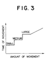
- the method has been proposed of classifying the amount of movement into large, medium, and small movement and storing in advance in a ROM patterns of acceleration and deceleration with acceleration times and deceleration times suitable for each of the same, but the disadvantage remains in that this results in a massive required memory capacity and further unnatural characteristics of the amount of movement and movement time, so is not preferable in terms of control. Further, it was not possible to freely change the acceleration and deceleration by this technique.
- a numerical control method and system is proposed in EP-A-0 089 156, for control of the position of a robot arm by control of the frequency of driving pulses fed to a servo system.
- a normalised target function for the pulse frequency is stored in memory.
- the frequency of driving pulses fed to the servo system at the time of a commanded movement is equal to the product of the stored target function and the commanded amount of displacement, divided by the time spent in acceleration (or deceleration, the acceleration/deceleration characteristic being symmetrical). In this system too, the form of the acceleration and deceleration cannot be freely changed.
- GB-A-2 018 466 describes a numerical control system in which a triangular-type acceleration/deceleration characteristic is applied.
- EP-A-0 191 103 describes a numerical control method and apparatus for controlling the two connected portions of a hinged arm by outputting target velocity or position values to motors or decelerators located at the hinges.
- Normalized acceleration/deceleration characteristics are stored in memory together with data related to the load torque on the motors/decelerators when the robot arm is in particular positions.
- the stored load/torque data is used to determine the amount of time to be spent in acceleration (or deceleration) when exercising point-to-point control, or the amount of movement to be achieved during the acceleration/deceleration.
- a velocity or position command is issued based on the stored acceleration/deceleration characteristic and this calculated amount of time/movement.
- an object of the present invention is to enable free setting of the pattern of acceleration and deceleration free from the amount of movement or movement time with the assumption of realization of quick, smooth PTP operations.
- the numerical control method of the present invention lies in a numerical control method for controlling the value of a parameter, as it changes between a first value and a second value, in conformity with a target function defining how the value of the controlled parameter changes with time, characterised in that it comprises the following steps:
- the numerical control system of the present invention provides a numerical control system for controlling the value of a parameter, as it changes between a first value and a second value, in conformity with a target function defining how the value of the controlled parameter changes with time, characterised in that the system comprises:
- reference values Y ref of the physical-state representing amount are input.
- it is strongly demanded to quickly and smoothly move from a reference value Y ref1 to a reference value Y ref2 .
- a PTP (point to point) operation which does not dictate the path from reference point Y ref1 to the reference value Y ref2 is made use of in a wide range of fields such as robot control, temperature control, camera focus control, slide control of a CD player, video disk, and the like, and DC point control of electrical circuits.
- an algorithm has been constructed for enabling free and easy generation of new target functions, by introduction of a very small number of parameters, along with changes in the factors characterizing the target functions, i.e., (1) the pattern of acceleration and deceleration, (2) the amount of change, and (3) the changes in the acceleration time and deceleration time (including expansion and contraction of time axis).
- Y a (t) ⁇ a (T pa ) ⁇ a (T pa ) + ⁇ d (T pd ) • ⁇ Y t • ⁇ a • y a (t) 0 ⁇ t ⁇ T pa
- the acceleration time is given as T pa
- the deceleration time as T pd
- the total movement time as T t
- the amount of acceleration movement as ⁇ Y a
- the amount of deceleration movement as ⁇ Y d
- the total amount of movement ⁇ Y t and the peak speed as Y ⁇ p .
- Total movement time T t acceleration time T pa + deceleration time T pd
- Total amount of movement ⁇ Y t amount of acceleration movement ⁇ Y a + amount of deceleration movement ⁇ Y d
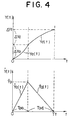
- Y(t) expresses the target function and the time differential dY(t)/dt of the target function expresses the target speed function.
- the relationship of the target value Y with respect to the time is shown at the top of Fig. 4, while the relationship of the target speed to the time is shown at the bottom of Fig. 4.
- the main factors characterizing a target function may be said to be (1) the pattern of acceleration and deceleration, (2) the amount of movement ⁇ Y t , and (3) the expansion and contraction of the time axis, such as the acceleration time T pa and the deceleration time T pd . Accordingly, the task given to the present invention is to construct an algorithm which enables free and easy production of a new target function by introduction of a very small number of parameters to deal with changes in such factors.
- y a (t) and y d (t) in equation (1) and equation (2) are dimension-less smooth continuous functions. These are referred to as normalized target functions.
- Equation (2) y d (t) is defined for 0 ⁇ t ⁇ T pd , but it is possible to change to deceleration by applying a reversal operation of the time axis. More specifically, it is possible to substitute T pd + Tp a - t in place of t in equation (2).
- ⁇ a and ⁇ d in equation (1) and equation (2) are dimension-less parameters and are introduced for the following two purposes.
- the first purpose is to give a degree of freedom to the selection of the normalized target function y(t). That is, when using the triangular pattern as shown in Fig. 4, the normalized target function y a (t) is introduced to enable absorption by the parameter ⁇ no matter if multiplied by t 2 /T p 2 , 10t 2 /T p 2 , or any other coefficient.
- the effect of the parameter ⁇ is not exhibited that much in the case of a simple function such as a triangular pattern, but a much more remarkable effect is obtained if a complicated function such as the later mentioned exponential (exp) type pattern is adopted.
- the second purpose of introduction of ⁇ is to establish a relationship between the normalized target function y(t) and the servo loop characteristic. That is, the normalized target function y(t) is an extremely important factor for a certain servo loop. By defining this relationship by ⁇ , use may be made of it when producing a target function.
- the parameter ⁇ means the length of the horizontal axis (time axis) of the rectangular shape of the height Y a (T pa )dot (shown by the dotted line in Fig. 7 which gives an area equal to the area ⁇ Y a surrounded by the acceleration (deceleration) curve as shown in Fig. 7. Note that this is expressed as a function of T p like ⁇ (T p ) because the value of ⁇ is dependent on T pa and T pd .
- the parameter ⁇ may be found in the following way:
- the total amount of movement ⁇ Y t and the total movement time T t are by nature determined by a large system including the servo system and the algorithm of the present invention does not have anything to do with the determination of the system.
- the movement time T t that is, T pa and T pd , is an important factor in the system and is determined by the magnitude of the load of the servo system and other physical situations, the capacities of the actuator and power system, etc. For example, as shown in Fig. 8, there are cases where it is determined as a function of ⁇ Y t :
- the speed Y ⁇ p of the peak point increases if the amount of movement ⁇ Y t increases.
- the target speed function grows as shown in Fig. 10 for example.
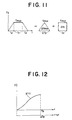
- the area enclosed by the speed curve and the time axis is the amount of movement ⁇ Y t , and the following stands: ⁇ Y t1 ⁇ ⁇ Y t2 ⁇ ⁇ Y t3 ⁇ ... ⁇ ⁇ Y t6
- ⁇ Y max ⁇ (T p ) • Y max
- the peak time T p was treated as a constant, but in the actual application, the peak time T p is changed in accordance with the amount of movement ⁇ Y t as shown in Fig. 8 and the min point and max point shown in Fig. 8 appear due to the presence of the f-characteristic of the servo loop or the motor maximum speed. Further, this application is easy even if the form of the acceleration and deceleration changes.
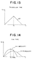
- the total movement time T t , the acceleration and deceleration times T pa and T pd etc. are determined by the situation and laws of the control system such as the actuator, load, and power system. Therefore, consideration is given to a method for producing a target function in accordance with the determined times, that is, producing a target function with respect to the expansion and contraction of the time axis.
- Fig. 12 The situation when multiplying the time axis by a when the normalized target function y(t) is given is shown in Fig. 12.
- the object in this case is to derive an equation in the case where the equation (18) and equation (19) of the target function is subjected to expansion or contraction of the time axis.
- This exp type acceleration and deceleration pattern is one of the optimal target functions considering the characteristic of a positional servo loop (so called "f-characteristic"). Further, this target function is a function which can be infinitely differentiated at all points, so has the advantage of not causing unnecessary vibration in the mechanical system. Further, calculation becomes easier if the servo loop is simulated by software.
- Y 0 ( s ) 1 (1 + T 1 s )(1 + T 2 s )(1 + T 3 s ) ⁇ • ⁇ Y t /2 s
- K K i M T 1 T 2 T 3
- K p K T 1 T 2 + T 2 T 3 + T 3
- T 1 K T 1 + T 2 + T 3
- T 2 and T 3 are the time constants in the third servo-loop.
- This target function is output to the step input of the servo loop shown in Fig. 15A, so is the maximum speed for the servo loop, Further, it is filtered, so it is considered the most suitable as the input.
- equation (41) is the same as the parameter ⁇ of equation (4) defined by the normalized target function as will be understood from a comparison of the forms of equation (44) and equation (45) and equation (18') and equation (19').
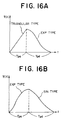
- the acceleration and deceleration pattern shown in Fig. 16A is an example of use of a triangular type acceleration pattern and an exp type deceleration pattern.
- the acceleration and deceleration pattern shown in Fig. 16B is an example of use of the exp type acceleration pattern and the sine type deceleration pattern.
- which kind of acceleration and deceleration pattern to use may be determined by the characteristics of the servo loop, the characteristics of the load of the actuator, etc., for example.
- Such an application can be expected to be of broad use in the control of various types of PTP (point to point) operations such as robot control, temperature control, camera focus control, slide control of a CD player, video disk, and the like, DC point control of electrical circuits, and the like.
- PTP point to point
Landscapes
- Engineering & Computer Science (AREA)
- Human Computer Interaction (AREA)
- Manufacturing & Machinery (AREA)
- Physics & Mathematics (AREA)
- General Physics & Mathematics (AREA)
- Automation & Control Theory (AREA)
- Numerical Control (AREA)
- Feedback Control In General (AREA)
- Control Of Position Or Direction (AREA)
- Developing Agents For Electrophotography (AREA)
Claims (4)
- Numerisches Steuerungsverfahren für die Steuerung des Werts eines Parameters (Y), während dieser sich zwischen einem ersten Referenzwert und einem zweiten Referenzwert ändert, nach Maßgabe einer Zielfunktion (Y(t)), die definiert, wie sich der Wert des gesteuerten Parameters (Y) zeitlich ändert,
gekennzeichnet durch die folgenden Verfahrensschritte:Eingeben eines Werts für die Differenz (ΔYt) zwischen dem ersten und dem zweiten Referenzwert des gesteuerten Parameters,Eingeben einer normierten Zielfunktion (y(t)), wobei diese normierte Zielfunktion (y(t)) eine Funktion ist, die ein gewünschtes Muster der zeitlichen Änderung des gesteuerten Parameters (Y) definiert und eine erste Funktion (ya(t)) umfaßt, die das gewünschte Änderungsmuster während einer Zeitperiode (Tpa) definiert, in der die Änderungsrate des gesteuerten Parameters (Y) großer wird, und eine zweite Funktion (yd(t)), die das gewünschte Änderungsmuster während einer Zeitperiode (Tpd) definiert, in der die Änderungsrate des gesteuerten Parameters (Y) kleiner wird,Berechnen von Korrekturwerten (β, δ) auf der Basis der eingegebenen Differenz (ΔYt) und der eingegebenen normierten Zielfunktion (y(t)) undBerechnen der Zielfunktion (Y(t)) aus der eingegebenen Differenz (ΔYt), der eingegebenen normierten Zielfunktion (y(t)) und den berechneten Korrekturwerten (β, δ), wobei die Zielfunktion (ya(t)) während der Zeitperiode, in der die Änderungsrate des gesteuerten Parameters (Y) größer wird, berechnet wird nach der Gleichung: - Numerisches Steuerungsverfahren nach Anspruch 1, bei dem βa = 1 und βd = 1, wenn die erste und die zweite Funktion der normierten Zielfunktion Dreieckkurven sind.
- Numerisches Steuerungssytem für die Steuerung des Werts eines Parameters (Y), während dieser sich zwischen einem ersten Referenzwert und einem zweiten Referenzwert ändert, nach Maßgabe einer Zielfunktion (Y(t)), die definiert, wie sich der Wert des gesteuerten Parameters (Y) zeitlich ändert,
dadurch gekennzeichnet, daß das System aufweist:eine Eingabeeinheit, die als Eingangssignal den Wert der Differenz (ΔYt) zwischen dem ersten und dem zweiten Referenzwert des gesteuerten Parameters und eine normierte Zielfunktion (y(t)) aufnimmt, wobei diese normierten Zielfunktion (y(t)) eine Funktion ist, die ein gewünschtes Muster der zeitlichen Änderung des gesteuerten Parameters (Y) definiert und eine erste Funktion (ya(t)) umfaßt, die das gewünschte Änderungsmuster während einer Zeitperiode (Tpa) definiert, in der die Änderungsrate des gesteuerten Parameters (Y) größer wird, und eine zweite Funktion (yd(t)), die das gewünschte Änderungsmuster während einer Zeitperiode (Tpd) definiert, in der die Änderungsrate des gesteuerten Parameters (Y) kleiner wird, wobei die erste und die zweite Funktion (ya(t), yd(t)) jeweils eine dimensionslose, glatte kontinuierliche Funktion darstellen,eine Korrekturwert-Berechnungseinheit, die Korrekturwerte (β, δ) auf der Basis der genannten Differenz (ΔYt) und der normierten Zielfunktion (y(t)) berechnet undeine Zielfunktions-Berechnungseinheit, die die Zielfunktion (Y(t)) auf der Basis der eingegebenen normierten Zielfunktion (y(t)), des eingegebenen Werts für die Differenz (ΔYt) zwischen dem ersten und dem zweiten Wert des gesteuerten Parameters und der berechneten Korrekturwerte (β, δ) berechnet, wobei die Zielfunktions-Berechnungseinheit so ausgebildet ist, daß sie den Wert der Zielfunktion (ya(t)), die während der Zeitperiode anzuwenden ist, in der die Änderungsrate des gesteuerten Parameters größer wird, nach der Gleichung: - Numerisches Steuerungssystem nach Anspruch 3, bei dem βa = 1 und βd = 1, wenn die erste und die zweite Funktion der normierten Zielfunktion Dreieckkurven sind.
Applications Claiming Priority (3)
| Application Number | Priority Date | Filing Date | Title |
|---|---|---|---|
| JP23025293 | 1993-09-16 | ||
| JP23025293A JP3395278B2 (ja) | 1993-09-16 | 1993-09-16 | 数値制御方法と数値制御装置 |
| JP230252/93 | 1993-09-16 |
Publications (3)
| Publication Number | Publication Date |
|---|---|
| EP0644471A2 EP0644471A2 (de) | 1995-03-22 |
| EP0644471A3 EP0644471A3 (de) | 1995-11-15 |
| EP0644471B1 true EP0644471B1 (de) | 2000-03-29 |
Family
ID=16904902
Family Applications (1)
| Application Number | Title | Priority Date | Filing Date |
|---|---|---|---|
| EP94402067A Expired - Lifetime EP0644471B1 (de) | 1993-09-16 | 1994-09-16 | Verfahren und System zur numerischen Steuerung mit Sollwerteinstellung von Beschleunigung und Verzögerung |
Country Status (7)
| Country | Link |
|---|---|
| US (2) | US5675496A (de) |
| EP (1) | EP0644471B1 (de) |
| JP (1) | JP3395278B2 (de) |
| KR (1) | KR100310352B1 (de) |
| CA (1) | CA2132119A1 (de) |
| DE (1) | DE69423688T2 (de) |
| MY (1) | MY112404A (de) |
Families Citing this family (9)
| Publication number | Priority date | Publication date | Assignee | Title |
|---|---|---|---|---|
| JP3395278B2 (ja) * | 1993-09-16 | 2003-04-07 | ソニー株式会社 | 数値制御方法と数値制御装置 |
| US5911125A (en) * | 1995-08-23 | 1999-06-08 | Fanuc, Ltd. | CNC acceleration-deceleration control apparatus and method |
| US5804779A (en) * | 1996-11-21 | 1998-09-08 | Otis Elevator Company | Method for generating and scaling velocity profiles for elevator car doors |
| JP4660012B2 (ja) * | 2001-05-21 | 2011-03-30 | 東芝機械株式会社 | 数値制御装置 |
| WO2004095520A2 (en) * | 2003-04-22 | 2004-11-04 | Berkeley Process Control, Inc. | System of path planning for robotic manipulators based on maximum acceleration and finite jerk constraints |
| DE102009004572B4 (de) * | 2009-01-14 | 2010-08-19 | Abb Technology Ag | Verfahren und elektronische Einrichtung zur Kompensation des Driftverhaltens bei einem pneumatischen Stellglied während des Betriebs |
| JP5241919B2 (ja) | 2009-04-28 | 2013-07-17 | 三菱電機株式会社 | 指令生成装置 |
| KR101749515B1 (ko) * | 2010-10-27 | 2017-06-21 | 삼성전자 주식회사 | 모터 속도 제어 장치 및 그 방법 |
| ES1138872Y (es) | 2014-12-30 | 2015-07-28 | Ultrasion Sl | Dispositivo de desgasificación de caldos de aleacionese ligeras mediante ultrasonidos |
Family Cites Families (12)
| Publication number | Priority date | Publication date | Assignee | Title |
|---|---|---|---|---|
| US3979653A (en) * | 1973-09-27 | 1976-09-07 | Hymie Cutler | Velocity-change control system and method for numerical control machines |
| US3952238A (en) * | 1973-11-29 | 1976-04-20 | Hymie Cutler | Programmable positioning apparatus and acceleration control system particularly useful therein |
| NL7506457A (nl) * | 1974-06-06 | 1975-12-09 | Hoechst Ag | Werkwijze voor het bereiden van dicyaan. |
| JPS54123673A (en) * | 1978-03-16 | 1979-09-26 | Fanuc Ltd | Positioning control system |
| JPS58154009A (ja) * | 1982-03-08 | 1983-09-13 | Fanuc Ltd | 加減速制御方式 |
| US4491776A (en) * | 1982-05-25 | 1985-01-01 | Manhattan Engineering Company, Inc. | Servo operated digital positioning control system |
| JPS58211211A (ja) * | 1982-06-01 | 1983-12-08 | Fanuc Ltd | 数値制御方式 |
| JPH0799486B2 (ja) * | 1984-04-27 | 1995-10-25 | 松下電器産業株式会社 | 角加速度制御方法 |
| JPS63182715A (ja) * | 1987-01-23 | 1988-07-28 | Omron Tateisi Electronics Co | 位置決め制御装置 |
| EP0333870B1 (de) * | 1987-09-11 | 1994-11-30 | Kabushiki Kaisha Yaskawa Denki Seisakusho | Regelungssystem, das am besten einem periodischen sollwert folgt |
| KR0160998B1 (ko) * | 1992-09-18 | 1998-12-15 | 윤종용 | 로보트의 구동경로 계획방법 |
| JP3395278B2 (ja) * | 1993-09-16 | 2003-04-07 | ソニー株式会社 | 数値制御方法と数値制御装置 |
-
1993
- 1993-09-16 JP JP23025293A patent/JP3395278B2/ja not_active Expired - Fee Related
-
1994
- 1994-09-12 KR KR1019940022926A patent/KR100310352B1/ko not_active Expired - Fee Related
- 1994-09-13 MY MYPI94002412A patent/MY112404A/en unknown
- 1994-09-14 US US08/305,609 patent/US5675496A/en not_active Expired - Lifetime
- 1994-09-15 CA CA002132119A patent/CA2132119A1/en not_active Abandoned
- 1994-09-16 EP EP94402067A patent/EP0644471B1/de not_active Expired - Lifetime
- 1994-09-16 DE DE69423688T patent/DE69423688T2/de not_active Expired - Fee Related
-
1997
- 1997-01-23 US US08/792,851 patent/US5910893A/en not_active Expired - Lifetime
Also Published As
| Publication number | Publication date |
|---|---|
| EP0644471A3 (de) | 1995-11-15 |
| MY112404A (en) | 2001-06-30 |
| DE69423688T2 (de) | 2000-11-09 |
| JP3395278B2 (ja) | 2003-04-07 |
| DE69423688D1 (de) | 2000-05-04 |
| US5675496A (en) | 1997-10-07 |
| JPH0784626A (ja) | 1995-03-31 |
| EP0644471A2 (de) | 1995-03-22 |
| KR950009387A (ko) | 1995-04-21 |
| KR100310352B1 (ko) | 2001-12-15 |
| US5910893A (en) | 1999-06-08 |
| CA2132119A1 (en) | 1995-03-17 |
Similar Documents
| Publication | Publication Date | Title |
|---|---|---|
| Yi et al. | Two-degree-of-freedom control with robust feedback control for hard disk servo systems | |
| EP1102139B1 (de) | Vorrichtung und Verfahren zur Erzeugung glatter Kurven in einem Bewegungssteuerungssystem | |
| JP3904993B2 (ja) | 曲線補間方法 | |
| US5892345A (en) | Motion control for quality in jet cutting | |
| US5726896A (en) | Method and system for spline interpolation, and their use in CNC | |
| Liu et al. | Adaptive interpolation scheme for NURBS curves with the integration of machining dynamics | |
| Lin et al. | Development of a dynamics-based NURBS interpolator with real-time look-ahead algorithm | |
| US5151639A (en) | System for positioning a transducer | |
| US5988850A (en) | Curve interpolation method for performing velocity control during connecting motion of a robot | |
| EP0644471A2 (de) | Verfahren und System zur numerischen Steuerung mit Sollwerteinstellung von Beschleunigung und Verzögerung | |
| US5229896A (en) | Disk drive and method of controlling the same | |
| EP1398681A2 (de) | Vorrichtung und Verfahren zur Erzeugung glatter Kurven in einem Bewegungssteuerungssystem | |
| Red | A dynamic optimal trajectory generator for Cartesian Path following | |
| Van Aken et al. | On-line robot trajectory control in joint coordinates by means of imposed acceleration profiles | |
| US6163730A (en) | Method and control system for changing the state of a plant | |
| US6029095A (en) | Method and device for dynamic system control | |
| Li et al. | An adaptive off-line NURBS interpolator for CNC machining | |
| KR19990057121A (ko) | 컴퓨터 수치 제어 장치의 2차원 평면상의 실시간 윤곽 오차모델링 방법 | |
| KR100307202B1 (ko) | 신경망을이용한이송속도제어방법 | |
| Vazquez G et al. | Auto guided vehicle control using expanded time b-splines | |
| JPH07200031A (ja) | 数値制御方法と数値制御装置 | |
| Cpałka | Case study: interpretability of fuzzy systems applied to nonlinear modelling and control | |
| JPH08179833A (ja) | 位置決め制御装置の目標軌道に対する速度および加速度 の制限方法 | |
| JP3513989B2 (ja) | 位置決め制御系の指令補間方法 | |
| JP3303431B2 (ja) | 数値制御方法および数値制御装置 |
Legal Events
| Date | Code | Title | Description |
|---|---|---|---|
| PUAI | Public reference made under article 153(3) epc to a published international application that has entered the european phase |
Free format text: ORIGINAL CODE: 0009012 |
|
| AK | Designated contracting states |
Kind code of ref document: A2 Designated state(s): DE FR GB SE |
|
| PUAL | Search report despatched |
Free format text: ORIGINAL CODE: 0009013 |
|
| AK | Designated contracting states |
Kind code of ref document: A3 Designated state(s): DE FR GB SE |
|
| 17P | Request for examination filed |
Effective date: 19960416 |
|
| 17Q | First examination report despatched |
Effective date: 19980414 |
|
| GRAG | Despatch of communication of intention to grant |
Free format text: ORIGINAL CODE: EPIDOS AGRA |
|
| GRAG | Despatch of communication of intention to grant |
Free format text: ORIGINAL CODE: EPIDOS AGRA |
|
| GRAH | Despatch of communication of intention to grant a patent |
Free format text: ORIGINAL CODE: EPIDOS IGRA |
|
| GRAH | Despatch of communication of intention to grant a patent |
Free format text: ORIGINAL CODE: EPIDOS IGRA |
|
| GRAA | (expected) grant |
Free format text: ORIGINAL CODE: 0009210 |
|
| AK | Designated contracting states |
Kind code of ref document: B1 Designated state(s): DE FR GB SE |
|
| REF | Corresponds to: |
Ref document number: 69423688 Country of ref document: DE Date of ref document: 20000504 |
|
| ET | Fr: translation filed | ||
| PLBE | No opposition filed within time limit |
Free format text: ORIGINAL CODE: 0009261 |
|
| STAA | Information on the status of an ep patent application or granted ep patent |
Free format text: STATUS: NO OPPOSITION FILED WITHIN TIME LIMIT |
|
| 26N | No opposition filed | ||
| REG | Reference to a national code |
Ref country code: GB Ref legal event code: IF02 |
|
| PGFP | Annual fee paid to national office [announced via postgrant information from national office to epo] |
Ref country code: SE Payment date: 20030904 Year of fee payment: 10 |
|
| PG25 | Lapsed in a contracting state [announced via postgrant information from national office to epo] |
Ref country code: SE Free format text: LAPSE BECAUSE OF NON-PAYMENT OF DUE FEES Effective date: 20040917 |
|
| EUG | Se: european patent has lapsed | ||
| PGFP | Annual fee paid to national office [announced via postgrant information from national office to epo] |
Ref country code: FR Payment date: 20080915 Year of fee payment: 15 |
|
| PGFP | Annual fee paid to national office [announced via postgrant information from national office to epo] |
Ref country code: GB Payment date: 20080917 Year of fee payment: 15 |
|
| PGFP | Annual fee paid to national office [announced via postgrant information from national office to epo] |
Ref country code: DE Payment date: 20081002 Year of fee payment: 15 |
|
| GBPC | Gb: european patent ceased through non-payment of renewal fee |
Effective date: 20090916 |
|
| REG | Reference to a national code |
Ref country code: FR Ref legal event code: ST Effective date: 20100531 |
|
| PG25 | Lapsed in a contracting state [announced via postgrant information from national office to epo] |
Ref country code: FR Free format text: LAPSE BECAUSE OF NON-PAYMENT OF DUE FEES Effective date: 20090930 Ref country code: DE Free format text: LAPSE BECAUSE OF NON-PAYMENT OF DUE FEES Effective date: 20100401 |
|
| PG25 | Lapsed in a contracting state [announced via postgrant information from national office to epo] |
Ref country code: GB Free format text: LAPSE BECAUSE OF NON-PAYMENT OF DUE FEES Effective date: 20090916 |