EP0644624A2 - Appareil de connexion muni d'un mécanisme d'éjection pour cartes de circuits intégrés - Google Patents
Appareil de connexion muni d'un mécanisme d'éjection pour cartes de circuits intégrés Download PDFInfo
- Publication number
- EP0644624A2 EP0644624A2 EP94113996A EP94113996A EP0644624A2 EP 0644624 A2 EP0644624 A2 EP 0644624A2 EP 94113996 A EP94113996 A EP 94113996A EP 94113996 A EP94113996 A EP 94113996A EP 0644624 A2 EP0644624 A2 EP 0644624A2
- Authority
- EP
- European Patent Office
- Prior art keywords
- memory card
- eject
- housing
- connector
- leading face
- Prior art date
- Legal status (The legal status is an assumption and is not a legal conclusion. Google has not performed a legal analysis and makes no representation as to the accuracy of the status listed.)
- Withdrawn
Links
Images


Classifications
-
- H—ELECTRICITY
- H01—ELECTRIC ELEMENTS
- H01R—ELECTRICALLY-CONDUCTIVE CONNECTIONS; STRUCTURAL ASSOCIATIONS OF A PLURALITY OF MUTUALLY-INSULATED ELECTRICAL CONNECTING ELEMENTS; COUPLING DEVICES; CURRENT COLLECTORS
- H01R13/00—Details of coupling devices of the kinds covered by groups H01R12/70 or H01R24/00 - H01R33/00
- H01R13/62—Means for facilitating engagement or disengagement of coupling parts or for holding them in engagement
- H01R13/629—Additional means for facilitating engagement or disengagement of coupling parts, e.g. aligning or guiding means, levers, gas pressure electrical locking indicators, manufacturing tolerances
-
- G—PHYSICS
- G06—COMPUTING OR CALCULATING; COUNTING
- G06K—GRAPHICAL DATA READING; PRESENTATION OF DATA; RECORD CARRIERS; HANDLING RECORD CARRIERS
- G06K13/00—Conveying record carriers from one station to another, e.g. from stack to punching mechanism
- G06K13/02—Conveying record carriers from one station to another, e.g. from stack to punching mechanism the record carrier having longitudinal dimension comparable with transverse dimension, e.g. punched card
- G06K13/08—Feeding or discharging cards
- G06K13/0806—Feeding or discharging cards using an arrangement for ejection of an inserted card
-
- G—PHYSICS
- G06—COMPUTING OR CALCULATING; COUNTING
- G06K—GRAPHICAL DATA READING; PRESENTATION OF DATA; RECORD CARRIERS; HANDLING RECORD CARRIERS
- G06K13/00—Conveying record carriers from one station to another, e.g. from stack to punching mechanism
- G06K13/02—Conveying record carriers from one station to another, e.g. from stack to punching mechanism the record carrier having longitudinal dimension comparable with transverse dimension, e.g. punched card
- G06K13/08—Feeding or discharging cards
-
- H—ELECTRICITY
- H01—ELECTRIC ELEMENTS
- H01R—ELECTRICALLY-CONDUCTIVE CONNECTIONS; STRUCTURAL ASSOCIATIONS OF A PLURALITY OF MUTUALLY-INSULATED ELECTRICAL CONNECTING ELEMENTS; COUPLING DEVICES; CURRENT COLLECTORS
- H01R13/00—Details of coupling devices of the kinds covered by groups H01R12/70 or H01R24/00 - H01R33/00
- H01R13/62—Means for facilitating engagement or disengagement of coupling parts or for holding them in engagement
- H01R13/629—Additional means for facilitating engagement or disengagement of coupling parts, e.g. aligning or guiding means, levers, gas pressure electrical locking indicators, manufacturing tolerances
- H01R13/633—Additional means for facilitating engagement or disengagement of coupling parts, e.g. aligning or guiding means, levers, gas pressure electrical locking indicators, manufacturing tolerances for disengagement only
Definitions
- This invention generally relates to the art of electrical connectors and, particularly, to a connector apparatus having a header connector adapted for receiving a memory card or IC pack, with means for ejecting the IC pack therefrom.
- a conventional connector apparatus for an IC pack or memory card includes a generally U-shaped frame having a pair of guide grooves inside each of a pair of side frame portions, with a connector section joining or extending between the side frame portions.
- a planar IC pack or memory card, in a rectangular card package, is inserted into the apparatus between the side frame portions within the side guide grooves.
- a transverse array of socket terminals on a leading face of the IC pack electrically connect to an associated array of pin terminals on the connector section.
- Such connector apparatus often are provided with header connectors used for interconnecting semi-conductor or memory chips of the IC pack to a main electronic unit of a computer, for example.
- the header connector is used in conjunction with the IC pack or memory card for removably coupling the IC pack to a printed circuit board in the main electronic unit.
- the IC pack is inserted into the header connector and is extracted therefrom as needed.
- the extraction force of the IC pack i.e. the force between the respective terminal pins on the header connector and the respective socket terminals of the IC pack, is relatively high due to the tight fit required to obtain a good electrical interconnection between the terminals.
- These terminals typically are disposed at a high density which further increases the extraction forces.
- the card was grasped by a user and simply pulled out.
- a memory card or IC pack typically in the form of a relatively thin package, with the socket terminal array extending across substantially the entire leading face of the card, there is a relatively small area along the leading face of the card from which to eject the card.
- prior art ejecting mechanisms have consisted of complex multi-piece designs including springs, cams, sliders and trays, which are not only costly to inventory and assemble, but which often require special features on the memory card or IC pack itself to provide a surface or area from which to eject the card.
- PCMCIA Personal Computer Memory Card International Association
- ejecting mechanisms have been designed to accommodate such standard cards.
- these ejecting mechanisms have effected ejection of the card from a portion of the leading face outside the socket terminal array, on one or, more often, on both sides thereof.
- the mechanisms which push (or pull) a memory card straight away from the header connector usually require additional components, such as a tray, in order to engage both sides of the leading face of the card outside the socket terminal array and to effect a symmetrical and mechanically effective ejection.
- Other ejecting mechanisms such as the design disclosed in pending U.S. Patent Application Serial No. 08/082,652 and assigned to applicants' assignee, have been designed to eliminate the tray.
- these mechanisms have ejected the memory card from one outside corner of the leading face of the memory card and therefore provide an asymmetrical ejection which may, in some circumstances, provide relatively less leverage and a greater likelihood of damaging terminals as compared to ejecting mechanisms which utilize a generally symmetrical ejection.
- This invention is directed to providing a low profile, simplified and mechanically effective ejecting mechanism for an IC pack or memory card, which ejects the card along the leading face thereof inside an area defined by the socket terminal array and without the use of extraneous components typical of the prior art.
- An object, therefore, of the invention is to provide a new and improved ejector system for use with a connector apparatus for IC packs or memory cards.
- the ejector system includes a header connector into which an IC pack is inserted and from which it is ejected.
- the header connector includes a U-shaped housing with a plurality of pin terminals mounted in the bight portion thereof and having terminal mating portions which form a terminal array.
- the IC pack is a rectangular portable card of known configuration and includes a shell within which is mounted a circuit substrate with electronic components such as integrated circuits, memory chips or the like. Electrical contacts are coupled to the circuit substrate and communicate with a leading face of the memory card shell, forming a transverse contact array adapted to mate with the terminal array of the header connector.
- the header connector includes opposing side walls with a centerline therebetween generally coincident with a centerline of the IC pack and extending in the direction of insertion of the IC pack into the header connector.
- a unitary ejecting lever is pivotally mounted to the header connector, with a first end adapted to eject the IC pack from the header connector.
- An elongated push-rod is reciprocally mounted on one side of the header connector, with one end of the push-rod engageable with a second end of the ejecting lever for pivoting the lever in response to actuation of the push-rod.
- the invention contemplates that the first or ejecting end of the ejecting lever engage and eject the IC pack generally along the leading face thereof inside an area defined in the transverse or horizontal direction by the memory card contact array, and in the vertical direction by the height of the leading face.
- Complementary interengaging pivot means are provided between the ejecting lever and the header connector and are located between the ejecting end of the ejecting lever and one of the opposing side walls of the header connector. As disclosed herein, the interengaging pivot means are located intermediate opposite ends of the ejecting lever.
- the preferred embodiment of the connector apparatus includes the header connector, the ejecting lever, the push-rod, and a stamped and formed guide frame member for guiding the memory card between an inserted position and an ejected position.
- the ejecting end of the eject lever is adapted to engage the leading face of the memory card approximately along the centerline and below the contact array.
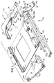
- the ejector system of the invention is embodied generally in a three-part ejector mechanism, generally designated 10.
- the mechanism is designed for incorporation directly in a connector apparatus which includes a header connector, generally designated 12, into which a memory card or IC pack 14 is inserted and from which it is ejected.
- ejector mechanism 10 includes: a first part in the form of a housing, generally designated 16, of header connector 12; a second part in the form of a one-piece ejecting lever, generally designated 18; and a third part in the form of a one-piece actuating push-rod, generally designated 20.
- a fourth part in the form of a guide frame, generally designated 22, is employed to facilitate guiding the insertion and extraction of memory card 14 and reciprocal movement of push-rod 20.
- the guide frame may include a plurality of mounting pegs 23 for insertion into appropriate holes in a substrate such as a printed circuit board and a grounding tab 25 for grounding the memory card to an underlying apparatus.
- guide frame 22 may be incorporated directly into header connector 12.
- guide frame 22 may extend in toward the header connector to form the floor of housing 16 or a portion thereof.
- header connector housing 16 and push-rod 20 are individually and integrally molded of dielectric material such as plastic or the like.
- Lever 18 and guide frame 22 may be molded of similar material, or stamped and formed of conductive sheet metal.
- no other extraneous components are required to assemble or to operate the ejector mechanism.
- header connector housing 16 is unitarily molded of plastic material and includes an elongated body portion 24 and two side wall portions 26 whereby the housing is generally U-shaped, as seen most clearly in Figures 1-4.
- Side wall portions 26 include inwardly directed channels 28 into which memory card 14 is inserted in the direction of arrow "A".
- Elongated body portion 24 is adapted for mounting a plurality of electrical terminals 30 in the form of pins having tail portions 30a ( Figures 3 and 6) for coupling, as by soldering, to appropriate circuit traces on a printed circuit board 29 ( Figure 6), by surface mounting or by soldering the tail portions within terminal-receiving holes (not shown).
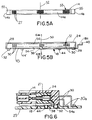
- the terminals 30 have terminal mating portions 30b disposed in two rows ( Figure 5B) and projecting from body portion 24 opposite the tail portions.
- the terminal mating portions of the pins are adapted to interconnect with corresponding contacts on memory card 14 when the card is properly inserted into header connector 12.
- the contacts on the card typically are in the form of receptacle terminals 27 disposed in two rows ( Figure 5A) in a leading face 14a of the card.
- housing 16 includes a bottom wall 45 having a pair of mounting pegs 32 extending downwardly therefrom for insertion into appropriate mounting holes in the printed circuit board.
- Actuating push-rod 20 includes a push button 20a at one end thereof and a drive end, generally designated 20b, at the opposite end thereof.
- the drive end forms part of a complementary interengaging drive means between the push-rod and ejecting lever 18, as will be seen below.
- the push-rod is positioned within channels 34 formed integrally with and projecting outwardly from one side of guide frame 22.
- a first side channel 33 may be integrally formed on an inside, or card facing side, of actuating push-rod 20.
- Push button 20a of the push-rod is exposed at the front of the guide frame, as seen in Figure 2, and the drive end 20b of the push-rod projects out of the rear-most channel 34 for complementary interengagement with ejecting lever 18.
- the push-rod is reciprocally mounted for movement in the direction of double-headed arrow "B" (Figs. 1 and 2).
- the push-rod is manually manipulatable by a user pushing on push button 20a in the direction of arrow "C” (Fig. 2).
- ejecting lever 18 is elongated and includes a lever arm 36 having an ejecting tab 38 at one end and an offset drive tab 40 at the opposite end.
- the drive tab cooperates with drive end 20b of push rod 20, as described hereinafter.
- a pivot hole 42 is formed in arm 36 of ejecting lever 18 between its ends, i.e. between ejecting tab 38 and drive tab 40.
- Pivot hole 42 embraces a pivot boss 44 on the underside or bottom wall 45 of housing 16 of header connector 12 whereby the ejecting lever is rotatable about the boss in the direction of arrow "D".
- pivot hole 42 and pivot boss 44 define complementary interengaging pivot means between the ejecting lever and the header connector.
- a second pivot boss 44' projects from the bottom wall of the header connector housing on an opposite side thereof. This additional pivot boss is provided so that the header connector can be used with ejecting lever 18 and push-rod 20 at the opposite side of the header connector.
- complementary interengaging drive means are provided between ejecting lever 18 and push-rod 20 for effecting actuation or pivoting of the lever in response to actuating or manually pushing on push button 20a of the push-rod in the direction of arrow "C" (Fig. 2). More particularly, drive end 20b of the push-rod is bifurcated to define a pair of axially extending arms 46a and 46b which, in turn, define a slot 48 therebetween. Drive tab 40 of ejecting lever 18 projects into slot 48, such that the drive tab engages a shoulder 46c when the push-rod is pushed in the direction of arrow "C".
- Arms 46a and 46b are in different planes, and drive tab 40 projects from an offset lip 18a of the ejecting lever. In this manner, arm 46a overlies the top of lever arm 36, whereas arm 46b extends below lip 18a, with drive tab 40 projecting into slot 48 between the arms. Lastly, arm 46b has a transverse flange 49 which will engage lip 18a to hold the push-rod in assembled condition, i.e. against removal of the push-rod from channels 34 opposite the direction of arrow "C".
- header connector 12 includes a plurality of pin terminals 30 mounted in body portion 24 of housing 16 to form a terminal array 51 (Fig. 5B) defined by rows of terminals extending in a transverse direction within the body portion of the housing, i.e. perpendicular to the direction of insertion of the memory card.
- the terminal array is adapted to mate with a corresponding contact array 53 (Fig. 5A) on the leading face 14a of the memory card 14.
- the header connector is further defined by a centerline 50 located midway between the two outer terminals on either side of the terminal array 51, i.e. intersecting the midpoint of each row of terminals.
- memory card or IC pack 14 includes a centerline 52 which is equidistant between the two outer contacts on either side of the contact array 53 and which intersects contact array 53 in the center thereof.
- centerlines 50 and 52 preferably are coincident.
- bottom wall 45 of elongated body portion 24 of header connector housing 16 has a triangular-shaped cutout 54 into which ejecting tab 38 of ejecting lever 18 projects.
- An apex 54a (Fig. 3) of the cutout may be located anywhere along the bottom wall 45, but in the preferred embodiment, it is positioned approximately along centerline 50 of the header connector.
- Ejecting tab 38 projects into an elongated receptacle 56 of body portion 24 into which edge 14a of memory card 14 is received.
- ejecting tab 38 engages a portion of the leading face 14a of the memory card inside an area defined horizontally by the outermost contacts of the contact array 53 and defined vertically by the height of the leading face 14a. This is seen most clearly in Figure 5A and 5B wherein the ejecting tab 38 engages the leading face 14a of the memory card at an area along the leading face within area D (Fig. 5A). In prior art memory card ejecting mechanisms, the eject lever or tray engages the leading face outside this area, typically on one or both of the outer corners 55 of the leading face.
- the ejecting tab 38 engages the leading face 14a of the memory card approximately along the centerline 52 thereof below the contact array 53, as shown in Figure 6. This provides for a relatively uniform and mechanically effective ejection of the memory card from the header connector and minimizes costs associated with extraneous components such as trays.
- memory card or IC pack 14 is inserted between a pair of side channels 60 and 33 of guide frame 22 and push-rod 20 respectively, in the direction of arrow "E" (Figs. 1 and 2).
- the memory card is inserted in the direction of arrow "A” and enters channels 28 of side wall portions 26 of header connector housing 16 until the leading face 14a of the memory card enters receptacle 56 of the header connector and the receptacle contacts 27 of contact array 53 are electrically coupled to the header pins 30 of terminal array 51.
- leading face 14a of the memory card will engage ejecting tab 38 of ejecting lever 18 and cause the lever to pivot and move push-rod 20 opposite the insertion direction to the ejecting condition shown in Figure 2.
- a user pushes on push button 20a of push-rod 20 in the direction of arrow "C” (Fig. 2).
- the push-rod rotates ejecting lever 18 in the direction of arrow “D” (Figs. 3 and 4) which causes ejecting tab 38 of the ejecting lever to move in the direction of arrows "F” to engage a portion of leading face 14a of memory card 14 and eject the memory card at least to the extent of disengaging receptacle terminals 27 from terminal pins 30, whereupon the memory card can be easily removed manually.
Landscapes
- Physics & Mathematics (AREA)
- General Physics & Mathematics (AREA)
- Engineering & Computer Science (AREA)
- Theoretical Computer Science (AREA)
- Coupling Device And Connection With Printed Circuit (AREA)
- Details Of Connecting Devices For Male And Female Coupling (AREA)
Applications Claiming Priority (2)
| Application Number | Priority Date | Filing Date | Title |
|---|---|---|---|
| US08/122,205 US5456610A (en) | 1993-09-16 | 1993-09-16 | Connector apparatus equipped with an ejector mechanism for IC packs |
| US122205 | 1993-09-16 |
Publications (2)
| Publication Number | Publication Date |
|---|---|
| EP0644624A2 true EP0644624A2 (fr) | 1995-03-22 |
| EP0644624A3 EP0644624A3 (fr) | 1996-07-31 |
Family
ID=22401315
Family Applications (1)
| Application Number | Title | Priority Date | Filing Date |
|---|---|---|---|
| EP94113996A Withdrawn EP0644624A3 (fr) | 1993-09-16 | 1994-09-07 | Appareil de connexion muni d'un mécanisme d'éjection pour cartes de circuits intégrés. |
Country Status (6)
| Country | Link |
|---|---|
| US (1) | US5456610A (fr) |
| EP (1) | EP0644624A3 (fr) |
| JP (1) | JP2897109B2 (fr) |
| KR (1) | KR0156023B1 (fr) |
| MY (1) | MY129997A (fr) |
| TW (1) | TW242188B (fr) |
Cited By (6)
| Publication number | Priority date | Publication date | Assignee | Title |
|---|---|---|---|---|
| WO1997010691A1 (fr) * | 1995-09-11 | 1997-03-20 | The Whitaker Corporation | Connecteur de carte memoire |
| EP0798813A3 (fr) * | 1996-03-29 | 1998-12-23 | Berg Electronics Manufacturing B.V. | Connecteur pour carte de mémoire d'une dimension transversale réduite |
| GB2330934A (en) * | 1997-10-31 | 1999-05-05 | Whitaker Corp | Ejector for a card reader |
| US5921792A (en) * | 1994-03-10 | 1999-07-13 | The Whitaker Corporation | Card connector and card-ejecting mechanism |
| US6036512A (en) * | 1997-06-30 | 2000-03-14 | The Whitaker Corporation | Electrical connector with card-ejection mechanism having two pivot points for easier ejection |
| DE10208481B4 (de) * | 2002-02-27 | 2005-09-08 | Siemens Ag | Station für elektronische Geräte |
Families Citing this family (22)
| Publication number | Priority date | Publication date | Assignee | Title |
|---|---|---|---|---|
| JP2847032B2 (ja) * | 1994-04-22 | 1999-01-13 | ヒロセ電機株式会社 | Icカード用電気コネクタ |
| JP3130784B2 (ja) * | 1995-12-28 | 2001-01-31 | アルプス電気株式会社 | 電子部品の端子構造 |
| TW390521U (en) * | 1997-06-05 | 2000-05-11 | Hon Hai Prec Ind Co Ltd | Electric connector |
| TW385084U (en) * | 1997-06-25 | 2000-03-11 | Hon Hai Prec Ind Co Ltd | IC card connectors |
| JP3273242B2 (ja) * | 1997-10-08 | 2002-04-08 | 日本航空電子工業株式会社 | カードコネクタ |
| TW360444U (en) * | 1997-10-20 | 1999-06-01 | Hon Hai Prec Ind Co Ltd | Card-withdrawing mechanism for electronic card connector |
| TW361718U (en) * | 1997-10-22 | 1999-06-11 | Hon Hai Prec Ind Co Ltd | Push lever structure for the electronic card connector |
| TW369224U (en) * | 1997-10-27 | 1999-09-01 | Hon Hai Prec Ind Co Ltd | Electronic card connector |
| US20070137653A1 (en) * | 2000-03-13 | 2007-06-21 | Wood Thomas J | Ventilation interface for sleep apnea therapy |
| TW477480U (en) * | 2000-06-03 | 2002-02-21 | Hon Hai Prec Ind Co Ltd | Electronic card connector |
| JP2002042964A (ja) | 2000-07-24 | 2002-02-08 | Molex Inc | カード用コネクタ |
| TW534397U (en) * | 2001-07-20 | 2003-05-21 | Hon Hai Prec Ind Co Ltd | Electronic card connector |
| JP3768125B2 (ja) * | 2001-08-10 | 2006-04-19 | 山一電機株式会社 | カードコネクタ |
| TW509395U (en) * | 2001-10-26 | 2002-11-01 | Hon Hai Prec Ind Co Ltd | Electronic card connector |
| US6824969B1 (en) | 2004-03-09 | 2004-11-30 | Hon Hai Precision Ind. Co., Ltd | Low profile electrical assembly |
| JP4054022B2 (ja) * | 2004-03-18 | 2008-02-27 | 山一電機株式会社 | Icカード用コネクタ |
| JP4200331B2 (ja) * | 2005-09-14 | 2008-12-24 | パナソニック電工株式会社 | メモリカード保持構造 |
| US7518880B1 (en) | 2006-02-08 | 2009-04-14 | Bi-Link | Shielding arrangement for electronic device |
| US7626826B2 (en) * | 2007-01-31 | 2009-12-01 | Sun Microsystems, Inc. | Expansion card carrier and method for assembling the same |
| US20100257732A1 (en) * | 2009-04-14 | 2010-10-14 | Ziberna Frank J | Shielding Arrangement for Electronic Device |
| US8177564B1 (en) | 2010-12-03 | 2012-05-15 | Yamaichi Electronics Co., Ltd. | Receptacle connector and an electrical connector using the same |
| US8767381B2 (en) | 2011-05-31 | 2014-07-01 | Apple Inc. | Systems and methods for ejecting removable modules from electronic devices |
Family Cites Families (10)
| Publication number | Priority date | Publication date | Assignee | Title |
|---|---|---|---|---|
| JPH0541511Y2 (fr) * | 1987-05-18 | 1993-10-20 | ||
| WO1989002167A1 (fr) * | 1987-08-28 | 1989-03-09 | Firma Trw Daut + Rietz Gmbh & Co. Kg | Dispositif de raccordement electrique |
| JPH0541509Y2 (fr) * | 1988-03-03 | 1993-10-20 | ||
| US5026296A (en) * | 1990-03-05 | 1991-06-25 | Japan Aviation Electronics Industry, Limited | Electrical connector equipped with release mechanism |
| JPH0737159Y2 (ja) * | 1990-04-26 | 1995-08-23 | ホシデン株式会社 | メモリカードコネクタ |
| JPH07120401B2 (ja) * | 1990-09-27 | 1995-12-20 | エスエムケイ株式会社 | イジェクト機構付きメモリカード用コネクタ |
| US5139435A (en) * | 1990-12-04 | 1992-08-18 | Hosiden Corporation | Multipolar electrical connector |
| US5197894A (en) * | 1991-05-30 | 1993-03-30 | Japan Aviation Electronics Industry, Limited | Electrical connector equipped with a release mechanism |
| EP0534138A1 (fr) * | 1991-08-23 | 1993-03-31 | Nippon Steel Corporation | Connecteur de carte à circuit intégré |
| US5149276A (en) * | 1991-12-18 | 1992-09-22 | Amp Incorporated | Modular holder having an ejector mechanism for a dual IC package |
-
1993
- 1993-09-16 US US08/122,205 patent/US5456610A/en not_active Expired - Fee Related
-
1994
- 1994-08-04 TW TW083107162A patent/TW242188B/zh active
- 1994-08-08 MY MYPI94002064A patent/MY129997A/en unknown
- 1994-09-07 EP EP94113996A patent/EP0644624A3/fr not_active Withdrawn
- 1994-09-14 JP JP6247253A patent/JP2897109B2/ja not_active Expired - Lifetime
- 1994-09-15 KR KR1019940023359A patent/KR0156023B1/ko not_active Expired - Fee Related
Cited By (7)
| Publication number | Priority date | Publication date | Assignee | Title |
|---|---|---|---|---|
| US5921792A (en) * | 1994-03-10 | 1999-07-13 | The Whitaker Corporation | Card connector and card-ejecting mechanism |
| WO1997010691A1 (fr) * | 1995-09-11 | 1997-03-20 | The Whitaker Corporation | Connecteur de carte memoire |
| US5967811A (en) * | 1995-09-11 | 1999-10-19 | The Whitaker Corporation | Memory card connector |
| EP0798813A3 (fr) * | 1996-03-29 | 1998-12-23 | Berg Electronics Manufacturing B.V. | Connecteur pour carte de mémoire d'une dimension transversale réduite |
| US6036512A (en) * | 1997-06-30 | 2000-03-14 | The Whitaker Corporation | Electrical connector with card-ejection mechanism having two pivot points for easier ejection |
| GB2330934A (en) * | 1997-10-31 | 1999-05-05 | Whitaker Corp | Ejector for a card reader |
| DE10208481B4 (de) * | 2002-02-27 | 2005-09-08 | Siemens Ag | Station für elektronische Geräte |
Also Published As
| Publication number | Publication date |
|---|---|
| JP2897109B2 (ja) | 1999-05-31 |
| TW242188B (en) | 1995-03-01 |
| MY129997A (en) | 2007-05-31 |
| KR950010183A (ko) | 1995-04-26 |
| EP0644624A3 (fr) | 1996-07-31 |
| JPH07106020A (ja) | 1995-04-21 |
| US5456610A (en) | 1995-10-10 |
| KR0156023B1 (ko) | 1998-11-16 |
Similar Documents
| Publication | Publication Date | Title |
|---|---|---|
| US5456610A (en) | Connector apparatus equipped with an ejector mechanism for IC packs | |
| EP0678824B1 (fr) | Mécanisme universel d'éjection pour un dispositif de connexion de carte à puce | |
| US5330363A (en) | IC pack connector apparatus with switch means | |
| EP0559017B1 (fr) | Connecteur de bord de carte avec mécanisme de verrouillage et éjection | |
| CA2042867C (fr) | Prise electrique a ejection | |
| US5511986A (en) | IC pack connector with detect switch | |
| EP0575832A1 (fr) | Moyens d'éjection pour un appareil de connexion de carte de circuits intégrés | |
| US20030073332A1 (en) | Card edge connector with improved ejector mechanism | |
| EP0908978A2 (fr) | Ensemble connecteur de carte | |
| US7238034B2 (en) | Memory card connector | |
| US7261578B2 (en) | Card connector | |
| US6361339B1 (en) | Electronic card connector having an integral ejector mechanism | |
| EP0547286A1 (fr) | Moyens d'éjection pour un appareil de connexion de carte de circuits ingégrés | |
| US7189088B2 (en) | Card connector with anti-mismating device | |
| US7090513B2 (en) | Electrical card connector | |
| US7311537B2 (en) | Card connector | |
| US5967812A (en) | Card ejector for card connector apparatus | |
| US7267565B2 (en) | Card connector with ejector | |
| US6702599B2 (en) | Card ejecting mechanism for an electronic card connector | |
| JP2002517834A (ja) | 自動的にスマートカードを排出する手段を備えたスマートカード接続用コネクタ | |
| US7247055B2 (en) | Card connector | |
| US7214098B2 (en) | Memory card connector | |
| US20020048980A1 (en) | Card connector equipped with means for preventing undesired card removal | |
| US7014118B1 (en) | Module header apparatus | |
| US20050176284A1 (en) | Card edge connector |
Legal Events
| Date | Code | Title | Description |
|---|---|---|---|
| PUAI | Public reference made under article 153(3) epc to a published international application that has entered the european phase |
Free format text: ORIGINAL CODE: 0009012 |
|
| AK | Designated contracting states |
Kind code of ref document: A2 Designated state(s): DE ES FR GB IT NL |
|
| PUAL | Search report despatched |
Free format text: ORIGINAL CODE: 0009013 |
|
| AK | Designated contracting states |
Kind code of ref document: A3 Designated state(s): DE ES FR GB IT NL |
|
| 17P | Request for examination filed |
Effective date: 19961213 |
|
| 17Q | First examination report despatched |
Effective date: 19990309 |
|
| GRAG | Despatch of communication of intention to grant |
Free format text: ORIGINAL CODE: EPIDOS AGRA |
|
| 17Q | First examination report despatched |
Effective date: 19990309 |
|
| GRAG | Despatch of communication of intention to grant |
Free format text: ORIGINAL CODE: EPIDOS AGRA |
|
| GRAH | Despatch of communication of intention to grant a patent |
Free format text: ORIGINAL CODE: EPIDOS IGRA |
|
| STAA | Information on the status of an ep patent application or granted ep patent |
Free format text: STATUS: THE APPLICATION IS DEEMED TO BE WITHDRAWN |
|
| 18D | Application deemed to be withdrawn |
Effective date: 20010206 |