EP0644732B1 - Modul-system zur realisierung von ringen, armbändern und anderem schmuck oder billigen schmuckstücken - Google Patents
Modul-system zur realisierung von ringen, armbändern und anderem schmuck oder billigen schmuckstücken Download PDFInfo
- Publication number
- EP0644732B1 EP0644732B1 EP94914552A EP94914552A EP0644732B1 EP 0644732 B1 EP0644732 B1 EP 0644732B1 EP 94914552 A EP94914552 A EP 94914552A EP 94914552 A EP94914552 A EP 94914552A EP 0644732 B1 EP0644732 B1 EP 0644732B1
- Authority
- EP
- European Patent Office
- Prior art keywords
- rings
- ring
- anular
- jewellery
- wedding
- Prior art date
- Legal status (The legal status is an assumption and is not a legal conclusion. Google has not performed a legal analysis and makes no representation as to the accuracy of the status listed.)
- Expired - Lifetime
Links
- 230000002093 peripheral effect Effects 0.000 claims description 7
- 230000000717 retained effect Effects 0.000 claims 2
- 229910052751 metal Inorganic materials 0.000 abstract description 21
- 239000002184 metal Substances 0.000 abstract description 21
- 238000003780 insertion Methods 0.000 abstract description 16
- 230000037431 insertion Effects 0.000 abstract description 16
- 150000002739 metals Chemical class 0.000 abstract description 7
- 238000005520 cutting process Methods 0.000 abstract description 3
- 238000009713 electroplating Methods 0.000 abstract description 3
- 238000005266 casting Methods 0.000 abstract 1
- 238000004519 manufacturing process Methods 0.000 abstract 1
- 238000007493 shaping process Methods 0.000 abstract 1
- 239000010437 gem Substances 0.000 description 15
- 238000000034 method Methods 0.000 description 15
- 230000008569 process Effects 0.000 description 15
- XEEYBQQBJWHFJM-UHFFFAOYSA-N Iron Chemical compound [Fe] XEEYBQQBJWHFJM-UHFFFAOYSA-N 0.000 description 12
- 230000008878 coupling Effects 0.000 description 10
- 238000010168 coupling process Methods 0.000 description 10
- 238000005859 coupling reaction Methods 0.000 description 10
- 239000003086 colorant Substances 0.000 description 9
- 230000000903 blocking effect Effects 0.000 description 6
- 229910052742 iron Inorganic materials 0.000 description 6
- 238000003466 welding Methods 0.000 description 6
- 229910001751 gemstone Inorganic materials 0.000 description 5
- 235000019640 taste Nutrition 0.000 description 5
- 238000004512 die casting Methods 0.000 description 4
- BASFCYQUMIYNBI-UHFFFAOYSA-N platinum Chemical compound [Pt] BASFCYQUMIYNBI-UHFFFAOYSA-N 0.000 description 4
- 239000007787 solid Substances 0.000 description 4
- 229910000832 white gold Inorganic materials 0.000 description 4
- 239000010938 white gold Substances 0.000 description 4
- 238000003723 Smelting Methods 0.000 description 3
- 238000005034 decoration Methods 0.000 description 3
- 239000010432 diamond Substances 0.000 description 3
- 229910003460 diamond Inorganic materials 0.000 description 3
- PCHJSUWPFVWCPO-UHFFFAOYSA-N gold Chemical compound [Au] PCHJSUWPFVWCPO-UHFFFAOYSA-N 0.000 description 3
- 239000010931 gold Substances 0.000 description 3
- 229910052737 gold Inorganic materials 0.000 description 3
- 229910001092 metal group alloy Inorganic materials 0.000 description 3
- BQCADISMDOOEFD-UHFFFAOYSA-N Silver Chemical compound [Ag] BQCADISMDOOEFD-UHFFFAOYSA-N 0.000 description 2
- 238000007792 addition Methods 0.000 description 2
- 239000000853 adhesive Substances 0.000 description 2
- 230000001070 adhesive effect Effects 0.000 description 2
- 239000000203 mixture Substances 0.000 description 2
- 229910052697 platinum Inorganic materials 0.000 description 2
- 239000010970 precious metal Substances 0.000 description 2
- 229910001112 rose gold Inorganic materials 0.000 description 2
- 229910052709 silver Inorganic materials 0.000 description 2
- 239000004332 silver Substances 0.000 description 2
- 210000002105 tongue Anatomy 0.000 description 2
- 241000826860 Trapezium Species 0.000 description 1
- 230000000295 complement effect Effects 0.000 description 1
- 238000010036 direct spinning Methods 0.000 description 1
- 238000000605 extraction Methods 0.000 description 1
- 239000011796 hollow space material Substances 0.000 description 1
- 230000002427 irreversible effect Effects 0.000 description 1
- 230000004048 modification Effects 0.000 description 1
- 238000012986 modification Methods 0.000 description 1
- 238000005498 polishing Methods 0.000 description 1
- 150000003839 salts Chemical class 0.000 description 1
- 238000009987 spinning Methods 0.000 description 1
Images


Classifications
-
- A—HUMAN NECESSITIES
- A44—HABERDASHERY; JEWELLERY
- A44C—PERSONAL ADORNMENTS, e.g. JEWELLERY; COINS
- A44C9/00—Finger-rings
- A44C9/0007—Finger-rings made of several rings
- A44C9/0015—Finger-rings made of several rings connected or interlinked to each other
- A44C9/003—Finger-rings made of several rings connected or interlinked to each other in a rotatable way
-
- A—HUMAN NECESSITIES
- A44—HABERDASHERY; JEWELLERY
- A44C—PERSONAL ADORNMENTS, e.g. JEWELLERY; COINS
- A44C27/00—Making jewellery or other personal adornments
Definitions
- the present invention concerns a modular system for the realization of jewellery or cheap jewelry articles like (wedding) rings, bracelets and other articles that may be changed in colour and in their external finish, with modular elements and/or with superposing layers.
- a modular form of jewellery is known for example from US-A-1,327,606.
- the value of the article is usually valued on the percentage of the precious metal and on the carats of the gems, while for more complete valuation also the working cost of the jewel should be considered. However, this cost can not be recovered, especially in case of smelting. Furthermore, a ring or any other jewel usually has a great loving value that gets completely lost with its selling or smelting.
- the aim of the present invention therefore is the one of responding to the following needs:
- the request may be solved to vary, according to the tastes and the occasions, the decorative elements of rings and other jewels, making use always of the same modular structure.
- the object of the present invention solves the problem of providing a jewellery article, in particular a wedding ring, that may be modified in its colour and in its external finish by providing a modular ring having the features as set forth in claim 1.
- Said covering blades bands or rings may be of different metal alloys and of different colours, or even coloured in different manners so as to define the different periods of marriage life.
- the blades may be added or removed. When they are added - and if the starting blades are cylindrical - they may be applied onto the ring, e.g., by means of spinning, while if the starting blades are plane they may be plastically deformed and welded to the opposite ends, or also fixed by means of two or more small disappearing screws to a wedding ring not provided with said blades.
- the present invention provides a process comprising the use of a tubular structure with a plurality of layers of different metals, obtained with the forced insertion of coaxial tubes one into the other, or by following wrapping up of metal sheeths, or by various deposits of electroplating performed in succession from which, by means of cuts with tools perpendicular to the axis of said composed tube, rings may be obtained with three-layer edges.
- the enclosed figures show a modular system for the realization of rings, bracelets and other articles of jewellery and cheap jewelry, in which the anular supporting element 1 of figure 1 has the cross-sectional shape of a solid with a semi-toroidal surface
- the supporting anular element 2 of figure 2 has the shape of a solid obtained by a semi-ellipse
- the supporting anular element 3 of figure 3 has the shape of a solid obtained by trapezium.
- the supporting anular element may have a section different from the ones shown, flat or with a different shape.
- the metal covering blades 1a, b, c, 2a, b, c and 3a, b, c are shaped upon the respective supporting elements by means of plastic deformation. Such deformation may take place by the direct spinning of a cylindrical blade onto the corresponding ring, i.e. curving a plane blade to the shape of a ring, whereby said blade is shaped with a transversal section corresponding to the one of the anular element, applied to the same and fixed to its free ends as shown in figure 4.
- the blade adhering to the supporting element and the superposed blades are united without adhesive means.
- the starting point may be a tubular element previously drawn to a plurality of layers; now the transversal turning with a hollow, diamond iron is performed which produces a ring with a corresponding half-round shape, or with a pointed diamond iron, which produces a ring with a mainly flat shape.
- a ring is obtained, in which on the lateral edges the colours and the thicknesses 4 of the drawn blades can be seen together with the supporting element, as shown in figure 5.
- One ore more metal covering blades may eventually show a surface with decorations.
- the number of the blades may usually vary from one to three, but conveniently they are two.
- the supporting anular element 4 is limited by a cylindrical internal suface 8 and by a cylindrical external surface 9.
- the external cylindrical surface 9 is provided at its sides with circumferential reliefs 10 and 11 for forming a central groove 12.
- the supporting anular element 4 is a part of the jewellery article : in its most immediate shape it might realize, for exemplifying but not limiting purposes, a part of a ring, i.e. of a jewel to wear at a finger. However, it might also be used for realizing ear-rings, broochs and other articles comprising a substantially anular part.
- the jewellery article can comprise at least one external additional anular element 5a, 5b, 5c, ... 5n, that modifies the aesthetic of the article.
- Each external additional anular element may be realized of the desired metal alloys, have the required external shapes by means of the desired working and finish. It must have an internal shape that allows at least a partial insertion into the central groove 12 of the supporting anular element 4 and a removable joint engagement with the same in correspondence with at leaast one of the circumferential reliefs 10 and 11. This is made possible by at least one corresponding groove obtained in the internal surface of the additional anular element 5a, 5b, 5c, .. 5n, shown in figures 6, 7, 8, 9, 10, 11, 12 and 13, in which the same or similar numbers show the same or similar elements.
- Figure 6 shows a jewellery article or, as it will be called for simplicity, a ring, in which at least the outer peripheral surface of the supporting anular element 4 is completely covered by only one additional anular element 5a.
- This additional element has an L-section and has two grooves 13a, 14a; the groove 13a may have a release insertion, due to the elasticity of the metal alloy of the additional anular element 5a, onto the circumferential relief 10, while the groove 14a will be over to the circumferential relief 11 after the release insertion.
- the external shape of the additional anular element 5a like the one of all elements described hereinbelow, may be different from the smooth and plane one shown in figure 6 and in the following figures.
- the supporting anular element 4 shown in figure 7 is only partially covered with an additional anular element 5b with a transversal L-section.
- this layer that covers only half the anular element might have an aesthetical function, however polished in the embodiment according to figure 8 where on the supporting anular element, an additional anular element 5b is provided with a release insertion, as well as an anular element 5c, which has the identical specular shape.
- the grooves 13b and 13c get inserted onto the corresponding circumferential reliefs 10 and 11 of the supporting anular element 4.
- the supporting anular element is partially covered by two additional anular elements 5d and 5e, on release insertion on their grooves 13d and 13e in the reliefs 10 and 11.
- the central groove space left free by the two additional, opposed anular elements 5d and 5e is occupied by ad additional anular element 6a with a polygonal section, without circumferential groove.
- the same space is occupied by a further additional anular element 6b with a circular section, also without circumferential groove.
- ad additional anular element 5f has a section comprising an external portion 15f with a decorating shape and finish, e.g. curved, and an internal portion 16f complementar to the shape of the central groove 12 of the supporting anular element 4 as well as to the reliefs 10 and 11 with the grooves 13f and 16f.
- the external additional anular element has - in this case - an open shape that is then curved as a ring for being coupled with the supporting anular element.
- the jewellery article comprises an external additional anular element 5g in the shape of a solid with a semi-toroidal surface, externally covered by two modelled covering metal blades 7 and internally provided with means that engage with the circumferential reliefs 10 and 11 in the central groove 12.
- the reliefs may eventually be elastic tongues provided on the circumference and that get inserted in the central groove 12 at ledge against the reliefs 10 and 11 of the supporting anular element 4, whereby said reliefs may form undercuts with the cylindrical surface of groove 12.
- grooves 13g and 14g of the additional anular element are defined by said elastic tongues and by the section side.
- the corresponding covering metal blade 7 is linked to the additional anular element 5g, for its external convering, without use of adhesive means and may be release by means of a cut.
- the anular article comprises a base body 4, or supporting element, provided at one end with an external threading 22. At the opposite end, the base body 4 has a circumferential relief 23.
- an external anular element 18 may be inserted as an element for the modification of aesthetics, said element being provided with a circumferential internal cavity 28 that covers, or at least enters into contact, with the relief 23 of the base body 4.
- the external anular element 18 may be held on the base body 4, that houses it by means of an internal threading 29 obtained in the end opposite to the circumferential cavity 28 or, if there is not internal threading 29, by means of a nut 17, externally smooth or appropriately shaped and internally threaded as shown in 27.
- the external threading 22 has an external diameter greater than the maximum one of the base body 4, if the circumferential relief 23 is excluded, so that between the base body 4 and the external anular element 18 after the assembling of the anular article a more or less wide cavity may exist.
- the same external surface 24 of the base body 4 might be finished or polished with different elements, like set gems or other elements not shown.
- the threaded coupling of the anular element 18 and of the nut 17 may be made perfect in a rigid blocking by means of a small blocking screw onto the base body 4 - not shown.
- Said threaded coupling may be part of a bayonet-joint shown in a scheme in figure 31, where a pawl 19 will get engaged, due to a partial rotation, in parts of threadings 23 on the base body 4.
- the anular element comprises a supporting base body 4 provided at each end with an external threading 22, having an external diameter equal to the external diameter of the base body 4.
- an external anular element 18 may be inserted with a sliding, more or less precise coupling, as modifying element of the external aesthetic of the article, that may be however finished and polished with set gems and other elements, not shown.
- the external anular element 18 may be hold by both ends on the housing base body 4, e.g. by means - according to the tastes or aesthetical choices - a first external finished nut 17 and a second nut 17 with at least one set gem 26.
- Figures 17, 18, 19 and 20 show, in dotted lines, modular elements 17 and 18 mounted onto the base body 4. The blocking of the nuts 17 onto the base body 4 takes place as above described.
- the anular article comprises a supporting base body 4 provided, at each end, with an external threading 22 with an external diameter greater that the external diameter of the base body 4.
- the threadings 22 of the base body 4 have the same direction while, of course, where there is one single nut 17 engaged by its own two threadings 27 with said two threadings 22, the latter ones may have different or opposite direction.
- the width of the nut 17 is equal to the transversal dimension of the base body 4.
- a third central threading may be provided between the lateral one 22 so as to engage the nuts 17, equal or, e.g. different, to those shown in figures 16, 19 and 20, onto base body 4.
- the anular element comprises a supporting base body 4 provided at each end with an external threading 22 having an external diameter equal to the one of base body 4.
- said base body 4 may be inserted, by screw coupling, two opposite nuts 17 that meet at ledge for covering the base body 4, while figure 24 shows the two nuts 17 in the shape of half-wedding-rings, assembled at distance so as to leave open part of the surface 24 of the base body 4.
- the nuts 17 may be however externally finished or polished with set gems or other elements, not shown.
- the threadings 22 of the base body 4 may be, in this case, of the same or of different direction.
- the anular article comprises the supporting base body 4 provided at both ends with an external threading 22, having an external diameter smaller or equal to the one of the base body 4.
- Said base body 4 has a plurality of transverse peripheral grooves 25.
- said grooves are shown as having a dovetail section, but of course they might be also T-shaped or having any other undercut.
- the grooves 25 have a length equal to the transversal dimension of the base body and cut the threadings 22, if these have equal diameter to the maximum external diameter of the base body 4.
- two nuts 17, threaded on their internal surface may be coupled with the external threadings of the base body 4.
- a plurality of laminar curve elements is provided, like e.g.
- a plurality of curve laminar elements 21, of a width smaller than the transversal dimensions of the base body 4 - e.g. submultiple of the same - may be transversally inserted into the same grooves 25 and may be lateraly blocked by means of threaded nuts 17.
- Said curve elements 20 and 21 may be smooth or finished on the surface, e.g. with reliefs or engravings of letters and numbers, of ideograms or similar, and have set gems or other, that may be combined according to tastes.
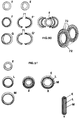
- a main feature of the system consists in that the presence of connection means between the pressure, joint, release, bayonet kind or the ones with grooved guides allows the direct coupling of two anular structures 36 without the need of the central module 1 for the realization of wedding rings or similar with different structures.
- connection means or connection means with grooved guides 37 provided at the centre of the external band of the central module 1, a means is provided for blocking the coupled parts and eventual means for the aesthetical covering of the uncovered guide.
- the means 34 for the release insertion provides the presence on the lateral edge of the central module 1 and/or on the peripheral structures 36, of one or more hooks 38 or similar that may be inserted into opposite openings 39 so as to get hooked, overcoming the resistance of springs 40 - said hooks may be removed and replaced by the extraction of the assemblying screws - to internal hooks 41 from which they may be unhooked, in case of detachment of the components, through openings 42 provided on the interal surface of module 1 and/or of the structures 36.
- a container 53 is shown with an internal threading 54 to be inserted by welding into any hole provided onto the central structure 1 or on the anular structures 36, for subsequently receiving by screwing the sector 55 with external grooves 56, containing the means for the release assemblage.
- the container 53 and the sector 55 may be of different shapes for being assembled with screws or in other ways as shown in figure 37, where the screws 56 may be applied through eyelets 57 of the ultraflat container 58.
- the coupling means consists of a plurality of access grooves 43, provided onto the module 1 until the central groove 37 so that when a tooth or similar, placed inside each anular structure 36 inserted in one of said grooves 43, reaches the central groove 37, following to the rotation of the parts, it may determine the blocking of the components be it for rings as well as for bracelets, for medals and eventual compositions of parts of wordings onto articles of jewellery and or cheap jewelry.
- the coupling system of the parts provides the insertion of small screws 46 into transversal passing through holes 47, provided in structures 36 and in the blind holes 48 onto central module 1.
- bracelets may be realized with small blocks carrying single letters that may be composed for obtaining a wording.
- necklaces may be realized in which the lock may be completely or partially replaced by means of male and female threadings.
- said necklaces with a replaceable lock may be connected with the release system.
- medals may be realized decorated with additional means, closed in a small pressure frame.
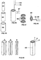
- the three-layer tube is obtained by the subsequent welding 69 of open blades or covers A-B-C of different metals and colours.
- An important variant of the process provides the deposit by electroplating, of subsequent metal layers onto single wedding rings or onto tubular structures to be cut, making use of solutions of the respective salts, with a final polishing, i.e. the electrolytical removal of the outer layers.
- the process described in figure 50 is a variant of the one described in figure 49 where, instead of the metal covers A-B-C, welded along edges 69, the wedding rings F and G are cut and opened into two parts F' and G', so as to be subsequently mounted and welded in 71 or in 72-73 around the central wedding ring E.
- a three-layer ring may be realized by means of the variant described in figure 51: said ring is obtained by the forced expansion of wedding rings E-L-M, of different diameters, that may be inserted one into the other.
- an already existing wedding ring may be covered with one or more layers of metals of different qualities and colours, by means of casts that allow the realization of two lateral small rings, each one of them covers half of the wedding ring, and these small rings are then united under pressure; on these rings, further layers of different metals may be superposed in succession, according to the purpose.
Landscapes
- Engineering & Computer Science (AREA)
- Manufacturing & Machinery (AREA)
- Adornments (AREA)
Claims (3)
- Module Ringe, Armbänder oder andere Juwelierartikel zur Versinnbildlichung von wichtigen Ereignissen im Leben eines Menschen, enthaltend einen inneren Ring (1, 2, 3), welcher ein erstes wichtiges Ereignis darstellt, einen zwischenliegenden Ring (1b, 2b, 3b), welcher ein zweites wichtiges Ereignis darstellt und wenigstens die äussere umlaufende Oberfläche des genannten inneren Ringes vollkommen umfasst und auf letzterem gehalten wird, einen äusseren Ring 1c, 2c, 3c), welcher ein drittes wichtiges Ereignis darstellt und wenigstens die äussere Oberfläche von beiden genannten inneren und zwischenliegenden Ringen vollkommen umfasst und auf dem genannten zwischenliegenden Ring gehalten wird, wobei die genannten inneren, zwischenliegenden und äusseren Ringe unterschiedlich voneinander sind.
- Module Ringe, Armbänder oder andere Juwelierartikel nach Patentanspruch 1, bei welchen der genannte zwischenliegende Ring aus zwei miteinander verbindbaren hohlen Halbringen gebildet ist, und der genannte äussere Ring aus zwei miteinander verbindbaren hohlen Halbringen gebildet ist, wobei jedes entsprechende Paar von Halbringen, wenn diese miteinander verbunden sind, einen vollständigen Kreis bilden.
- Module Ringe, Armbänder oder andere Juwelierartikel nach den Patentansprüchen 1 oder 2, bei welchen der genannte innere Ring einen vollständigen Kreis bildet und jeweils von den genannten zwischenliegenden und äusseren hohlen Halbringen umfasst wird.
Applications Claiming Priority (11)
| Application Number | Priority Date | Filing Date | Title |
|---|---|---|---|
| ITRM930224 | 1993-04-07 | ||
| IT93RM000224A ITRM930224A1 (it) | 1993-04-07 | 1993-04-07 | Anello, in particolare anello nuziale, modificabile nel colore e nella finitura esterna. |
| ITRM930223 | 1993-04-07 | ||
| IT93RM000223A ITRM930223A1 (it) | 1993-04-07 | 1993-04-07 | Articolo di oreficeria, in particolare un anello, modificabile in forma e colore. |
| ITRM930690 | 1993-10-13 | ||
| IT93RM000690A IT1266498B1 (it) | 1993-10-13 | 1993-10-13 | Articolo anulare di oreficeria o di bigiotteria, ad elementi componibili. |
| ITRM930772 | 1993-11-23 | ||
| IT93RM000773A ITRM930773A1 (it) | 1993-11-23 | 1993-11-23 | Sistema modulare componibile per anelli, bracciali e altri oggetti di oreficeria e di bigiotteria. |
| IT93RM000772A ITRM930772A1 (it) | 1993-11-23 | 1993-11-23 | Procedimento di costruzione di fedi, anelli e simili a tre strati sovrapposti di metalli di colori diversi. |
| ITRM930773 | 1993-11-23 | ||
| PCT/IT1994/000040 WO1994022341A1 (en) | 1993-04-07 | 1994-03-30 | A modular system for the realization of rings, bracelets and other jewellery or cheap jewelry articles |
Publications (2)
| Publication Number | Publication Date |
|---|---|
| EP0644732A1 EP0644732A1 (de) | 1995-03-29 |
| EP0644732B1 true EP0644732B1 (de) | 1998-05-13 |
Family
ID=27517901
Family Applications (1)
| Application Number | Title | Priority Date | Filing Date |
|---|---|---|---|
| EP94914552A Expired - Lifetime EP0644732B1 (de) | 1993-04-07 | 1994-03-30 | Modul-system zur realisierung von ringen, armbändern und anderem schmuck oder billigen schmuckstücken |
Country Status (7)
| Country | Link |
|---|---|
| US (1) | US5701765A (de) |
| EP (1) | EP0644732B1 (de) |
| AU (1) | AU687056B2 (de) |
| CA (1) | CA2135481A1 (de) |
| DE (1) | DE69410201T2 (de) |
| ES (1) | ES2118405T3 (de) |
| WO (1) | WO1994022341A1 (de) |
Cited By (1)
| Publication number | Priority date | Publication date | Assignee | Title |
|---|---|---|---|---|
| WO2026054287A1 (ko) * | 2024-09-09 | 2026-03-12 | 삼성전자주식회사 | 고정 부재를 포함하는 웨어러블 장치 |
Families Citing this family (18)
| Publication number | Priority date | Publication date | Assignee | Title |
|---|---|---|---|---|
| ES2076128B1 (es) * | 1994-02-21 | 1996-07-01 | Carlos Jimenez Joyeros S A | Anillo desmontable portador de piezas intercambiables, aplicable en joyeria y bisuteria. |
| DE737428T1 (de) * | 1995-04-11 | 1997-09-04 | Piaget International Sa | Schmuckring wie ein Fingerring oder Armband mit einem drehbaren äusseren Ringteil |
| IT1286175B1 (it) * | 1995-07-31 | 1998-07-07 | Claudio Christian Cerqua | Sistema di costruzione di prodotti di oreficeria e/o gioielleria, progettati in sezioni, settori e porzioni di settori, variamente |
| IT1315298B1 (it) * | 2000-03-21 | 2003-02-10 | Ezio Genero Srl | Anello a composizione variabile |
| EP1391161A1 (de) * | 2002-08-20 | 2004-02-25 | Cendres Et Metaux S.A. | Ring mit zwei gegeneinander verschiebbaren Teilen |
| AU2003231408A1 (en) * | 2003-05-02 | 2004-11-23 | Ken Hirata | Annular ornament |
| US7905111B2 (en) * | 2003-08-13 | 2011-03-15 | The Saltz Corporation | Bracelet |
| US20050097921A1 (en) * | 2003-11-12 | 2005-05-12 | Kuniya Maruyama | Copper colored jewelry and method of manufacturing copper colored jewelry |
| ITMI20061039A1 (it) | 2006-05-29 | 2007-11-30 | D-Effe S R L | Anello portachiavi apribile |
| WO2010148475A1 (en) * | 2009-06-24 | 2010-12-29 | Deanna Zavattin | Ornament, system including the ornament and arrangement and method |
| TR201001842A2 (tr) * | 2010-03-11 | 2010-08-23 | Mert Kuyumculuk Sanayi̇ Ve Ti̇caret Li̇mi̇ted Şi̇rketi̇ | Farkli montaj avantajlari sağlayan yüzük ve üretim metodu |
| CH704422A2 (fr) * | 2011-01-14 | 2012-07-31 | Renaud De Retz | Bijou modulaire. |
| US8931778B2 (en) * | 2013-03-15 | 2015-01-13 | Critsuccess Llc | Functional jewelry |
| EP3276433B1 (de) * | 2016-07-26 | 2019-05-15 | Omega SA | Untereinheit des gehäuses einer uhr, armbanduhr oder eines schmuckstücks |
| JP1593830S (de) * | 2017-05-31 | 2017-12-25 | ||
| JP1596238S (de) * | 2017-05-31 | 2021-01-25 | ||
| US11490698B2 (en) | 2017-06-02 | 2022-11-08 | Frederick Goldman, Inc. | Jewelry and methods of forming the same from multiple components |
| CN114828690A (zh) * | 2019-09-10 | 2022-07-29 | S 博克斯控股有限责任公司 | 可更换嵌体的珠宝 |
Family Cites Families (22)
| Publication number | Priority date | Publication date | Assignee | Title |
|---|---|---|---|---|
| DE25697C (de) * | J. MEGEMOND in Paris | Schutzhülsen für Fingerringe | ||
| US221728A (en) * | 1879-11-18 | Improvement in flnger-rlngs | ||
| US414956A (en) * | 1889-11-12 | Peters | ||
| GB189520155A (en) * | 1895-10-25 | 1896-06-20 | Walter James Carroll | A New or Improved Finger Ring Protector. |
| US1224193A (en) * | 1916-05-18 | 1917-05-01 | Milhening Inc J | Ring. |
| US1327606A (en) * | 1919-05-31 | 1920-01-13 | Bacharach Samuel | Finger-ring |
| FR518718A (fr) * | 1920-07-02 | 1921-05-30 | Henri Jean Marie Bourgeot | Bague alliance composée de deux anneaux de matières différentes |
| US1586606A (en) * | 1925-12-01 | 1926-06-01 | Ira L Cain | Finger ring |
| US1724130A (en) * | 1928-12-04 | 1929-08-13 | Henry M Dayton | Finger ring |
| US1999974A (en) * | 1935-02-14 | 1935-04-30 | Oscar Heyman & Brothers Inc | Wedding ring |
| US2128644A (en) * | 1937-06-16 | 1938-08-30 | Joseph W Gittler | Mourning band attachment for wedding rings |
| US2450762A (en) * | 1945-06-20 | 1948-10-05 | Clinton E Marshall | Ring |
| US2812604A (en) * | 1953-12-21 | 1957-11-12 | Melvin O Nelson | Calendar finger ring |
| CH612604A5 (de) * | 1976-05-31 | 1979-08-15 | Gori & Zucchi Spa | |
| US4226094A (en) * | 1978-06-07 | 1980-10-07 | Wolpoff Sharon A | Finger ring |
| GB8723231D0 (en) * | 1987-10-02 | 1987-11-04 | Byrne J R | Finger ring |
| FR2622415B1 (fr) * | 1987-10-30 | 1990-06-15 | Boucheron | Bijou a elements constitutifs interchangeables |
| FR2659000B1 (fr) * | 1990-03-02 | 1992-07-03 | Or Est | Bijoux circulaires comportant un anneau externe rotatif et procede de fabrication. |
| DE9016842U1 (de) * | 1990-12-13 | 1992-04-16 | Fa. Peter Heim, 7530 Pforzheim | Schmuckring, insbesondere Trauring |
| US5228316A (en) * | 1992-06-09 | 1993-07-20 | Meyrowitz Scott B | Ring with replaceable members |
| FR2693880B1 (fr) * | 1992-07-24 | 1994-10-07 | Pierre Voeltzel | Bijoux transformables. |
| IL103349A (en) * | 1992-10-05 | 1996-09-12 | Regev Eyal | Ring |
-
1994
- 1994-03-30 WO PCT/IT1994/000040 patent/WO1994022341A1/en not_active Ceased
- 1994-03-30 DE DE69410201T patent/DE69410201T2/de not_active Expired - Fee Related
- 1994-03-30 ES ES94914552T patent/ES2118405T3/es not_active Expired - Lifetime
- 1994-03-30 AU AU66886/94A patent/AU687056B2/en not_active Ceased
- 1994-03-30 US US08/331,587 patent/US5701765A/en not_active Expired - Fee Related
- 1994-03-30 CA CA002135481A patent/CA2135481A1/en not_active Abandoned
- 1994-03-30 EP EP94914552A patent/EP0644732B1/de not_active Expired - Lifetime
Cited By (1)
| Publication number | Priority date | Publication date | Assignee | Title |
|---|---|---|---|---|
| WO2026054287A1 (ko) * | 2024-09-09 | 2026-03-12 | 삼성전자주식회사 | 고정 부재를 포함하는 웨어러블 장치 |
Also Published As
| Publication number | Publication date |
|---|---|
| ES2118405T3 (es) | 1998-09-16 |
| US5701765A (en) | 1997-12-30 |
| EP0644732A1 (de) | 1995-03-29 |
| DE69410201D1 (de) | 1998-06-18 |
| DE69410201T2 (de) | 1998-12-03 |
| AU687056B2 (en) | 1998-02-19 |
| CA2135481A1 (en) | 1994-10-13 |
| AU6688694A (en) | 1994-10-24 |
| WO1994022341A1 (en) | 1994-10-13 |
Similar Documents
| Publication | Publication Date | Title |
|---|---|---|
| EP0644732B1 (de) | Modul-system zur realisierung von ringen, armbändern und anderem schmuck oder billigen schmuckstücken | |
| US8448464B2 (en) | Set of rings | |
| US2016679A (en) | Interlocking jewelry ornament | |
| US7357004B2 (en) | Flexible linkage for jewelry and method of making | |
| JPH06292608A (ja) | 装身具 | |
| US9360293B2 (en) | Contour band matching tool and methods | |
| KR101522907B1 (ko) | 호환사용이 가능하게 된 펜던트 액세서리 | |
| US20050005638A1 (en) | Multiple configuration ring | |
| CN216932134U (zh) | 可拆组可调宽窄的双螺旋结构珠宝首饰 | |
| CN217609838U (zh) | 可调宽窄和佩戴尺寸的珠宝首饰 | |
| CN210841801U (zh) | 可旋转吊坠 | |
| CN223247728U (zh) | 一种带碎碎金视觉效果的手镯 | |
| JP3097278U (ja) | 装飾具 | |
| CN223489278U (zh) | 一种环石圆珠链 | |
| CN111802759A (zh) | 手镯的定制加工方法及手镯 | |
| EP3133952B1 (de) | Verfahren zur herstellung einer verzierung aus edelmetall und daraus hergestelltes ornament | |
| CN213882036U (zh) | 一种套嵌型珠宝及其链状首饰品 | |
| CN217390134U (zh) | 一款为自己提供设计空间和个性创作的珠宝首饰 | |
| KR101657456B1 (ko) | 이종 또는 동종 재질의 장신구용 연결구의 제조방법 | |
| CN211747424U (zh) | 一种戒指 | |
| KR200420655Y1 (ko) | 장신구부재 | |
| KR200179934Y1 (ko) | 장신구 | |
| JP3049281U (ja) | 覆輪や石座が交換できる装飾用品 | |
| JP3081056U (ja) | 装飾具 | |
| JP3083543U (ja) | 装身具 |
Legal Events
| Date | Code | Title | Description |
|---|---|---|---|
| PUAI | Public reference made under article 153(3) epc to a published international application that has entered the european phase |
Free format text: ORIGINAL CODE: 0009012 |
|
| AK | Designated contracting states |
Kind code of ref document: A1 Designated state(s): DE ES FR GB NL |
|
| 17P | Request for examination filed |
Effective date: 19950405 |
|
| 17Q | First examination report despatched |
Effective date: 19960930 |
|
| GRAG | Despatch of communication of intention to grant |
Free format text: ORIGINAL CODE: EPIDOS AGRA |
|
| GRAG | Despatch of communication of intention to grant |
Free format text: ORIGINAL CODE: EPIDOS AGRA |
|
| GRAH | Despatch of communication of intention to grant a patent |
Free format text: ORIGINAL CODE: EPIDOS IGRA |
|
| GRAH | Despatch of communication of intention to grant a patent |
Free format text: ORIGINAL CODE: EPIDOS IGRA |
|
| GRAA | (expected) grant |
Free format text: ORIGINAL CODE: 0009210 |
|
| AK | Designated contracting states |
Kind code of ref document: B1 Designated state(s): DE ES FR GB NL |
|
| REF | Corresponds to: |
Ref document number: 69410201 Country of ref document: DE Date of ref document: 19980618 |
|
| REG | Reference to a national code |
Ref country code: ES Ref legal event code: FG2A Ref document number: 2118405 Country of ref document: ES Kind code of ref document: T3 |
|
| ET | Fr: translation filed | ||
| PLBE | No opposition filed within time limit |
Free format text: ORIGINAL CODE: 0009261 |
|
| STAA | Information on the status of an ep patent application or granted ep patent |
Free format text: STATUS: NO OPPOSITION FILED WITHIN TIME LIMIT |
|
| PGFP | Annual fee paid to national office [announced via postgrant information from national office to epo] |
Ref country code: NL Payment date: 19990329 Year of fee payment: 6 |
|
| 26N | No opposition filed | ||
| PG25 | Lapsed in a contracting state [announced via postgrant information from national office to epo] |
Ref country code: NL Free format text: LAPSE BECAUSE OF NON-PAYMENT OF DUE FEES Effective date: 20001001 |
|
| NLV4 | Nl: lapsed or anulled due to non-payment of the annual fee |
Effective date: 20001001 |
|
| PGFP | Annual fee paid to national office [announced via postgrant information from national office to epo] |
Ref country code: DE Payment date: 20010330 Year of fee payment: 8 |
|
| REG | Reference to a national code |
Ref country code: GB Ref legal event code: IF02 |
|
| PGFP | Annual fee paid to national office [announced via postgrant information from national office to epo] |
Ref country code: GB Payment date: 20020404 Year of fee payment: 9 |
|
| PG25 | Lapsed in a contracting state [announced via postgrant information from national office to epo] |
Ref country code: DE Free format text: LAPSE BECAUSE OF NON-PAYMENT OF DUE FEES Effective date: 20021001 |
|
| PG25 | Lapsed in a contracting state [announced via postgrant information from national office to epo] |
Ref country code: GB Free format text: LAPSE BECAUSE OF NON-PAYMENT OF DUE FEES Effective date: 20030330 |
|
| PGFP | Annual fee paid to national office [announced via postgrant information from national office to epo] |
Ref country code: FR Payment date: 20030408 Year of fee payment: 10 |
|
| PGFP | Annual fee paid to national office [announced via postgrant information from national office to epo] |
Ref country code: ES Payment date: 20030429 Year of fee payment: 10 |
|
| GBPC | Gb: european patent ceased through non-payment of renewal fee |
Effective date: 20030330 |
|
| PG25 | Lapsed in a contracting state [announced via postgrant information from national office to epo] |
Ref country code: ES Free format text: LAPSE BECAUSE OF NON-PAYMENT OF DUE FEES Effective date: 20040331 |
|
| PG25 | Lapsed in a contracting state [announced via postgrant information from national office to epo] |
Ref country code: FR Free format text: LAPSE BECAUSE OF NON-PAYMENT OF DUE FEES Effective date: 20041130 |
|
| REG | Reference to a national code |
Ref country code: FR Ref legal event code: ST |
|
| REG | Reference to a national code |
Ref country code: ES Ref legal event code: FD2A Effective date: 20040331 |