EP0645100A1 - Chaussure de sport - Google Patents
Chaussure de sport Download PDFInfo
- Publication number
- EP0645100A1 EP0645100A1 EP94113727A EP94113727A EP0645100A1 EP 0645100 A1 EP0645100 A1 EP 0645100A1 EP 94113727 A EP94113727 A EP 94113727A EP 94113727 A EP94113727 A EP 94113727A EP 0645100 A1 EP0645100 A1 EP 0645100A1
- Authority
- EP
- European Patent Office
- Prior art keywords
- shoe
- pressure distribution
- attached
- distribution plate
- distribution plates
- Prior art date
- Legal status (The legal status is an assumption and is not a legal conclusion. Google has not performed a legal analysis and makes no representation as to the accuracy of the status listed.)
- Granted
Links
Images


Classifications
-
- A—HUMAN NECESSITIES
- A43—FOOTWEAR
- A43B—CHARACTERISTIC FEATURES OF FOOTWEAR; PARTS OF FOOTWEAR
- A43B5/00—Footwear for sporting purposes
- A43B5/04—Ski or like boots
- A43B5/0427—Ski or like boots characterised by type or construction details
- A43B5/0435—Adjustment of the boot to the foot
- A43B5/0443—Adjustment of the boot to the foot to the instep of the foot, e.g. metatarsals; Metatarsal clamping devices
- A43B5/0445—Adjustment of the boot to the foot to the instep of the foot, e.g. metatarsals; Metatarsal clamping devices directly actuated by non flexible means, e.g. screws, levers
-
- A—HUMAN NECESSITIES
- A43—FOOTWEAR
- A43C—FASTENINGS OR ATTACHMENTS OF FOOTWEAR; LACES IN GENERAL
- A43C11/00—Other fastenings specially adapted for shoes
- A43C11/14—Clamp fastenings, e.g. strap fastenings; Clamp-buckle fastenings; Fastenings with toggle levers
- A43C11/1406—Fastenings with toggle levers; Equipment therefor
- A43C11/142—Fastenings with toggle levers with adjustment means provided for on the shoe, e.g. rack
Definitions
- the invention relates to a sports shoe, in particular a ski shoe, which is formed with a front entry and whose sole and upper part are molded from plastic and which has two pressure distribution plates arranged on the outside of the upper part in the instep area, which from the toe area of the shoe over the instep area and , bent upwards, run along the front of the shoe upper and which are attached in the forefoot area of the upper part relative to the upper in the shoe longitudinal direction and movable in the shoe transverse direction and overlap one another in the closed state of the shoe.
- the pressure distribution plates provided for shoes of the aforementioned type are intended to absorb and distribute the forces which arise when the shoes are firmly clamped together, as is done to achieve a firm fit of the shoes, in order to largely avoid the selective application of pressure-exerting forces on the foot; these pressure distribution plates are also intended to allow the shape of the shoe to be adapted to the shape of the foot due to its displaceability.
- these pressure distribution plates which are connected directly or indirectly to the upper of the shoe to the right and left of the entry opening of the shoes, have to be moved apart in the transverse direction of the shoe in order to release the entry opening and thus enable entry or exit.
- EP-B1-0 316 540 discloses a sports shoe which is provided with two holding elements which are arranged in the interior of the shoe upper and which are saddle-like and extend next to one another in the longitudinal direction of the shoe and extend from the forefoot area over the instep area. These holding elements are connected at their front ends to the shoe upper, this connection being formed with elongated holes and guide bolts engaging in these elongated holes and allowing these front ends to be displaced relative to the shoe upper in the longitudinal and transverse directions of the shoe. The holding elements are pulled with Bowden cables or strands against the instep area of the foot or an inner shoe surrounding the foot.
- the inventive sports shoe of the type mentioned at the outset is characterized in that at least one of the pressure distribution plates in the instep area is attached to the upper part of the shoe with one or more hinges which enable this pressure distribution plate to be pivoted away from the other pressure distribution plate in order to open or release the entry.
- the manhole can be opened by a simple pivoting movement one or both of the pressure distribution plates are opened, the plate or plates in question remaining in the open position without load and the opening itself being able to be carried out without parts of the shoe having to be bent, which is in the sense of achieving a long service life of the shoe is an advantage.
- An embodiment of the sports shoe designed according to the invention which allows the pressure distribution plates to be folded very easily and, with a simple construction, a long service life of the hinge bearing can also be expected, is characterized in that the hinges are attached to clamping lever buckles which are provided for closing the shoe, provided swivel arms to which at least one of the pressure distribution plates of the shoe in question is attached.
- Another embodiment which has the advantage that the pressure distribution plates on the side facing the lower leg of the wearer of the shoe can be pivoted far outwards and also achieve a very good adaptation of the position which the pressure distribution plates assume in the shoe to the shape of the foot, is characterized in that the hinge, with which at least one of the pressure distribution plates is attached to the upper part of the shoe, is formed by a swivel arm, preferably made of spring band steel, assigned to the pressure distribution plate in question, which runs essentially in the longitudinal direction of the shoe and at its front end by one Bolt is hinged to the shoe upper, and that the pressure distribution plate in question is attached to the swivel arm assigned to it in the longitudinal direction.
- both pressure distribution plates of the shoe are each slidably attached to a swivel arm of the type mentioned, in terms of a wide opening of the entrance cheaper.
- the hinge is formed by a pivot arm running essentially in the longitudinal direction of the shoe, and also in terms of advantageous kinematics when closing the shoe with a clamping lever buckle if one provides that the pivot arm or the swivel arms is provided with a hook, nose or the like at a point remote from the point of the hinge connection to the upper of the shoe, into which or a pulling element corresponding to this hook or to this nose or the like on Shoe upper part attached tension lever buckle is hooked.
- a further embodiment of the sports shoe designed in accordance with the invention which can be produced particularly simply by the fact that essential elements which form the hinge connection of the shoe upper with the pressure distribution plates can also be integrally formed during the production of the shoe upper and the pressure distribution plates is characterized in that the hinge of each pressure distribution plate is formed by a pair of hook-like interlocking strips in the instep area, consisting of strips extending approximately in the longitudinal direction of the shoe, of which one strip is formed on the upper of the shoe and the other strip is formed on the pressure distribution plate in question, and these two strips are longitudinally displaceable relative to one another.
- This embodiment also has the further advantages that no guide parts, which first have to be mounted on the shoe, are required for the longitudinal displaceability of the pressure distribution plates, and that a good seal between the pressure distribution plates and the shoe upper can also be achieved in the area of the hinge bearing of the pressure distribution plates that additional measures are required for this.
- the result is a structurally simple solution with regard to the functional cohesion of the pairs of strips, which form a hinge connection with one another, provided that the two strips of a pair of strips are held together in the transverse direction by stops.
- the attacks there is a structurally favorable solution if it is provided that the attacks are formed by parts of clamping lever buckles which are attached to the shoe upper part adjacent to the relevant pair of lasts.
- FIG. 1 The embodiment of a sports shoe 1 shown in FIG. 1, namely a ski shoe, has a sole 2 and an upper 3, which are formed from plastic.
- this shoe has two pressure distribution plates 5, 6, which run from the toe area 7 over the instep area and, bent upwards, along the front of the shoe upper 8.
- the upper part 3 of the shoe 1 is provided with a longitudinal opening 9 on its upper side to form a front entry.
- two tensioning lever buckles 11 are provided in the forefoot area 10 of the shoe, which are formed from a tensioning lever part 12 and a hanging part 13. Only one of these tension lever buckles 11 is shown in detail in FIG. 1, the other only indicated by dashed lines.
- the tensioning lever parts 12 of these tensioning lever buckles are fastened on one side of the upper part 3, the suspension parts 13 of these tensioning lever buckles on the other side of the upper part 3.
- the pressure distribution plates 5, 6, which are intended to distribute the pressure effects exerted on the foot by the tensioning lever buckles when they are closed and in the closed state thereof, and which are also intended to serve for getting in and out through the opening 9 to facilitate with a relatively rigid upper part 3 are attached to pivot arms 14, 15 which form hinges.
- the swivel arms 14 are additional swivel arms which are pivotably mounted on the tensioning lever parts 12 of the tensioning lever buckles 11, while the swivel arms 15 are at the same time the suspension parts 13 of the tensioning lever buckles 11 form or are integrated with these hanging parts.
- the pressure distribution plates 5, 6 can be easily and simply pivoted away from the opening 9 in the upper part 3, as indicated by arrows 16, 17, around the opening 9 in the upper part 3 to release the shoe for getting in and out; it then only requires a slight bending apart of the upper part 3 at the edges of the opening 9 in order to make it passable for the foot to slip through.
- the pressure distribution plates 5, 6 overlap one another and cover the opening 9.
- a tongue 18 is provided in the upper part 3 under the opening 9.
- the pressure distribution plates 5, 6 are attached to the swivel arms 14, 15 so as to be displaceable in the longitudinal direction of the shoe.
- elongated holes 19 are provided in the pressure distribution plates 5, 6, into which rivets 20 engage, which connect the pressure distribution plates 5, 6 to the swivel arms 14, 15. Due to the longitudinal extent of the elongated holes 19, the pressure distribution plates 5, 6 can be displaced with respect to the rivets 20 or with respect to the swivel arms 14, 15 on the clamping lever buckles 11 in the longitudinal direction of the shoe, as indicated by the double arrow 21. This longitudinal displacement of the pressure distribution plates 5, 6 allows the shoes to be fitted well to the legs in the region of the lower legs.
- ribs 22, which are formed on the side of the pressure distribution plates facing the upper part 3 and bear against the outside of the upper part 3, and these ribs 22 also provide the seal between the upper part 3 and the pressure distribution plates 5, 6 improved.
- both pressure distribution plates 5, 6 are attached to swivel arms which are arranged on the clamping lever buckles which are provided for closing the shoe.
- this attachment can be formed either directly or indirectly via suitable intermediate pieces.
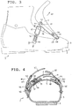
- the sole 2, the upper 3 with a longitudinal opening 9, which is covered on the inside by a tongue 18, and also the clamping lever buckles 11 provided for closing the shoe are similar to in the shoe designed according to FIGS. 1 and 2.
- the one pressure distribution plate 5 is slidably mounted on a swivel arm 26 in its longitudinal direction, which in turn runs essentially in the longitudinal direction of the shoe and is connected at its front end 27 by a bolt 28 to the upper 3 of the shoe is.
- a swivel arm 26 is preferably made of spring steel.
- the connection of the pressure distribution plate 5 to the swivel arm 26, which enables a displacement in the longitudinal direction of the shoe, is again formed by rivets 20 which engage in elongated holes 19 provided in the pressure distribution plate 5.
- the other pressure distribution plate 6 in the embodiment shown in FIGS. 3 and 4 is directly connected to the upper part 3 in a longitudinally displaceable manner, this longitudinally displaceable connection being formed again by rivets 20 which engage in corresponding elongated holes 19 in the pressure distribution plate 6.
- the pressure distribution plate 5 can in the embodiment according to FIGS. 3 and 4 on the one hand by pivoting the swivel arm 26 about the bolt 28 connecting it to the upper part 3 are pivoted outwards in the direction of the arrow 29 and, on the other hand, can be raised by elastic bending of the swivel arm 26 also in the direction of the arrow 30, so that a very extensive opening of the opening 9 in the upper part 3 is achieved can be.
- suitable elasticity can be provided by suitable choice of material.
- the swivel arm 26 In order to pull the swivel arm 26 into the position corresponding to the closed position of the shoe and to keep it fixed in this position, the swivel arm 26 is provided with a hook 31, in which a pulling element 32 of a tension lever buckle 33 which corresponds to the hook 31 on the upper of the shoe can be suspended .
- the tensioning lever buckle 33 which has a tensioning lever part 34 and a suspension part 35, serves on the one hand to pull together the upper part 3 and the pressure distribution plates 5, 6 to put the shoe in the closed position, and on the other hand to position the swivel arm 26 and the swivel arm with it connected pressure distribution plate 5 in a position provided for the closed position of the shoe.
- two tension arms are articulated on the tension lever 36 of the tension lever buckle 33, one of these tension arms forming the tension element 32, which can be engaged with the hook 31, and the other tension arm 37 for cooperation with the one on the opposite side of the shoe or the upper part 3 of the same attached hanging part 35 is provided, and is hooked into this hanging part 35 for pulling together the upper part of the shoe and pressure distribution plates.
- the positioning of the pressure distribution plate 5 and the closing or contraction of the shoe can be carried out with a single tensioning movement of the tensioning lever 36.
- various clamping elements to close or contract the shoe on the one hand and to position the swivel arm 26 on the other hand, e.g. provide two independent clamping lever buckles.
- the longitudinally displaceable connection of the pressure distribution plate 5 to the swivel arm 26 is again formed by rivets 20 which are seated firmly in the swivel arm 26 and engage in elongated holes 19 which are provided in the pressure distribution plate 5. It is of course also possible, conversely, to fix rivets 20 firmly in the pressure distribution plate and to provide slots in which these rivets engage in the swivel arm 26; in the same way, it would in principle also be possible to provide elongated holes both in the swivel arm 26 and in the pressure distribution plate 5, rivets which connect the pressure distribution plate 5 to the swivel arm 26 each running through an elongated hole in the pressure distribution plate and in the swivel arm, thus achieving a longitudinal displacement can be, which corresponds approximately to the sum of the lengths of the two elongated holes.
- ribs 22 are formed on these pressure distribution plates, which on the one hand facilitate the longitudinal displacement of the pressure distribution plates and on the other hand also provide a good seal between the outside of the Form upper part 3 and the pressure distribution plates.
- both pressure distribution plates 5, 6 can each be attached to a swivel arm 26 so as to be longitudinally displaceable and such a particularly wide opening of the entry or opening 9 of the shoes can be made possible.
- the upper 3 which, like the sole 2, is formed from plastic, is provided with an entry opening 9, which is covered by pressure distribution plates 5, 6 when the shoe is closed, which overlap each other when the shoe is closed.
- the pressure distribution plates 5, 6 run from the toe area 7 of the shoe over the instep area 4 and, bent upwards, along the front of the shoe upper 8.
- Each pressure distribution plate 5, 6 is held on the upper part 3 by a pair of lasts provided in the instep area of the shoe, which is formed from a bar 38 formed on the upper part 3 and a bar 39 formed on the pressure distribution plate 5, 6 in question.
- the two strips 38, 39 forming a pair of strips run side by side approximately in the longitudinal direction of the shoe and engage in a hook-like manner in the transverse direction, so that a connection of a pressure distribution plate is connected to each such pair of strips 5 and 6 is formed with the upper part 3 of the shoe, which on the one hand permits longitudinal displacement of the pressure distribution plate 5 or 6 in question with respect to the upper part 3, as is symbolized by the arrow 40, and on the other hand also a hinge-like pivoting about one in the respective last pair longitudinal pivot axis, so that the two strips of each pair of strips form a hinge with each other.
- stops for holding the two lasts 38, 39 to both pairs of lasts which in the case shown in the drawing are formed by parts of the clamping lever buckles 11 which are provided for closing or tightening the shoe.
- these stops are formed by bearing parts 23 of the clamping lever buckles 11, and in the case of the last shown in FIG. 6, these stops are formed by the hanging parts 13 the tension lever buckles 11 formed.
- a further possibility of holding the two strips of the strip pairs to one another in the transverse direction is the provision of an elastic form fit, as is sketched in FIG. 7.
- an elastic form fit in which, for example, a thickened edge 41 on one bar engages in an undercut groove 42 on the other bar, can be supplemented by stops or similar holding means.
Landscapes
- Health & Medical Sciences (AREA)
- General Health & Medical Sciences (AREA)
- Physical Education & Sports Medicine (AREA)
- Footwear And Its Accessory, Manufacturing Method And Apparatuses (AREA)
Applications Claiming Priority (2)
| Application Number | Priority Date | Filing Date | Title |
|---|---|---|---|
| AT1945/93 | 1993-09-27 | ||
| AT0194593A AT401332B (de) | 1993-09-27 | 1993-09-27 | Sportschuh |
Publications (2)
| Publication Number | Publication Date |
|---|---|
| EP0645100A1 true EP0645100A1 (fr) | 1995-03-29 |
| EP0645100B1 EP0645100B1 (fr) | 1997-01-08 |
Family
ID=3524435
Family Applications (1)
| Application Number | Title | Priority Date | Filing Date |
|---|---|---|---|
| EP94113727A Expired - Lifetime EP0645100B1 (fr) | 1993-09-27 | 1994-09-02 | Chaussure de sport |
Country Status (5)
| Country | Link |
|---|---|
| US (1) | US5553400A (fr) |
| EP (1) | EP0645100B1 (fr) |
| JP (1) | JP2589055B2 (fr) |
| AT (1) | AT401332B (fr) |
| DE (1) | DE59401519D1 (fr) |
Families Citing this family (6)
| Publication number | Priority date | Publication date | Assignee | Title |
|---|---|---|---|---|
| US6293566B1 (en) | 1997-01-08 | 2001-09-25 | Burton Corporation | Unitary strap for use in a soft boot snowboard binding |
| US6671982B2 (en) | 2000-03-14 | 2004-01-06 | Benetton Group S.P.A. | Shell, particularly for a ski boot |
| US7614638B2 (en) | 2004-08-02 | 2009-11-10 | The Burton Corporation | Convertible toe strap |
| FR2883138B1 (fr) * | 2005-03-15 | 2007-08-03 | Salomon Sa | Crochet sur-dimensionne |
| WO2006134617A1 (fr) * | 2005-06-16 | 2006-12-21 | Tecnica Spa | Chaussures de sport, en particulier chaussures de ski, offrant une entree et une extraction faciles du pied |
| EP1969956B1 (fr) * | 2007-03-13 | 2014-12-31 | Rossignol Lange S.R.L. | Dispositif de fermeture et serrage d'une chaussure de sport |
Citations (4)
| Publication number | Priority date | Publication date | Assignee | Title |
|---|---|---|---|---|
| DE1816811A1 (de) * | 1968-12-24 | 1970-06-25 | Josef Lederer | Skistiefel |
| US4510703A (en) * | 1982-12-17 | 1985-04-16 | Harrison Eiteljorg | Ski boot |
| EP0316540A1 (fr) * | 1987-11-20 | 1989-05-24 | Raichle Sportschuh AG | Chaussure de sport, en particulier chaussure de ski |
| EP0551881A1 (fr) * | 1992-01-16 | 1993-07-21 | NORDICA S.p.A | Article chaussant, en particulier pour la pratique du ski |
Family Cites Families (13)
| Publication number | Priority date | Publication date | Assignee | Title |
|---|---|---|---|---|
| FR1006309A (fr) * | 1948-10-02 | 1952-04-22 | Chaussure de ski | |
| FR1083590A (fr) * | 1953-06-11 | 1955-01-11 | Chaussures Chevron | Chaussures de sport |
| US3530596A (en) * | 1969-03-12 | 1970-09-29 | Raichle Boot Co Ltd | Ski boot |
| DE2341658A1 (de) * | 1972-08-23 | 1974-03-07 | Polyair Maschb Gmbh | Skischuh |
| DE7331162U (fr) * | 1972-09-01 | 1973-08-28 | Fbsas Bertele G | |
| DE3069740D1 (en) * | 1979-05-21 | 1985-01-17 | Erik Trell | A safety ski binding |
| EP0053340A3 (fr) * | 1980-11-28 | 1982-10-20 | Raichle Sportschuh AG | Chaussure de sport, en particulier chaussure de ski |
| IT1225397B (it) * | 1988-08-02 | 1990-11-13 | Nordica Spa | Struttura di scafo, particolarmente per scarponi da sci ad entrata an teriore |
| FR2640123B1 (fr) * | 1988-12-09 | 1991-08-23 | Salomon Sa | Chaussure de ski alpin |
| CH679265A5 (fr) * | 1989-09-26 | 1992-01-31 | Raichle Sportschuh Ag | |
| IT1242930B (it) * | 1990-11-07 | 1994-05-18 | Nordica Spa | Scarpone da sci. |
| IT1256291B (it) * | 1991-07-03 | 1995-11-29 | Scarpone da sci ad ingresso anteriore | |
| IT1259095B (it) * | 1992-05-06 | 1996-03-11 | Calzaturificio Tecnica Spa | Scarpone da sci biomeccanico |
-
1993
- 1993-09-27 AT AT0194593A patent/AT401332B/de not_active IP Right Cessation
-
1994
- 1994-09-02 EP EP94113727A patent/EP0645100B1/fr not_active Expired - Lifetime
- 1994-09-02 DE DE59401519T patent/DE59401519D1/de not_active Expired - Fee Related
- 1994-09-26 US US08/312,390 patent/US5553400A/en not_active Expired - Fee Related
- 1994-09-27 JP JP6231455A patent/JP2589055B2/ja not_active Expired - Fee Related
Patent Citations (4)
| Publication number | Priority date | Publication date | Assignee | Title |
|---|---|---|---|---|
| DE1816811A1 (de) * | 1968-12-24 | 1970-06-25 | Josef Lederer | Skistiefel |
| US4510703A (en) * | 1982-12-17 | 1985-04-16 | Harrison Eiteljorg | Ski boot |
| EP0316540A1 (fr) * | 1987-11-20 | 1989-05-24 | Raichle Sportschuh AG | Chaussure de sport, en particulier chaussure de ski |
| EP0551881A1 (fr) * | 1992-01-16 | 1993-07-21 | NORDICA S.p.A | Article chaussant, en particulier pour la pratique du ski |
Also Published As
| Publication number | Publication date |
|---|---|
| ATA194593A (de) | 1996-01-15 |
| US5553400A (en) | 1996-09-10 |
| DE59401519D1 (de) | 1997-02-20 |
| EP0645100B1 (fr) | 1997-01-08 |
| JP2589055B2 (ja) | 1997-03-12 |
| JPH07148003A (ja) | 1995-06-13 |
| AT401332B (de) | 1996-08-26 |
Similar Documents
| Publication | Publication Date | Title |
|---|---|---|
| DE60009019T2 (de) | Schuh mit hohem Schaft und Schnürverschluss | |
| DE2712001C2 (de) | Skistiefel | |
| DE3115529C2 (de) | Skistiefel | |
| AT402679B (de) | Skischuh | |
| DE3342121C2 (de) | Skistiefel | |
| EP0113908B1 (fr) | Chaussure de ski à jambière pivotante et réglable | |
| DE3236259C2 (de) | Skistiefel | |
| DE8333662U1 (de) | Skischuh | |
| DE2846914B1 (de) | Sicherheits-Plattenskibindung | |
| EP0053340A2 (fr) | Chaussure de sport, en particulier chaussure de ski | |
| CH577282A5 (en) | Ski boot with hinged rear ankle support - has simple fastening and tightening mechanism with interconnected tension members | |
| DE3532455A1 (de) | Verschluss- und festspanneinrichtung eines skistiefels mit einstieg von hinten | |
| DE60019225T2 (de) | Zuglasche für Reissverschluss | |
| EP0443293A1 (fr) | Chaussure de ski ajustable en taille | |
| DE3736931A1 (de) | Ski-schuh | |
| EP0645100B1 (fr) | Chaussure de sport | |
| DE3540419A1 (de) | Alpiner skistiefel | |
| EP3641581B1 (fr) | Système de laçage rapide ainsi que chaussure équipée dudit système | |
| DE69408822T2 (de) | Schischuh mit angelenkten Schaftvorderteil | |
| DE2711213A1 (de) | Kniehebelverschluss fuer stiefel | |
| EP0649610B1 (fr) | Chaussure de sport | |
| DE69402937T2 (de) | Schischuh | |
| DE3624598A1 (de) | Skibremse | |
| WO1992003071A1 (fr) | Boucle pour chaussures, notamment chaussures de ski | |
| EP0441776B1 (fr) | Chaussure monocoque de ski a tige composite |
Legal Events
| Date | Code | Title | Description |
|---|---|---|---|
| PUAI | Public reference made under article 153(3) epc to a published international application that has entered the european phase |
Free format text: ORIGINAL CODE: 0009012 |
|
| AK | Designated contracting states |
Kind code of ref document: A1 Designated state(s): CH DE FR IT LI |
|
| 17P | Request for examination filed |
Effective date: 19950929 |
|
| 17Q | First examination report despatched |
Effective date: 19951212 |
|
| GRAG | Despatch of communication of intention to grant |
Free format text: ORIGINAL CODE: EPIDOS AGRA |
|
| GRAH | Despatch of communication of intention to grant a patent |
Free format text: ORIGINAL CODE: EPIDOS IGRA |
|
| GRAH | Despatch of communication of intention to grant a patent |
Free format text: ORIGINAL CODE: EPIDOS IGRA |
|
| GRAA | (expected) grant |
Free format text: ORIGINAL CODE: 0009210 |
|
| AK | Designated contracting states |
Kind code of ref document: B1 Designated state(s): CH DE FR IT LI |
|
| PG25 | Lapsed in a contracting state [announced via postgrant information from national office to epo] |
Ref country code: IT Free format text: LAPSE BECAUSE OF FAILURE TO SUBMIT A TRANSLATION OF THE DESCRIPTION OR TO PAY THE FEE WITHIN THE PRE;WARNING: LAPSES OF ITALIAN PATENTS WITH EFFECTIVE DATE BEFORE 2007 MAY HAVE OCCURRED AT ANY TIME BEFORE 2007. THE CORRECT EFFECTIVE DATE MAY BE DIFFERENT FROM THE ONE RECORDED.SCRIBED TIME-LIMIT Effective date: 19970108 |
|
| REG | Reference to a national code |
Ref country code: CH Ref legal event code: EP |
|
| REF | Corresponds to: |
Ref document number: 59401519 Country of ref document: DE Date of ref document: 19970220 |
|
| ET | Fr: translation filed | ||
| PLBE | No opposition filed within time limit |
Free format text: ORIGINAL CODE: 0009261 |
|
| STAA | Information on the status of an ep patent application or granted ep patent |
Free format text: STATUS: NO OPPOSITION FILED WITHIN TIME LIMIT |
|
| 26N | No opposition filed | ||
| PGFP | Annual fee paid to national office [announced via postgrant information from national office to epo] |
Ref country code: CH Payment date: 20030901 Year of fee payment: 10 |
|
| PGFP | Annual fee paid to national office [announced via postgrant information from national office to epo] |
Ref country code: DE Payment date: 20030903 Year of fee payment: 10 |
|
| PGFP | Annual fee paid to national office [announced via postgrant information from national office to epo] |
Ref country code: FR Payment date: 20030904 Year of fee payment: 10 |
|
| PG25 | Lapsed in a contracting state [announced via postgrant information from national office to epo] |
Ref country code: LI Free format text: LAPSE BECAUSE OF NON-PAYMENT OF DUE FEES Effective date: 20040930 Ref country code: CH Free format text: LAPSE BECAUSE OF NON-PAYMENT OF DUE FEES Effective date: 20040930 |
|
| PG25 | Lapsed in a contracting state [announced via postgrant information from national office to epo] |
Ref country code: DE Free format text: LAPSE BECAUSE OF NON-PAYMENT OF DUE FEES Effective date: 20050401 |
|
| REG | Reference to a national code |
Ref country code: CH Ref legal event code: PL |
|
| PG25 | Lapsed in a contracting state [announced via postgrant information from national office to epo] |
Ref country code: FR Free format text: LAPSE BECAUSE OF NON-PAYMENT OF DUE FEES Effective date: 20050531 |
|
| REG | Reference to a national code |
Ref country code: FR Ref legal event code: ST |