EP0645218A2 - Tige d'outil - Google Patents
Tige d'outil Download PDFInfo
- Publication number
- EP0645218A2 EP0645218A2 EP94114758A EP94114758A EP0645218A2 EP 0645218 A2 EP0645218 A2 EP 0645218A2 EP 94114758 A EP94114758 A EP 94114758A EP 94114758 A EP94114758 A EP 94114758A EP 0645218 A2 EP0645218 A2 EP 0645218A2
- Authority
- EP
- European Patent Office
- Prior art keywords
- grooves
- tool shank
- chamfered
- flanks
- tool
- Prior art date
- Legal status (The legal status is an assumption and is not a legal conclusion. Google has not performed a legal analysis and makes no representation as to the accuracy of the status listed.)
- Withdrawn
Links
- 230000005540 biological transmission Effects 0.000 claims abstract description 3
- 230000035939 shock Effects 0.000 description 1
Images

Classifications
-
- B—PERFORMING OPERATIONS; TRANSPORTING
- B25—HAND TOOLS; PORTABLE POWER-DRIVEN TOOLS; MANIPULATORS
- B25D—PERCUSSIVE TOOLS
- B25D17/00—Details of, or accessories for, portable power-driven percussive tools
- B25D17/08—Means for retaining and guiding the tool bit, e.g. chucks allowing axial oscillation of the tool bit
- B25D17/084—Rotating chucks or sockets
- B25D17/088—Rotating chucks or sockets with radial movable locking elements co-operating with bit shafts specially adapted therefor
-
- B—PERFORMING OPERATIONS; TRANSPORTING
- B25—HAND TOOLS; PORTABLE POWER-DRIVEN TOOLS; MANIPULATORS
- B25D—PERCUSSIVE TOOLS
- B25D2217/00—Details of, or accessories for, portable power-driven percussive tools
- B25D2217/003—Details relating to chucks with radially movable locking elements
- B25D2217/0034—Details of shank profiles
-
- B—PERFORMING OPERATIONS; TRANSPORTING
- B25—HAND TOOLS; PORTABLE POWER-DRIVEN TOOLS; MANIPULATORS
- B25D—PERCUSSIVE TOOLS
- B25D2217/00—Details of, or accessories for, portable power-driven percussive tools
- B25D2217/003—Details relating to chucks with radially movable locking elements
- B25D2217/0038—Locking members of special shape
Definitions
- the invention relates to a tool shank for rotating tools with at least two diametrically opposed, axially extending grooves for receiving rotary drivers and / or locking bodies of a mechanical torque transmission device.
- Such a tool shank is e.g. known from DE-PS 25 51 125.
- the known tool shank has two fundamentally different types of grooves, namely those which open out at the end of the shank and are intended for receiving strip-shaped or wedge-shaped rotary drivers, and those which are closed on both sides in the axial direction and for receiving radially movable locking bodies in the form of Balls or cylinders are determined.
- This known tool shank has the disadvantage that it only can be used with a very specific machine system that is adapted to it, but cannot be used universally in various common machine types.
- the object of the invention is to remedy this disadvantage.
- flanks of a pair of grooves according to the invention are chamfered in a hollow cylinder only within a section which is axially delimited in both directions and ends at a certain distance from the shaft end, with not only one but basically two mutually opposite grooves having this chamfer, sufficiently large stop surfaces created for the locking body, which prevent the tool shank from unintentionally coming loose and can be pulled out of the tool holder of the machine.
- the grooves of the chamfered groove pair preferably have a greater radial depth than the grooves of the non-chamfered groove pair.
- the grooves of the chamfered pair of grooves can be wider over their entire cross-section than the grooves of the pair of chamfers not chamfered.
- flanks of the grooves preferably run radially or almost radially, but they can also run tangentially, so that the flanks are arranged at right angles to the groove base.
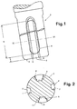
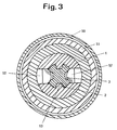
- the tool shank 1 (FIGS. 1 and 2) has four grooves 2, 3 which open out at the shank end 5 and are diametrically opposed to one another in pairs.
- the grooves 3 of one pair of grooves have a greater radial depth than the grooves 2 of the other pair of grooves.
- the grooves 3 are wider than the grooves 2 over their entire cross section.
- flanks 6 of the wider and deeper grooves 3 have a hollow cylindrical chamfer 4 within a section A which is axially delimited in both directions, section A always ending at a distance x from the shaft end 5.
- the chamfered grooves 3 are designed as "combination minutes", since they serve both to accommodate strip-shaped rotary drivers and to accommodate preferably cylindrical locking bodies.
- the flanks 6, 7 of the grooves 2, 3 run radially or almost radially.
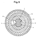
- FIG. 3 shows the use of the tool shank according to FIG. 1 in connection with the tool holder of a common machine system:
- the tool holder of a rotary hammer surrounded by the machine housing 10 is connected in a known manner (not shown) to the spindle of the electrically drivable machine, thereby on the one hand causing a Torque and on the other hand axial shocks can be transferred to the tool holder.
- the shank 1 of a tool for example a drill, chisel or adapter, which in turn has a tool receptacle that is identical or foreign to the system, e.g. can be provided with round thread, inserted.
- the locking bodies 12 engage in the chamfered grooves 3 located opposite one another on a first diagonal.
- the locking body 12 can be moved radially out of the grooves 3 by axially displacing the sleeve 11, so that the tool with the shaft 1 can be pulled out.
- the tool holder shown in Fig. 4 differs from that of Fig. 3 in that it has only one locking body 12 and only one, the locking body 12 diametrically opposite rotary driver 13, the latter engaging in the chamfered groove 3 which opens out at the shaft end 5.
- the one in the tool holder plugging shaft 1 does not differ from that according to FIG. 3; that is, the grooves 2 do not cooperate with any rotary drivers, because the tool holder has only one rotary driver 13 already mentioned.
- the tool shaft does not have four but only two diametrically opposite grooves 3, while the tool holder of the machine does not differ from that according to FIG. 4.
- One of the chamfered grooves 3 receives the locking body 12 and thus serves as a locking groove, while the opposite groove 3 receives the rotary driver 13 and serves as a rotary driving groove.
- the tool shank according to the invention can thus be used in various mounting systems without losing functionality and operational reliability.
Landscapes
- Engineering & Computer Science (AREA)
- Mechanical Engineering (AREA)
- Gripping On Spindles (AREA)
- Cutting Tools, Boring Holders, And Turrets (AREA)
- Pistons, Piston Rings, And Cylinders (AREA)
Applications Claiming Priority (2)
| Application Number | Priority Date | Filing Date | Title |
|---|---|---|---|
| DE9314416U | 1993-09-23 | ||
| DE9314416U DE9314416U1 (de) | 1993-09-23 | 1993-09-23 | Werkzeugschaft |
Publications (2)
| Publication Number | Publication Date |
|---|---|
| EP0645218A2 true EP0645218A2 (fr) | 1995-03-29 |
| EP0645218A3 EP0645218A3 (fr) | 1995-09-06 |
Family
ID=6898478
Family Applications (1)
| Application Number | Title | Priority Date | Filing Date |
|---|---|---|---|
| EP94114758A Withdrawn EP0645218A3 (fr) | 1993-09-23 | 1994-09-20 | Tige d'outil. |
Country Status (2)
| Country | Link |
|---|---|
| EP (1) | EP0645218A3 (fr) |
| DE (1) | DE9314416U1 (fr) |
Families Citing this family (5)
| Publication number | Priority date | Publication date | Assignee | Title |
|---|---|---|---|---|
| DE4341971A1 (de) * | 1993-12-09 | 1995-06-14 | Hilti Ag | Werkzeug und Werkzeugaufnahme für Handwerkzeuggeräte |
| DE4341970A1 (de) * | 1993-12-09 | 1995-06-14 | Hilti Ag | Werkzeug und Werkzeugaufnahme für Handwerkzeuggeräte |
| FI962843A7 (fi) * | 1994-01-14 | 1996-07-12 | Bosch Gmbh Robert | Käsityökalukoneiden laite työkalujen ottamiseksi mukaan pyörimiseen |
| DE4402802C2 (de) * | 1994-01-31 | 2003-01-30 | Hilti Ag | Werkzeug und Werkzeugaufnahme für Handwerkzeuggeräte |
| DE19734140A1 (de) * | 1997-08-07 | 1999-02-11 | Hawera Probst Gmbh | Bohrwerkzeug |
Family Cites Families (5)
| Publication number | Priority date | Publication date | Assignee | Title |
|---|---|---|---|---|
| DE7536182U (de) * | 1975-11-14 | 1978-02-02 | Robert Bosch Gmbh, 7000 Stuttgart | Einrichtung zur drehmomentuebertragung |
| DE3429419A1 (de) * | 1984-08-09 | 1986-02-20 | Hilti Ag, Schaan | Bohrwerkzeug fuer handbohrmaschinen |
| FR2635039B1 (fr) * | 1988-08-05 | 1990-11-02 | Prospection & Inventions | Foret comprenant une queue avec des rainures |
| DE9013190U1 (de) * | 1990-09-17 | 1992-01-23 | Drebo Werkzeugfabrik GmbH, 7963 Altshausen | Bohrer |
| DE4242452A1 (de) * | 1992-07-15 | 1994-01-20 | Hilti Ag | Werkzeug und Werkzeugaufnahme für Handwerkzeuggeräte |
-
1993
- 1993-09-23 DE DE9314416U patent/DE9314416U1/de not_active Expired - Lifetime
-
1994
- 1994-09-20 EP EP94114758A patent/EP0645218A3/fr not_active Withdrawn
Also Published As
| Publication number | Publication date |
|---|---|
| DE9314416U1 (de) | 1993-12-09 |
| EP0645218A3 (fr) | 1995-09-06 |
Similar Documents
| Publication | Publication Date | Title |
|---|---|---|
| DE3716915C2 (fr) | ||
| EP2384861B1 (fr) | Porte-outil pour un marteau perforateur | |
| EP0432169B1 (fr) | Dispositif de transmission de couple sur les machines-outils | |
| EP0500489B1 (fr) | Outil et porte-outil pour machine à main | |
| EP0433876B1 (fr) | Outil pour le forage à percussion et porte-outil pour outil de forage à percussion | |
| DE29504857U1 (de) | Bohrlehre für chirurgische Bohrwerkzeuge | |
| EP0171358A2 (fr) | Outil de forage pour perceuses à main | |
| WO1992006823A1 (fr) | Dispositif pour machines-outils manuelles | |
| EP0605602A1 (fr) | Dispositif monte sur des outils a main mecaniques. | |
| EP0147830A2 (fr) | Foret pour perceuses tenues à la main | |
| EP0551795B1 (fr) | Outil pour forage à percussion et ciselage et mandrin pour cet outil | |
| DE10058587A1 (de) | Vorrichtung zur Drehmomentübertragung | |
| EP0739267A1 (fr) | Dispositif d'entrainement en rotation d'outils pour machines-outils manuelles | |
| EP0563727B1 (fr) | Dispositif pour transmettre un moment de rotation | |
| DE102023109922A1 (de) | Bohrvorrichtung, insbesondere Saugbohrvorrichtung, zum Bohren eines Bohrloches | |
| EP0739266A1 (fr) | Dispositif d'entrainement en rotation d'outils pour machines-outils manuelles | |
| DE2346323A1 (de) | Handstueck, insbesondere fuer zahnaerztliche zwecke | |
| DE9314416U1 (de) | Werkzeugschaft | |
| DE3150966C2 (fr) | ||
| DE19725401C1 (de) | Bohrvorrichtung mit Begrenzung des Bohrweges | |
| DE10206164B4 (de) | Einspannschaft | |
| EP0665088A1 (fr) | Outil et mandrin pour outil à main | |
| DE4042399C1 (en) | Coupling sleeve between drill and drive shaft - has aperture retaining clamping stem head larger than sleeve bore | |
| EP0657253A2 (fr) | Outil et mandrin pour des outil à main | |
| DE20001865U1 (de) | Spannfutter für Werkzeugeinsätze, insbesondere Schraubendreherbits |
Legal Events
| Date | Code | Title | Description |
|---|---|---|---|
| PUAI | Public reference made under article 153(3) epc to a published international application that has entered the european phase |
Free format text: ORIGINAL CODE: 0009012 |
|
| AK | Designated contracting states |
Kind code of ref document: A2 Designated state(s): AT CH DE DK FR LI NL |
|
| PUAL | Search report despatched |
Free format text: ORIGINAL CODE: 0009013 |
|
| AK | Designated contracting states |
Kind code of ref document: A3 Designated state(s): AT CH DE DK FR LI NL |
|
| STAA | Information on the status of an ep patent application or granted ep patent |
Free format text: STATUS: THE APPLICATION IS DEEMED TO BE WITHDRAWN |
|
| 18D | Application deemed to be withdrawn |
Effective date: 19960307 |