EP0645237A2 - Dispositif pour rainer - Google Patents
Dispositif pour rainer Download PDFInfo
- Publication number
- EP0645237A2 EP0645237A2 EP94307037A EP94307037A EP0645237A2 EP 0645237 A2 EP0645237 A2 EP 0645237A2 EP 94307037 A EP94307037 A EP 94307037A EP 94307037 A EP94307037 A EP 94307037A EP 0645237 A2 EP0645237 A2 EP 0645237A2
- Authority
- EP
- European Patent Office
- Prior art keywords
- blank
- crease
- carriage
- forming
- forming die
- Prior art date
- Legal status (The legal status is an assumption and is not a legal conclusion. Google has not performed a legal analysis and makes no representation as to the accuracy of the status listed.)
- Granted
Links
Images






Classifications
-
- B—PERFORMING OPERATIONS; TRANSPORTING
- B31—MAKING ARTICLES OF PAPER, CARDBOARD OR MATERIAL WORKED IN A MANNER ANALOGOUS TO PAPER; WORKING PAPER, CARDBOARD OR MATERIAL WORKED IN A MANNER ANALOGOUS TO PAPER
- B31B—MAKING CONTAINERS OF PAPER, CARDBOARD OR MATERIAL WORKED IN A MANNER ANALOGOUS TO PAPER
- B31B50/00—Making rigid or semi-rigid containers, e.g. boxes or cartons
-
- B—PERFORMING OPERATIONS; TRANSPORTING
- B31—MAKING ARTICLES OF PAPER, CARDBOARD OR MATERIAL WORKED IN A MANNER ANALOGOUS TO PAPER; WORKING PAPER, CARDBOARD OR MATERIAL WORKED IN A MANNER ANALOGOUS TO PAPER
- B31B—MAKING CONTAINERS OF PAPER, CARDBOARD OR MATERIAL WORKED IN A MANNER ANALOGOUS TO PAPER
- B31B50/00—Making rigid or semi-rigid containers, e.g. boxes or cartons
- B31B50/25—Surface scoring
- B31B50/252—Surface scoring using presses or dies
Definitions
- THIS invention relates to a creasing unit, and in particular to a creasing unit for creasing blanks to be formed into cigarette boxes or the like.
- Stacking of the pre-printed and pre-creased sheets for transportation to the cutting and folding stations may have the effect of flattening out the creases.
- a creasing unit for creasing a blank for a box comprising:
- the creasing unit includes drive means for driving the carriage from a first blank receiving position for receiving the first blank from the feed means to a first crease forming position in which the first crease forming die and the complemental crease forming die are brought into alignment with one another.
- the unit further includes ejection means associated with the feed means, the carriage being movable to a first blank ejecting position in which the first creased blank is ejected onto a conveyor.
- the creasing unit is arranged to be interposed on a box forming machine between a magazine for holding uncreased pre-cut blanks and a blank bed conveyor for conveying the creased blanks to a folding station.
- the carriage comprises a multi-sided turret, at least one side of the turret carrying a crease forming die, and the turret being rotatable by the drive means from the first blank receiving position to the first crease forming position to the first blank ejecting position.
- the turret preferably comprises a four-sided substantially square turret having, first, second, third and fourth sides carrying respective first, second, third and fourth crease forming dies, feed means for feeding first, second, third and fourth blanks onto the first, second, third and fourth crease forming dies, retention means for holding the blanks in position on the crease forming dies, and ejection means for ejecting the creased blanks; whereby each quarter rotation of the turret by the drive means results in the first, second, third and fourth crease forming dies rotating sequentially through blank-receiving, crease-forming, blank-ejecting and idle positions.
- the feed means typically comprises a reciprocating lifting plate which is movable between a retracted position in which it is substantially flush with the crease forming die and an extended position in which it is raised from the crease forming die towards a blank magazine.
- the retaining means conveniently includes at least one suction inlet formed in the lifting plate and communicating with a vacuum source via a suction passage for sucking an exposed blank onto the lifting plate with the lifting plate extended and to hold the blank in position on the crease-forming die on retraction of the lifting plate, and valve means carried on the lifting plate and being actuable by contact with a lowermost blank in the blank magazine for opening the suction passage.
- the complemental die is carried on the press, which is in turn mounted on a reciprocal press drive mechanism, and the turret is operated by a turret drive mechanism which is mechanically linked to the press drive mechanism so as to ensure synchronicity of operation between the turret and the press.
- the invention extends to a method of forming a crease in a blank for a box comprising the steps of:
- the method preferably includes the initial step of depositing a plurality of uncreased pre-cut blanks into a magazine, and the final steps of sequentially ejecting the creased blank onto a blank bed conveyor and conveying the blanks to a folding station.
- the method includes the further steps of:
- the second blank-receiving position corresponds to the first crease-forming position
- the second crease-forming position corresponds to the first blank-ejecting position
- the method conveniently includes the step of moving the carriage to a first idle position, the first idle position corresponding to the second blank-ejecting position.
- the method preferably includes the still further steps of:
- the third blank- receiving position corresponds to the first blank-ejecting position and the second crease-forming position
- the third crease-forming position corresponds to the second blank-ejecting position
- the method includes the additional steps of:
- the fourth blank-receiving position corresponds to the third crease-forming position
- the fourth crease forming position corresponds to the third blank-ejecting position and the first blank-receiving position
- the fourth blank-ejecting position corresponds to the second blank-receiving position and the first crease-forming position
- the carriage is preferably a four-sided turret which is quarter-rotated through its various positions.
- a creasing unit 10 has at its heart a rotary turret 12 mounted to rotate clockwise in the direction of arrow 13 about a central axis 13A.
- the turret 12 which has four sides or faces 12A to 12D, is fitted to a standard Molins HLP (Hinge-Lid Pack) manufacturing machine, and is interposed between a magazine 14 and a pair of blank bed guides 16 carried on a blank bed conveyor 17.
- Molins HLP Hydrophile-Lid Pack
- Mounted on each face or side 12A to 12D of the turret are identical female die plates 18A to 18D.
- a lifting plate 20 is mounted reciprocally within each female die plate, and is arranged to move between an extended position indicated in Figure 1A and a retracted position indicated in Figure 1B.
- An independently mounted reciprocal press 22 includes a male creasing plate 24 mounted on a pair of reciprocating rams 26.
- the operation of the creasing unit 10 of the invention can briefly be described as follows.
- the magazine 14 is loaded with a stack of blanks 28 for forming cigarette boxes.
- the lifting plate 20 is raised upwardly to a position in which it abuts the lowermost first blank 28A.
- a spring pin 30 carried on the lifting plate 20 is depressed as it pushes against the lowermost blank 28A, thereby actuating several vacuum or suction inlets 32 which cause the lowermost blank 28A to be sucked firmly against an upper surface of the lifting plate 20.
- the lifting plate 20 then retracts until it is flush with the female die plate 18A, carrying the lowermost blank 28A with it.
- the turret 12 then rotates through 90° so that the female die plate 18A is in a position in which it lies adjacent the press 22.
- the press 22 is advanced forward in the direction of arrow 34, so as to cause the blank 28A to be sandwiched between the female creasing plate 18A and the male creasing plate 24.
- the female creasing plate 18A is provided with a pair of parallel channels 36 which are semi-circular in cross section.
- the male creasing plate 24 is similarly provided with a complemental pair of semi-circular ridges 38 which form a snug fit within the female channels 36 when the press 22 is extended, as is clear from Figure 1B.
- a pair of parallel semi-circular ridged corner creases 40 are thus formed in the blank 28A, as is clear from Figure 1C.
- the press is retracted in the direction of arrow 42, and the turret is 12 is rotated through a further 90° to its Figure 1C position, in which the female die plate 18A and blank 28A overlie the blank bed guide 16.
- the lifting plate 20 then extends as the suction is terminated, thereby allowing the blank 28A to fall into position on the blank bed conveyor, from where the blank is conveyed to a folding station.
- the blank creasing operation is duplicated on each consecutive side 12A to 12D for each quarter rotation of the turret 12.
- the female die plate 18A is brought into position beneath the magazine 14.
- a lifting plate 20B extends upwardly from the female creasing plate 18B and its associated vacuum inlet is actuated so as to capture the subsequent lowermost blank 28B from the magazine 14.
- the blank 28D preceding the blank 28A is being ejected onto the blank bed conveyor 17.
- the female creasing plate 18B is then brought into position adjacent the press 22 and the following female creasing plate 18C is positioned just beneath the magazine 14 in preparation for its associated lifting plate 20C to capture the next lowermost blank 28C in the stack.
- the female creasing plate 18 has a centrally positioned rectangular cut-out 42 which accommodates the rectangular lifting plate 20.
- Ten suction apertures 44 nest within elongate depressions 46 formed in the upper surface of the lifting plate so as to distribute the suction force evenly over the area of the lifting plate.
- Both the bolts for mounting the lifting plate 20 and the female creasing plate 18 have respective recessed heads 48 and 50 so as to ensure that the blank 28A lies flush with the upper surfaces of both the lifting plate 20 and the female creasing plate 18.
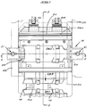
- the turret 12 is journalled onto a central stationary shaft 54 on a pair of inner bearings 56, which are fitted between the shaft 54 and a pair of circular end plates 58 and 60.
- the end plates 58 and 60 are in turn journalled on a pair of outer bearings 62 to mounting plates 64 and 66 forming part of the turret housing 52.
- the suction apertures 44 formed in each lifting plate 20 merge into passageways 70 which terminate at one end of a sprung valve 72 which is operated by means of the pin 30. Depression of the pin 30 causes the valve 72 to open, thereby allowing the passageways 70 to communicate with a central passageway 74 which extends axially through a spigot 76.
- the spigot 76 forms the innermost portion of the lifting plate 20, and nests within a complemental cylinder 78 which extends radially into one branch 79A of a central cruciform hub 80, the other three branches 79B of which have identical cylinders formed therein.
- the central hub 80 is in turn bolted to a collar 82 which surrounds and is mounted rotatably to the shaft 54.
- the collar 82 has four equispaced apertures 83A, 83B, 83C and 83D formed therein. In the position indicated in Figure 5, the aperture 83A communicates between the cylinder 78 and an almost semi-circular passageway 84 formed in the outer surface of the shaft.
- the passageway 84 terminates just short of the aperture 83C, and is arranged to communicate simultaneously with the apertures 83A and 83D.
- the passageway 84 in turn communicates with a vacuum conduit 86 which extends axially through the shaft 54 and terminates in an elbow pipe 88 which is coupled to a vacuum source.
- the semi-circular passageway 84 terminates just short of the aperture 83C. As a result, the vacuum is broken with respect to any lifting plate when it reaches the lowest eject position illustrated at 92.
- Ejection of the creased blank from the female dieplate 18D is assisted by the lowermost lifting plate 20 being in the extended position, as is shown at 93.
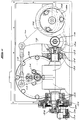
- a pair of circular cam-plates 94 and 96 are fixed within the turret to opposite ends of the shaft 54.
- an oblate camchannel 98 is formed in the outer surface of each of the cam-plates.
- Four followers 100, 100A, 100B and 100C travel within the channel 98, and are coupled to the respective lifting plates 20, 20A, 20B and 20C by respective conrods 102, 102A, 102B and 102C.
- the circular cam-plate 94 has an identical arrangement of followers and con-rods, with corresponding followers 100A and 100C arranged to lift opposite ends of the lifting plate 20 and 20B in tandem.
- the cam channel 98 is configured so that, as the turret rotates relative to the channel, the upper- and lowermost lifting plates 20 and 20B will always be extended when in the respective blank feed and blank eject positions, whilst the laterally positioned lifting plates 20A and 20C will be in the retracted respective crease forming and dormant positions, flush with their corresponding female dieplates.
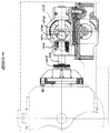
- a crank arm 112 is mounted to the end of the central shaft 54, and a crank lever 114 extends between a free end of the crank arm 112 and a crank plate 116.
- the crank plate 116 is mounted rotatably to a stub axle 118 which is carried on a bevelled gear wheel 120.
- the bevelled gear wheel 120 is in turn driven by a bevel gear 122 which is mounted to a drive shaft 124.
- the opposite end of the drive shaft 124 is fitted with a gear wheel 126 which is driven by a toothed pulley belt (not indicated) via an intermediate gear 128.
- the belt is coupled to a toothed sprocket 130.
- the drive shaft 124 is similarly journalled to the turret housing 52 on a pair of tapered bearings 132 and a double bearing wheel 134.
- the crank plate 116 carries a cam pin 136 which is arranged to travel within an elliptical channel 138 which is formed within a cam wheel 140.
- the crank plate 116 in turn drives the press 22 via a press drive mechanism.
- a drive shaft 142 extends from the centre of the cam wheel 140 to the press 22.
- a cog 144 is mounted to the drive shaft 142, and is driven via a cog 146 mounted behind the bevelled gear wheel 120.
- a further cog 148 is splined to the end of the drive shaft 142.
- the cog 148 drives a cog 150 which is carried on a stepped shaft 152.
- the stepped shaft 152 is in turn journalled to a mounting block 154 on a pair of bearings 156.
- the shaft 152 carries an eccentrically mounted cam rod 158 which is arranged to travel within a pair of cam slots 160 carried on the rams 26. It is clear how rotation of the eccentric cam rod 158 via the drive shaft 122 will cause the rams to reciprocate.
- Each ram 26 is fitted with an adjustable collar 162 which is arranged to tension or to detension a spring 164 housed at the head of each ram. By adjusting the collar 162 the extent of travel of each ram can be finely adjusted.
- An additional compression spring 166 is housed just forwardly of the slot 160 for providing compressive play in the rams.
- An advantage of the creasing unit of the invention is that it can be readily fitted to the Molins HLP machine without major modifications being required.
- the corner creases can now be formed in situ , thereby avoiding the disadvantages of separate creasing operations.
Landscapes
- Making Paper Articles (AREA)
Applications Claiming Priority (2)
| Application Number | Priority Date | Filing Date | Title |
|---|---|---|---|
| ZA937143 | 1993-09-27 | ||
| ZA937143 | 1993-09-27 |
Publications (3)
| Publication Number | Publication Date |
|---|---|
| EP0645237A2 true EP0645237A2 (fr) | 1995-03-29 |
| EP0645237A3 EP0645237A3 (fr) | 1996-03-20 |
| EP0645237B1 EP0645237B1 (fr) | 1998-07-22 |
Family
ID=25583272
Family Applications (1)
| Application Number | Title | Priority Date | Filing Date |
|---|---|---|---|
| EP94307037A Expired - Lifetime EP0645237B1 (fr) | 1993-09-27 | 1994-09-27 | Dispositif pour rainer |
Country Status (3)
| Country | Link |
|---|---|
| EP (1) | EP0645237B1 (fr) |
| DE (1) | DE69411834T2 (fr) |
| ZA (1) | ZA947520B (fr) |
Cited By (2)
| Publication number | Priority date | Publication date | Assignee | Title |
|---|---|---|---|---|
| CN106626522A (zh) * | 2016-10-12 | 2017-05-10 | 宝利华纸制品(昆山)有限公司 | 压泡机卡片定位系统 |
| CN109927351A (zh) * | 2019-04-29 | 2019-06-25 | 宜昌市综艺包装有限公司 | 自动翻转压盒机 |
Family Cites Families (5)
| Publication number | Priority date | Publication date | Assignee | Title |
|---|---|---|---|---|
| US3768950A (en) * | 1968-01-31 | 1973-10-30 | Champion Int Corp | Apparatus for scoring synthetic plastic sheet material |
| DE3302038A1 (de) * | 1983-01-22 | 1984-07-26 | Winkler & Dünnebier, Maschinenfabrik und Eisengießerei GmbH & Co KG, 5450 Neuwied | Rotierende schneidvorrichtung zur herstellung von fensterausschnitten in briefhuellen und kartonagen |
| GB8428644D0 (en) * | 1984-11-13 | 1984-12-19 | Mead Corp | Cam assembly for feeder mechanism |
| IT1185814B (it) * | 1985-06-21 | 1987-11-18 | Chierese Cartotecnica | Gruppo formatore per macchine automatiche per la formatura di scatole a partire da semilavorati appiattiti |
| DE3938480A1 (de) * | 1989-11-20 | 1991-05-23 | Hell Rudolf Dr Ing Gmbh | Vorrichtung zum aufspannen von blattfoermigem aufzeichnungsmaterial |
-
1994
- 1994-09-27 EP EP94307037A patent/EP0645237B1/fr not_active Expired - Lifetime
- 1994-09-27 DE DE69411834T patent/DE69411834T2/de not_active Expired - Lifetime
- 1994-09-27 ZA ZA947520A patent/ZA947520B/xx unknown
Cited By (2)
| Publication number | Priority date | Publication date | Assignee | Title |
|---|---|---|---|---|
| CN106626522A (zh) * | 2016-10-12 | 2017-05-10 | 宝利华纸制品(昆山)有限公司 | 压泡机卡片定位系统 |
| CN109927351A (zh) * | 2019-04-29 | 2019-06-25 | 宜昌市综艺包装有限公司 | 自动翻转压盒机 |
Also Published As
| Publication number | Publication date |
|---|---|
| EP0645237B1 (fr) | 1998-07-22 |
| ZA947520B (en) | 1995-05-29 |
| DE69411834D1 (de) | 1998-08-27 |
| EP0645237A3 (fr) | 1996-03-20 |
| DE69411834T2 (de) | 1999-01-07 |
Similar Documents
| Publication | Publication Date | Title |
|---|---|---|
| CN1141212C (zh) | 小型箱子成形机 | |
| EP2110232B1 (fr) | Dispositif d'insertion d'inserts dans des matrices d'une presse rotative pour comprimés | |
| JPS598877Y2 (ja) | プレス装置 | |
| DE4106014C2 (de) | Verfahren und Vorrichtung zum Formen, Umformen und Bördeln von Deckeln in einer einzelnen Presse | |
| EP0555515B1 (fr) | Appareil d'alimentation de feuilles amélioré pour alimenter des feuilles successives pour boîtes en carton d'une pile | |
| US6722237B2 (en) | Method for aligning and severing articles from a web of thermoformable material | |
| EP3299158B1 (fr) | Procédé et dispositif de fabrication de cartons avec rabat de fermeture | |
| DE68906003T2 (de) | Maschine, vorzugsweise eine Schachtelfüllmaschine, zum automatischen Einbringen eines Artikels, vorzugsweise einer Flasche, in eine Schachtel. | |
| US5919414A (en) | Label inserting method and apparatus | |
| EP1116661A1 (fr) | Procédé et dispositif pour fabriquer des paquets (de cigarettes) | |
| JPH0462816B2 (fr) | ||
| US4804322A (en) | Deep-drawing machine for making thermoplastic containers | |
| EP0496261B1 (fr) | Procédé et dispositif pour la fabrication des boîtes avec couvercle à charnière pourvues d'un col | |
| US5385526A (en) | Apparatus and method for packaging blanks | |
| GB2088315A (en) | Wapping machine including adjustable wrapper blank grooving and/or perforating tools | |
| JPS585778B2 (ja) | ヒンジ蓋式巻タバコ包装体に組込む肩部片を形成する装置 | |
| EP2562092A1 (fr) | Dispositif et procédé de fabrication d'emballages pour cigarettes | |
| EP1396430A2 (fr) | Procédé pour la production de boítes à couvercle rabattable | |
| CH629419A5 (de) | Verfahren und vorrichtung zur herstellung von einseitig offenen, trommelartigen behaeltern runder oder eckiger querschnittsgestalt aus voll- oder wellpappe. | |
| US3285145A (en) | Carton setting up machine | |
| EP0645237B1 (fr) | Dispositif pour rainer | |
| US4310323A (en) | Method of manufacture of H-divider containers | |
| US4315752A (en) | Manufacture of H-dividers | |
| US4220076A (en) | Manufacture of H-divider containers | |
| US3733980A (en) | Carton gluing machine and method |
Legal Events
| Date | Code | Title | Description |
|---|---|---|---|
| PUAI | Public reference made under article 153(3) epc to a published international application that has entered the european phase |
Free format text: ORIGINAL CODE: 0009012 |
|
| AK | Designated contracting states |
Kind code of ref document: A2 Designated state(s): DE FR GB IT |
|
| RIN1 | Information on inventor provided before grant (corrected) |
Inventor name: LAMM, KLAUS PETER |
|
| 17P | Request for examination filed |
Effective date: 19950718 |
|
| PUAL | Search report despatched |
Free format text: ORIGINAL CODE: 0009013 |
|
| AK | Designated contracting states |
Kind code of ref document: A3 Designated state(s): DE FR GB IT |
|
| 17Q | First examination report despatched |
Effective date: 19970513 |
|
| GRAG | Despatch of communication of intention to grant |
Free format text: ORIGINAL CODE: EPIDOS AGRA |
|
| GRAG | Despatch of communication of intention to grant |
Free format text: ORIGINAL CODE: EPIDOS AGRA |
|
| GRAH | Despatch of communication of intention to grant a patent |
Free format text: ORIGINAL CODE: EPIDOS IGRA |
|
| GRAH | Despatch of communication of intention to grant a patent |
Free format text: ORIGINAL CODE: EPIDOS IGRA |
|
| ITF | It: translation for a ep patent filed | ||
| GRAA | (expected) grant |
Free format text: ORIGINAL CODE: 0009210 |
|
| AK | Designated contracting states |
Kind code of ref document: B1 Designated state(s): DE FR GB IT |
|
| REF | Corresponds to: |
Ref document number: 69411834 Country of ref document: DE Date of ref document: 19980827 |
|
| ET | Fr: translation filed | ||
| PLBE | No opposition filed within time limit |
Free format text: ORIGINAL CODE: 0009261 |
|
| STAA | Information on the status of an ep patent application or granted ep patent |
Free format text: STATUS: NO OPPOSITION FILED WITHIN TIME LIMIT |
|
| 26N | No opposition filed | ||
| REG | Reference to a national code |
Ref country code: GB Ref legal event code: IF02 |
|
| REG | Reference to a national code |
Ref country code: GB Ref legal event code: 732E |
|
| REG | Reference to a national code |
Ref country code: FR Ref legal event code: TP |
|
| PGFP | Annual fee paid to national office [announced via postgrant information from national office to epo] |
Ref country code: DE Payment date: 20130919 Year of fee payment: 20 |
|
| PGFP | Annual fee paid to national office [announced via postgrant information from national office to epo] |
Ref country code: GB Payment date: 20130919 Year of fee payment: 20 Ref country code: FR Payment date: 20130919 Year of fee payment: 20 |
|
| PGFP | Annual fee paid to national office [announced via postgrant information from national office to epo] |
Ref country code: IT Payment date: 20130927 Year of fee payment: 20 |
|
| REG | Reference to a national code |
Ref country code: DE Ref legal event code: R071 Ref document number: 69411834 Country of ref document: DE |
|
| REG | Reference to a national code |
Ref country code: GB Ref legal event code: PE20 Expiry date: 20140926 |
|
| PG25 | Lapsed in a contracting state [announced via postgrant information from national office to epo] |
Ref country code: DE Free format text: LAPSE BECAUSE OF EXPIRATION OF PROTECTION Effective date: 20140930 |
|
| PG25 | Lapsed in a contracting state [announced via postgrant information from national office to epo] |
Ref country code: GB Free format text: LAPSE BECAUSE OF EXPIRATION OF PROTECTION Effective date: 20140926 |