EP0645254A2 - Imprimante avec un dispositif permettant d'ajuster la pression de la tête d'impression sur le cylindre - Google Patents
Imprimante avec un dispositif permettant d'ajuster la pression de la tête d'impression sur le cylindre Download PDFInfo
- Publication number
- EP0645254A2 EP0645254A2 EP94113777A EP94113777A EP0645254A2 EP 0645254 A2 EP0645254 A2 EP 0645254A2 EP 94113777 A EP94113777 A EP 94113777A EP 94113777 A EP94113777 A EP 94113777A EP 0645254 A2 EP0645254 A2 EP 0645254A2
- Authority
- EP
- European Patent Office
- Prior art keywords
- spring base
- locking
- printing machine
- machine according
- engages
- Prior art date
- Legal status (The legal status is an assumption and is not a legal conclusion. Google has not performed a legal analysis and makes no representation as to the accuracy of the status listed.)
- Withdrawn
Links
Images


Classifications
-
- B—PERFORMING OPERATIONS; TRANSPORTING
- B41—PRINTING; LINING MACHINES; TYPEWRITERS; STAMPS
- B41J—TYPEWRITERS; SELECTIVE PRINTING MECHANISMS, i.e. MECHANISMS PRINTING OTHERWISE THAN FROM A FORME; CORRECTION OF TYPOGRAPHICAL ERRORS
- B41J25/00—Actions or mechanisms not otherwise provided for
- B41J25/304—Bodily-movable mechanisms for print heads or carriages movable towards or from paper surface
- B41J25/312—Bodily-movable mechanisms for print heads or carriages movable towards or from paper surface with print pressure adjustment mechanisms, e.g. pressure-on-the paper mechanisms
Definitions
- the invention relates to a printing press with a printing roller and a print head assigned to it, which has a support that can be pressed onto the printing roller and a spring base, at least one compression spring being connected between the spring base and the support, at least the spring base on a preferably parallel to the printing roller Bearing pin is rotatably mounted, and a locking member connected to the bearing pin in a torque-locking manner engages in its locking position in a snap-in receptacle of the spring base.
- a printing press of the generic type has become known from DE 41 39 891 A1, which goes back to the same applicant.
- a thermal print head is attached to a support, which in turn is rotatably mounted on a bearing pin that runs parallel to the counterpressure roller.
- the pressure force of the print head on the counterpressure roller (to be equated with the pressure roller) is defined by a pressure spring, the opposite end of which rests on a spring base, which is also rotatably mounted on the bearing pin.
- the spring base is locked in place by a hinged wedge that is connected to the bearing pin and that is oriented parallel to the bearing pin. The latter is pivoted if the print head is to be exchanged for a new or another one, or if the print medium to be printed on is with another one, or if it has been used up, has to be replaced with a new one.
- a disadvantage is that there is no possibility of varying the pressure force of the print head, as would be desirable due to manufacturing-related tolerances and different types (especially thicknesses) of the recording media to be printed.
- the object of the invention is therefore to create a printing press which is distinguished by the possibility of varying the force transmitted from the print head to the printing roller.
- an azimuthally adjustable adjustment piece is attached to the free end of the bearing pin, on which the locking member is mounted.
- the adjusting piece which assumes the intended position relative to the bearing pin after a corresponding adjustment process, is adjustable in the azimuthal direction and connected to the free end of the bearing pin and to the locking member. If the contact pressure is to be changed, the adjustment piece is loosened and brought into a new azimuthal rotational position relative to the bearing pin. After this, the adjustment piece is locked and the orientation of the locking member is then also predetermined, which in turn determines the rotational position of the spring base and thus the adaptation of the support to the printing roller, that is to say the pressing force of the printing head.
- a very special advantage of the invention is that you can first make a basic setting of the spring base with respect to the support with or without the counter pressure spring, which is completely independent of all for this relevant tolerances. With the help of an appropriate gauge, you can determine the height distance of the spring base from the support and then lock the adjusting bolt on the bearing bolt. If you then insert the spring and the locking element is engaged in the spring base, the same contact pressure of the support on the printing roller or the printing medium is guaranteed regardless of the manufacturing tolerances for each printing machine.
- the adjustment piece is a bolt which is connected centrally to the free end of the bearing bolt.
- a preferred variant of the invention describes claim 3.
- the adjustment bolt mentioned there is simple to manufacture, easy to assemble and just as easy to adjust. In addition, it is characterized by a low weight and a small space requirement.
- the fastening screw with the help of which the adjusting bolt is held on the bearing bolt, is also used for tightening the adjusting bolt on the bearing bolt, i.e. the former is held on the latter by an axial clamping action. A slight loosening of the fastening screw cancels the clamping effect, so that the adjusting bolt can be turned on the bearing bolt by the intended amount. When this setting is complete, the fastening screw is screwed back in tightly in order to achieve a clamping effect again.
- the adjusting piece is flattened over a partial length to form two parallel wrench flats, and that the locking member has a keyhole-like opening, the circular part of which has a diameter approximately corresponding to the diameter of the adjusting piece, while the width of the narrow opening part corresponds approximately to the distance between the key surfaces.
- the printhead can be easily removed from the bearing pin. Conversely, this printhead or another can be quickly pushed back onto the bearing pin and then held in its working position with the aid of the locking member, in which it is pressed against the pressure roller with the necessary pressure with the interposition of the pressure medium.
- the locking member can only lock in a pre-determined or set position in a snap-in receptacle of the spring base of the printhead, with this on the pressure roller support is under the tension of the compression spring. If the locking member is brought into an unlocked position, the load spring can relax and this then also allows the support to be lifted off the printing roller, so that the printing medium can be exchanged for another one or, when it is completely used up, for a new one. Then you put the support back on the print medium. After pivoting the spring base, with simultaneous tensioning of the loading spring, when the intended spring tension is reached, the locking member is brought into its locked position due to a certain rotational position of the spring base, so that the spring base can only maintain the rotational position now reached on the bearing pin.
- the bearing pin is stationary or, if necessary, exchangeable on a frame or the like. mounted on the printing press.
- the advantages consist primarily in the easy and inexpensive manufacturability of the locking member and in the low deformability, which are a consequence of its orientation orthogonal to the axis of the bearing pin.
- the locking member has at least one locking projection projecting transversely to its plane, which in the locked position engages in a groove-shaped snap-in receptacle of the spring base. Unlocking is done by moving the locking member on the adjusting bolt so that the locking projection emerges from the receiving groove of the spring base. The compression spring can then relax, as I said.
- the spring base is mounted hinge-like on the bearing bolt, there is an alternative to a keyhole-shaped locking member, the possibility of forming the latter very simply and inexpensively by pivoting a lever on the free end face of the adjusting piece, which lever for locking the spring base in a the adjacent end face of the spring base engages in a groove-shaped snap-in receptacle.
- This embodiment makes it possible in a simple manner to arrange the groove-shaped snap-in receptacle on the end face of the spring base in such a way that the support can be locked in a pivoting position when the lever engages in the snap-in receptacle, in which the healing elements of the printhead on the printing roller or on one on the Print roller lying record carriers are held in plant.
- a second groove-shaped snap-in receptacle of the spring base allows the support to be locked in another pivoting position when the lever engages in the further snap-in receptacle, in which the print head is lifted off the printing roller.
- a particularly compact embodiment results from the fact that the support is arranged coaxially to the spring base on the bearing pin.
- a particularly preferred variant provides that the support is provided with a bearing sleeve pushed onto the bearing pin and a sleeve-like extension of the spring base is pushed onto the bearing sleeve of the support.
- the bearing sleeve and the sleeve-like extension have essentially the same length as the bearing pin, ie they extend over its entire length. With the spring base locked, however, there must be enough play in the axial direction that the spring force can affect the support.
- the bearing pin is equipped with a somewhat reduced diameter over most of its length in order to keep the friction as small as possible.
- a printing machine e.g. a thermal printer, inkjet printer, etc.
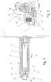
- a bearing pin 2 is attached, which is most clearly shown in Figure 3.
- a pressure roller 3 is mounted parallel to its geometric axis. Between this and a print head 4 (e.g. in FIG. 2) the print medium runs, which is pressed against the print roller 3 by a support 5 of the print head 4.
- the print medium is the running strand, for example a paper roll or a carrier with labels.
- the support 5 and a spring base 6 together with a spring 7 form the most important components of the print head 4. Because in the position of use, as will be explained in more detail later, the spring base 6 assumes a fixed position relative to the frame 1, the spring 7 presses, which preferably is designed as a helical compression spring, the support 5 against the pressure roller 3. Here, as a comparison of FIGS. 4 and 5 shows, the spring force is greater the closer the left free end of the spring base 6 is to the support 5. E.g. when printing thicker or stiffer print media a high contact pressure is required.
- the spring base 6 has a sleeve-like extension 8, the length of which corresponds approximately to that of the bearing pin 2. In this way it is pivotally mounted on the bearing pin 2 in the direction of the double arrow 9.
- storage is advantageously not carried out directly on the bearing pin 2, rather a bearing sleeve 10 of the support 5 is connected between the sleeve-like extension 8 of the spring base 6 and the bearing pin 2.
- Their length also corresponds essentially to the length of the bearing pin.
- the bearing sleeve 10 completely surrounds the bearing pin 2 at 360 °
- the sleeve-like extension 8 is designed as a type of longitudinally slotted sleeve. This can be seen, for example, from FIG. 2.
- FIG. 3 At the left or free end of the bearing pin 2 in FIG. 3 there is an adjusting piece, which in the exemplary embodiments is designed as an adjusting pin 11.
- a slide-like locking member interacts with this in the manner explained below.
- FIGS. 6 and 7 there are two parallel key surfaces 13, 14 on the adjusting bolt 11, of which only the one pointing upwards can be seen. If the adjustment bolt 11 is now pressed firmly onto the front end of the bearing bolt 2 by means of a fastening screw 15 (FIG. 3) or 16 (FIG. 7), the two wrench surfaces 13, 14 assume a very specific position, without loosening the fastening screw 15 , 16 cannot be changed. E.g. the two key surfaces 13 and 14 run parallel to the vertical according to FIG. Accordingly, in FIG.
- the slide-like locking member 12 can only be moved up and down in the direction of the double arrow 17, that is to say exactly in the vertical direction. It is obvious that one by slightly turning the adjusting bolt 11 clockwise or counterclockwise, the key surfaces 13, 14 can be inclined relative to the vertical, as a result of which the direction of displacement 17 is no longer directed in the vertical direction, but obliquely to the top left or right.
- the slide-like locking member 12 consists essentially of a flat plate with an opening 18 and a locking projection 19 projecting transversely to its plane. As shown in FIGS. 2 and 3, this engages from above in a groove-shaped snap-in receptacle 20 of the spring base 6 a. If the spring base 6 is brought into a suitable rotational position, the slider-like locking member 12 held up can slide downward along the key surfaces 13 and 14, for example due to its own weight, so that the locking projection 19 then enters the groove-shaped latching receptacle 20. However, because the slide-like locking member 12 is prevented from rotating by the adjusting bolt 11, the spring base 6 can no longer leave the rotational position on the bearing bolt 2 which is suitable for the locking position. As a result, the compression spring 7 is tensioned and the support 5 is pressed against the pressure roller 3 in accordance with the spring tension.
- the slide-like locking member 12 has a keyhole-shaped opening 18. It consists of the circular part 21 and a narrow opening part 22 merging into it. In the exemplary embodiment, the latter is arranged symmetrically to the longitudinal central axis 23 and this also applies there to the Locking approach 19.
- the diameter of the circular part 21 corresponds to that of the adjusting bolt 11 and, in the exemplary embodiment, also of the bearing bolt 2 with the usual play 3 shows that the bearing pin 2 has a smaller diameter over most of its length, more precisely over an inner region, in order to keep the contact surfaces and thus also the friction small.
- the locking projection 19 is also arranged symmetrically to the longitudinal central axis 23, but the longitudinal axis of the narrow breakthrough part 22 forms an angle 24 with the longitudinal axis 23 there, which is shown in the drawing in an exaggerated manner for clarity and, for example, in FIG Order of 5 °.
- the same relative position of the adjusting bolt 11 with respect to the bearing bolt 2 is assumed in each case.
- the slide-like locking member 12 of FIG. 10 is in a sense a double-sided locking member, because in addition to the locking shoulder 19 it also has an opposite locking shoulder 19a.
- the narrow breakthrough part 22 in addition to the narrow breakthrough part 22, there is also another narrow breakthrough part 22a, which likewise opens into the circular part 21.
- the locking projection 19 and the two narrow breakthrough parts 22 and 22a which are in extension from one another lie on the geometric longitudinal central axis 23, the locking projection 19a is offset at an angle thereto, for example by half a width of the locking projection. This in turn corresponds to the angle 24 of FIG. 9. Accordingly, starting from the one position of use after unlocking, the locking member 12 can be rotated by half a turn and then transferred back to the locked position, thereby increasing or weakening the spring tension in the sense of the above statements contains.
- the narrow breakthrough parts 22 and 22a in the exemplary embodiment in FIGS. 4 and 5 are offset from one another by 90 °. This also applies approximately to the two locking lugs 19 and 19a. To be more precise, it is the case that the centers of the two locking lugs 19 and 19a enclose an angle of preferably approximately 85 ° or, in other words, that the locking lug 19a is offset by approximately 5 ° with respect to the longitudinal central axis of the narrow breakthrough part 22a after the locking lug 19 is. Referring to FIG.
- the narrow breakthrough part 22 can also be arranged symmetrically to the longitudinal central axis 23 and in this case the locking projection 19 is then offset by an angle 24 with respect to the longitudinal central axis 23. It can be seen from FIGS. 4 and 5 that due to this small angular misalignment in FIG. 5, when using the locking projection 19a, the spring base 6 is pivoted more strongly towards the support 5 and thus the spring 7 is more tensioned there. It remains to be added for the sake of order that the width of the key surfaces 13 and 14 measured in the axial direction corresponds approximately to the thickness of the slide-like locking member 12.
- the adjusting bolt 11 of the exemplary embodiments according to FIGS. 6 and 7 has a centering bolt 25 which, according to FIG. 3, engages in a central blind bore 26 provided at the free end of the bearing bolt 2. At the bottom of this blind bore there is a threaded bore 27 into which the bolt thread 28 of the fastening screw 15 or 16 is screwed. While in the exemplary embodiment according to FIGS. 3 and 6, a conventional screw, in particular an Allen screw, is used 7, the embodiment of FIG. 7 provides for the use of a screw 16 with a washer 29. The effect of the disk 29 corresponds to the collar 30 of the adjusting bolt 11 in FIG. 6.
- An outer groove 31 is provided on the end of the adjusting bolt 11 which is remote from the bearing pin in use.
- this external groove 31 is formed by the collar 29 of the fastening screw 16 and the pin 32 and the flank 33 at the transition from the larger diameter to the pin 32.
- the outer groove 31 serves to receive the hook-like end 34 of a sash 35, which is pivotably mounted on the frame 1 in the sense of the double arrow 36. In this way, instead of a flying bearing, a "support" supported on both ends is obtained, which ensures that the printing medium is properly pressed onto the printing roller 3.
- the pivot bearing of the sash 35 is designed as an adjustable eccentric 44.
- the sash 35 must also be pivoted into an ineffective position, that is to say a pivoting movement in the counterclockwise direction.
- An unintentional displacement of the locking member 12 into the removal position is prevented by a latch 45 (FIG. 9) which crosses the opening 18 transversely.
- This bolt 45 is detachably fixed to the locking member 12, for example with two screws.
- pushbuttons 42 and 43 for pushing up and thus for unlatching the slide-like locking member 12, the gripping surface being corrugated or similarly designed to be non-slip.
- the support 5 is connected to its bearing sleeve 10 via the longitudinal bar 37.
- the sleeve-like extension 8 of the spring base 6 mounted on the bearing sleeve 10 has an inner diameter which is approximately equal to the outer diameter of the bearing sleeve 10.
- the bearing sleeve 10 has a continuous slot on its underside, the circular dimension of which is greater than the thickness of the support 5, so that the slot serves as a stop and permits a relative movement of the support which is limited as a result.
- a pivotable lever is used for azimuthal fixation of the spring base 6 46, which is connected to the bearing pin 2 via an axis 47 corresponding to the pivot axis.
- the lever 46 has an elongated hole 48, the diameter of which is dimensioned such that the pin-like axis 47 can be passed easily.
- Two end-side locking exceptions 20, 20 'of the sleeve-like extension 8 of the support 6 take up the lever in the locked position in order to fix the spring base azimuthally.
- the second groove-shaped latching recess 20 ′ allows the print head 4 to be locked in a position lifted off the print roller 3. In contrast, its printing position corresponds to the rest stop 20.
Landscapes
- Common Mechanisms (AREA)
Applications Claiming Priority (4)
| Application Number | Priority Date | Filing Date | Title |
|---|---|---|---|
| DE4332602A DE4332602C2 (de) | 1993-09-24 | 1993-09-24 | Druckmaschine mit Druckwalze und Druckkopf |
| DE19934332576 DE4332576A1 (de) | 1993-09-24 | 1993-09-24 | Thermodruckkopfhalterung |
| DE4332602 | 1993-09-24 | ||
| DE4332576 | 1993-09-24 |
Publications (2)
| Publication Number | Publication Date |
|---|---|
| EP0645254A2 true EP0645254A2 (fr) | 1995-03-29 |
| EP0645254A3 EP0645254A3 (fr) | 1995-12-20 |
Family
ID=25929861
Family Applications (1)
| Application Number | Title | Priority Date | Filing Date |
|---|---|---|---|
| EP94113777A Withdrawn EP0645254A3 (fr) | 1993-09-24 | 1994-09-02 | Imprimante avec un dispositif permettant d'ajuster la pression de la tête d'impression sur le cylindre. |
Country Status (1)
| Country | Link |
|---|---|
| EP (1) | EP0645254A3 (fr) |
Cited By (3)
| Publication number | Priority date | Publication date | Assignee | Title |
|---|---|---|---|---|
| CN103442897A (zh) * | 2010-10-28 | 2013-12-11 | Zih公司 | 具有打印头组件、离合器组件、以及打印机色带运输组件的打印机 |
| CN111332693A (zh) * | 2020-03-10 | 2020-06-26 | 冯继超 | 一种市政工程用的下水道格栅板搬运装置 |
| CN116141832A (zh) * | 2022-12-30 | 2023-05-23 | 武汉精臣智慧标识科技有限公司 | 一种打印机 |
Family Cites Families (4)
| Publication number | Priority date | Publication date | Assignee | Title |
|---|---|---|---|---|
| US4300844A (en) * | 1979-08-22 | 1981-11-17 | Hewlett-Packard Company | Moving head printer mechanism |
| JPS6273978A (ja) * | 1985-09-26 | 1987-04-04 | Brother Ind Ltd | 印字装置 |
| DE69106946T2 (de) * | 1990-06-26 | 1995-07-06 | Seiko Epson Corp | Thermozeilendrucker. |
| DE4139891C2 (de) * | 1991-12-04 | 1996-05-09 | Esselte Meto Int Gmbh | Halterungsanordnung für einen Thermodruckkopf |
-
1994
- 1994-09-02 EP EP94113777A patent/EP0645254A3/fr not_active Withdrawn
Cited By (6)
| Publication number | Priority date | Publication date | Assignee | Title |
|---|---|---|---|---|
| CN103442897A (zh) * | 2010-10-28 | 2013-12-11 | Zih公司 | 具有打印头组件、离合器组件、以及打印机色带运输组件的打印机 |
| CN103442897B (zh) * | 2010-10-28 | 2015-09-30 | Zih公司 | 具有打印头组件、离合器组件、以及打印机色带运输组件的打印机 |
| US9211705B2 (en) | 2010-10-28 | 2015-12-15 | Zih Corp. | Printer with printhead assembly, clutch assembly, and printer ribbon transport assembly |
| CN111332693A (zh) * | 2020-03-10 | 2020-06-26 | 冯继超 | 一种市政工程用的下水道格栅板搬运装置 |
| CN111332693B (zh) * | 2020-03-10 | 2021-06-01 | 南京幸庄科技创新产业园管理有限公司 | 一种市政工程用的下水道格栅板搬运装置 |
| CN116141832A (zh) * | 2022-12-30 | 2023-05-23 | 武汉精臣智慧标识科技有限公司 | 一种打印机 |
Also Published As
| Publication number | Publication date |
|---|---|
| EP0645254A3 (fr) | 1995-12-20 |
Similar Documents
| Publication | Publication Date | Title |
|---|---|---|
| DE69319849T2 (de) | Sägeblatt-Spannfutter | |
| EP0627507B1 (fr) | Machine de cardage avec chapeaux mobiles | |
| DE4332602C2 (de) | Druckmaschine mit Druckwalze und Druckkopf | |
| DE4137927A1 (de) | Anordnung zur loesbaren und positionsgenauen halterung von ausruestungs- oder zubehoerkomponenten an schraubstockbacken | |
| DE2912881A1 (de) | Treibstangenverschluss, insbesondere fuer zweifluegelige feuerschutztueren | |
| EP0308566B1 (fr) | Machine de bureau, en particulier imprimante à matrice de points, avec ajustement de l'écart entre la tête d'impression et le cylindre de frappe | |
| EP0860571B1 (fr) | Paumelle pour portes, fenêtres ou similaires | |
| EP1278641B1 (fr) | Dispositif d'impression | |
| EP0645254A2 (fr) | Imprimante avec un dispositif permettant d'ajuster la pression de la tête d'impression sur le cylindre | |
| EP0124008A2 (fr) | Dispositif de tension de plaques d'impression | |
| EP0398196B1 (fr) | Arrêt pour porte à force d'arrêt réglable | |
| DE3546253A1 (de) | Band fuer tueren, fenster und dergleichen | |
| EP2304148B1 (fr) | Système de bande | |
| DE4209084A1 (de) | Werkzeughalterung fuer schneidkoerper | |
| DE3923639C2 (de) | Bodentürschließer für eine Schwenktür | |
| DE19814628A1 (de) | Vorrichtung zum Antreiben einer Spannvorrichtung zum Fixieren einer Platte auf einem Plattenzylinder einer Druckmaschine | |
| EP0741021B1 (fr) | Dispositif d'assemblage des dispositifs de serrage avec une traverse d'un cylindre de forme | |
| DE3101648A1 (de) | Papiervorschubeinrichtung | |
| DE10309946A1 (de) | Schloß | |
| DE9113128U1 (de) | Gestell aus mit Verbindungsschlössern verbundenen Profilstangen | |
| DE3151224A1 (de) | Vorrichtung zur befestigung eines getriebes an einem rahmen von fenstern, tueren oder dergleichen | |
| DE2905317C2 (de) | Schalttafelgerät mit einem Befestigungselement | |
| DE3707313A1 (de) | Schliesszylinder fuer moebel | |
| DE20106561U1 (de) | Vorrichtung zum Verbinden von Profilstäben | |
| EP0199270A2 (fr) | Dispositif pour maintenir une porte ou une fenêtre entrouverte dans au moins une position |
Legal Events
| Date | Code | Title | Description |
|---|---|---|---|
| PUAI | Public reference made under article 153(3) epc to a published international application that has entered the european phase |
Free format text: ORIGINAL CODE: 0009012 |
|
| AK | Designated contracting states |
Kind code of ref document: A2 Designated state(s): DE DK ES FR GB IT NL SE |
|
| PUAL | Search report despatched |
Free format text: ORIGINAL CODE: 0009013 |
|
| AK | Designated contracting states |
Kind code of ref document: A3 Designated state(s): DE DK ES FR GB IT NL SE |
|
| 17P | Request for examination filed |
Effective date: 19960117 |
|
| STAA | Information on the status of an ep patent application or granted ep patent |
Free format text: STATUS: THE APPLICATION HAS BEEN WITHDRAWN |
|
| 18W | Application withdrawn |
Withdrawal date: 19961105 |