EP0645481A1 - Métier à filer ou à retordre à anneau et une méthode pour enlever un enroulement de fil textile - Google Patents
Métier à filer ou à retordre à anneau et une méthode pour enlever un enroulement de fil textile Download PDFInfo
- Publication number
- EP0645481A1 EP0645481A1 EP94306712A EP94306712A EP0645481A1 EP 0645481 A1 EP0645481 A1 EP 0645481A1 EP 94306712 A EP94306712 A EP 94306712A EP 94306712 A EP94306712 A EP 94306712A EP 0645481 A1 EP0645481 A1 EP 0645481A1
- Authority
- EP
- European Patent Office
- Prior art keywords
- spindle
- yarn
- winding member
- reserve winding
- reserve
- Prior art date
- Legal status (The legal status is an assumption and is not a legal conclusion. Google has not performed a legal analysis and makes no representation as to the accuracy of the status listed.)
- Withdrawn
Links
Images




Classifications
-
- D—TEXTILES; PAPER
- D01—NATURAL OR MAN-MADE THREADS OR FIBRES; SPINNING
- D01H—SPINNING OR TWISTING
- D01H1/00—Spinning or twisting machines in which the product is wound-up continuously
- D01H1/14—Details
- D01H1/38—Arrangements for winding reserve lengths of yarn on take-up packages or spindles, e.g. transfer tails
Definitions
- This invention relates to textile yarn ring spinning, twisting or doubling apparatus wherein the yarn is wound on a tube carried by a driven spindle, the yarn being wound around the tube to form a yarn package.
- textile yarn is intended to encompass both natural and artificial material including filaments.
- the invention may be particularly advantageously practised in textile machines of the ring spinning and twisting type which have a large number of driven spindles and are provided with automatic bobbin doffing and donning apparatus.
- the yarn passes from delivery rollers through a traveller to a yarn tube or bobbin, carried on the rotating spindle, on which the yarn is to be wound.
- the traveller is rotated around a traveller ring, which is coaxial with the spindle, by the pull of the yarn and either the spindle may gradually move axially relative to the ring or the ring to the spindle so that the yarn package is formed along the length of the tube on the spindle this movement being superimposed upon a relative reciprocating movement over the length of the nose of the package.
- the ring rail When the wound package is doffed and a fresh tube or bobbin is refixed on the spindle, the ring rail is moved back in position to form a new yarn package on the new tube.
- the yarn leading from the underwind is thus connected to the first few windings around the new tube, after which the connecting length of yarn is severed and the waste undercoil removed. It is time consuming to remove these underwinds but if they are allowed to accumulate, the spinning or winding operation can be disrupted.
- Apparatus for rupturing or severing the yarn between the bobbin and the undercoils is disclosed in our European Patent Application, No. EP-A-0304240, which discloses a yarn ring spinning apparatus in which a yarn severing device is positioned adjacent the axis of the spindle and between the reserve winding member, or sleeve, and an adjacent portion of the spindle on which the end of the yarn package is located and means are provided to produce relative rotation between the reserve winding member and the severing device so as to sever the yarn extending between the reserve winding member and the yarn package. Means are also disclosed for removing the waste undercoils from the reserve winding member.
- This doffing time (down-time) is still further increased in stopping the spinning operation of the machine in order to remove the waste undercoils from the underwind sleeves whether manually or automatically, as described in the above mentioned patent application, consequently it is common practice to allow the waste undercoils to accumulate and to remove them only, for example, every third or fourth doff. Furthermore, sometimes the opposite ends of an undercoil may become entwined which further increases the time required to remove it from the underwind sleeve and thus the loss in spinning time.
- the accumulation of waste undercoils on the reserve winding sleeve can exacerbate out of balance loads being applied to the spinning sleeve.
- the spinning operation is carried out at high spindle spinning speeds and such out of balance loads result in rapid and unacceptable wear of the apparatus and also produces unacceptably high levels of vibration and noise, particularly when the sleeve is mounted loosely on the spindle and is rotated with the spindle by frictional contact therebetween.
- a textile yarn ring spinning or twisting apparatus comprises a spindle for carrying a yarn support tube, the spindle being rotatable about its axis to enable yarn to be wound on the tube to form a yarn package, a yarn reserve winding member mounted coaxially with the spindle around which member yarn may be wound prior to the doffing of a wound yarn package from the spindle and clutch means to selectively clutch the reserve winding member to the spindle so that with the clutch means in a first position the reserve winding member is constrained to rotate with the spindle and in a second position the reserve winding member is substantially disengaged from the spindle and free to rotate relative thereto.
- the reserve windings when the reserve winding member is clutched, or coupled, to the spindle the reserve windings can be wound around the reserve winding member and, when the reserve winding member is declutched, or decoupled, from the spindle, the yarn connecting the reserve windings to the yarn package on the spindle can be parted, so that the yarn package may be doffed, and the waste reserve windings can be removed from the reserve winding member without interrupting the winding of the yarn onto a new bobbin, or tube.
- the waste underwinds which remain wrapped around the reserve winding member can be removed from the reserve winding member, either manually or automatically, whilst the spinning operation is proceeding and yarn is being wound onto a new bobbin on the spindle.
- the reserve winding member may be selectively coupled to or decoupled from the spindle simply by moving the reserve winding member along the axis of the spindle so that the clutch surfaces contact, or move apart from, each other.
- a blade is mounted to the spindle in such a position as to sever the yarn when the clutch means is in the second position and the reserve winding member is disengaged from the spindle.
- a yarn locator may be provided, preferably in the form of a recessed gear wheel type blade guard mounted to the reserve winding member, to catch the yarn extending between the bobbin on the spindle and the reserve windings between the teeth of the blade guard, when the clutch means is in the second position, and to bring the yarn against the edge of the blade to sever the yarn when the spindle is rotated relative to the reserve winding member.
- the recessed gear wheel may suitably be configured to act as a guard for the blade.
- a method of doffing a fully-wound textile yarn package from a yarn ring spinning apparatus comprises the steps of coupling a reserve winding member so as to rotate coaxially with the spindle of the apparatus, winding a number of undercoils on the reserve winding member, uncoupling the reserve winding member from the spindle so that the spindle can be rotated relative to the reserve winding member in order to part the yarn extending between the yarn package and the reserve winding member, doffing the yarn package, fixing a new bobbin tube onto the spindle and recommencing the yarn spinning operation whilst keeping the reserve winding member decoupled from the spindle and removing the waste undercoils from the reserve winding member.
- a typical yarn ring spinning machine comprises 200 or more such spindle assemblies, mounted in ranks or rows, perpendicular to the plane of the Figures.
- the spindle 1 is mounted for rotation at its lower end, or shank, 1' in a frame support housing 7, only the upper fork of which is illustrated. It is driven through a pulley 5, fixed to the spindle, by a belt 3 which may serve to drive two adjacent spindles.
- the type of drive is, however, incidental and it may for example, be in the form of an individual motor for each spindle or a tangential belt driving all the spindles.
- the upper part of the spindle 1 is not illustrated in Figures 1 and 2, but the bobbin tube 2 locates over a boss 6 and abuts against a collar 4. There is another boss at the upper end of the spindle to locate with the upper end of the bobbin tube (not shown).
- a circular blade 60 coaxial with the spindle 1 is attached by small counter-sunk headed screws (not shown) to the underside of the collar 4, so as to rotate with the spindle 1. Also fixed to the shank 1' of the spindle 1 are clutch cones 17,19.
- the lower end of the yarn package 8 is also illustrated, it being understood that the yarn is wound around the tube 2 by a traveller 37 (as shown in Figure 2) which is rotated on a traveller ring 57 (see Figure 3). This is conventional ring spinning practice.
- the reserve winding components comprise an underwind sleeve 9, or reserve winding member, which is mounted coaxial with the spindle and in the position illustrated in Figure 1 is located in a bush 11.
- a blade guard in the form of a recessed gear wheel 47 is fixed to the top of the underwind sleeve 9 the recess being of a larger diameter than that of the blade 60 and the root diameter of the teeth of the gear wheel 47 is smaller than the diameter of the blade 60.
- the bore of the bush 11 at its upper and lower ends tapers downwardly and inwardly at 18, 20 and the underwind sleeve 9 has co-operating conical portions 14,16 which locate in the tapered portions 18,20 of the bush 11.
- the bush 11 locates for sliding movement in an axial direction in a main support boss 13.
- the boss 13 is screwed to a rail 15 on the machine and the lower shank 1' of the spindle 1 passes through a bore in the rail 15, which is larger in diameter than the shank 1' of the spindle 1.
- the rails 15 extend end to end and lengthwise of the machine, each rail 15 accommodates a number of underwind assemblies at the appropriate spindle pitch.
- the position of the bush 11 is controlled by a bar 29 which extends along the length of the machine parallel with the spindles, into the plane of the drawings.
- the positional height of this bar 29 is controlled by a suitable mechanism (not illustrated) and the bar 29 carries a locating rail 21 which is shaped to provide a number of collars 44 at the pitch of the spindles 1 and which locate in a recess 23 formed by a reduced neck on the top face of the bush 11 and capped by a cap 25 which is fixed to the top face of the bush 11 by screws (not illustrated).
- the bush 11 holds the underwind sleeve 9 clear of the clutch cones 17,19 so that the spindle 1 can rotate independently of the underwind sleeve 9.
- a further bar 35 which extends along the length of the machine parallel with the spindles 1 (into the plane of the drawings) and upon which is mounted stopper brackets 33 at the pitch of the spindles.
- the stopper bracket 33 In the position shown in Figure 2 when the underwind sleeve 9 is clutched to the spindle 1 the stopper bracket 33 is above a pin 31 which is fixed into the side of the underwind sleeve 9 (there are usually three such pins evenly spaced around the body of the sleeve 9 but for clarity only one is shown in Figure 2).
- the position of Figure 1 i.e.
- the pin 31 will engage the stopper bracket 33 so as to permit the underwind sleeve only part rotation.
- the stopper bracket 33 may, if desired, be moved clear of the pins 31, so as to permit free rotation of the underwind sleeve 9, by sliding the bar 3 just a short distance lengthwise of the machine so as to take the stopper brackets 33 out of the rotary path of the pins 31.
- the stopper may be formed on the upper face of the cap 25 and the play between the underwind sleeve 9 and the bush 11 may be such as to ensure that the stopper is clear of the pin 31 in the lower position.
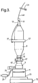
- Figure 3 illustrates the disposition of the parts as the package 8 of yarn on the bobbin tube 2 reaches full size.
- the yarn 49 coming from the front delivery rollers (not illustrated) of the machine passes through the lappet guide 53 to the top of the spindle 1 which in this particular instance has a balloon restricting head piece 55 around which the yarn spirals before passing to the traveller 37 which is mounted for rotation about the spindle on the vertically reciprocating traveller ring 57 in conventional manner.
- the underwind sleeve 9 is in the raised position of Figure 1, so as to be declutched from the spindle 1 so as not to rotate with it, the rotary blade 60 being shrouded by the guard 47.
- the bar 29 which controls the height of the underwind sleeve 9 is, of course, in its raised position as illustrated by the arrow.
- the spindle 1 then stops and the control bar 29 moves upwardly so as to cause the underwind sleeve 9 to be declutched from the spindle 1 ( Figures 1 & 5).
- the spindle 1 is then rotated (normally one turn is sufficient but it may if desired make two or three turns) so as to cause the edge of the blade 60 to slice across and cut the yarn 49 that connects the yarn on the bobbin tube 2 to that on the underwind sleeve 9, the underwind sleeve 9 being stationary during this brief rotation of the spindle 1. Any tendency for the pull of the yarn 49 across the blade 60 also to rotate the underwind sleeve 9 will be prevented when the pin 31 in the side of the sleeve 9 engages the stopper bracket 33. As mentioned above, there may be three such pins so that any tendency for the sleeve 9 to rotate will be checked before the sleeve 9 can make, at most, one third of a revolution.
- the yarn locates between adjacent teeth of the guard 47
- the full package 8 doffed from it and replaced by an empty tube 2.
- the full doffing sequence including the winding of the undercoils is all part of an automatic doffing sequence, but the automatic undercoil sequence could also be implemented on a machine on which the bobbins are manually doffed.
- control bar 29 is then moved to its lower position so as to again engage the sleeve 9 with the clutch cones 17,19, as shown in Figure 2, the spindle 1 restarted and the ring rail moved up to commence the spinning position so that the yarn passing through the traveller 37 to the undercoils is engaged with the teeth of the blade guard 47, moves over the blade 60 and spindle collar 4 to make a few turns around the lower end of the bobbin tube 2, as shown in Figures 6 & 2.
- the spindle 1 is then stopped, the underwind sleeve 9 is again declutched from the spindle 1 and the spindle 1 is then driven, but in the reverse direction, so as to cut the length of undercoil extending from the underwind sleeve 9 to the package tube 2, as illustrated in Figure 7.
- the machine can then recommence the next spinning cycle.
- the waste underwinds that remain wrapped around the underwind sleeve 9 can then be removed manually or automatically from the sleeve 9 at any time without interfering with the spinning operation as the underwind sleeve 9 is already declutched from the spindle 1.
- the sleeve 9 When being removed manually it has not been found to be of any significant inconvenience for the sleeve 9 to be prevented from being fully rotated by the engagement of the pin 31 with the stopper bracket 33.
- the stopper bracket 33 can be displaced out of the path of the pin merely by moving its support bar 35 very slightly lengthwise of the machine.
Landscapes
- Engineering & Computer Science (AREA)
- Mechanical Engineering (AREA)
- Textile Engineering (AREA)
- Spinning Or Twisting Of Yarns (AREA)
Applications Claiming Priority (2)
| Application Number | Priority Date | Filing Date | Title |
|---|---|---|---|
| GB9319723 | 1993-09-24 | ||
| GB9319723A GB2282150A (en) | 1993-09-24 | 1993-09-24 | Forming underwinding in spinning or twisting machine |
Publications (1)
| Publication Number | Publication Date |
|---|---|
| EP0645481A1 true EP0645481A1 (fr) | 1995-03-29 |
Family
ID=10742469
Family Applications (1)
| Application Number | Title | Priority Date | Filing Date |
|---|---|---|---|
| EP94306712A Withdrawn EP0645481A1 (fr) | 1993-09-24 | 1994-09-13 | Métier à filer ou à retordre à anneau et une méthode pour enlever un enroulement de fil textile |
Country Status (2)
| Country | Link |
|---|---|
| EP (1) | EP0645481A1 (fr) |
| GB (1) | GB2282150A (fr) |
Cited By (3)
| Publication number | Priority date | Publication date | Assignee | Title |
|---|---|---|---|---|
| WO1999050488A1 (fr) * | 1998-03-30 | 1999-10-07 | Zinser Textilmaschinen Gmbh | Procede et dispositif de filage avec suppression du ballon de fil |
| CN107098219A (zh) * | 2017-06-15 | 2017-08-29 | 苏州瑞众新材料科技有限公司 | 一种用于纺织机械的纱筒 |
| CN109399393A (zh) * | 2018-11-01 | 2019-03-01 | 青岛伊思达机械制造有限公司 | 纺织机盘头以及纺织机 |
Citations (3)
| Publication number | Priority date | Publication date | Assignee | Title |
|---|---|---|---|---|
| EP0304240A1 (fr) * | 1987-08-17 | 1989-02-22 | Mackie International Limited | Machines textiles |
| JPH04289227A (ja) * | 1991-03-13 | 1992-10-14 | Toray Ind Inc | 糸の巻取機 |
| DE4123452A1 (de) * | 1991-07-16 | 1993-01-21 | Stahlecker Fritz | Verfahren und vorrichtung zum bilden von unterwindungen bei einer spinnspindel |
Family Cites Families (4)
| Publication number | Priority date | Publication date | Assignee | Title |
|---|---|---|---|---|
| GB780414A (en) * | 1954-12-03 | 1957-07-31 | British Nylon Spinners Ltd | Improvements in or relating to the winding of thread |
| NL261828A (fr) * | 1960-03-11 | |||
| DE1510597A1 (de) * | 1964-10-03 | 1969-11-13 | Deutscher Spinnereimaschb Ingo | Verfahren und Vorrichtung zum selbsttaetigen Beseitigen von Unterwindefadenresten |
| IT1156396B (it) * | 1982-12-17 | 1987-02-04 | Gaudino Di P Gaudino & C Sas O | Filatoio o ritorcitoio ad anello munito di dispositivo per la levata automatica simultanea di spole piene |
-
1993
- 1993-09-24 GB GB9319723A patent/GB2282150A/en not_active Withdrawn
-
1994
- 1994-09-13 EP EP94306712A patent/EP0645481A1/fr not_active Withdrawn
Patent Citations (3)
| Publication number | Priority date | Publication date | Assignee | Title |
|---|---|---|---|---|
| EP0304240A1 (fr) * | 1987-08-17 | 1989-02-22 | Mackie International Limited | Machines textiles |
| JPH04289227A (ja) * | 1991-03-13 | 1992-10-14 | Toray Ind Inc | 糸の巻取機 |
| DE4123452A1 (de) * | 1991-07-16 | 1993-01-21 | Stahlecker Fritz | Verfahren und vorrichtung zum bilden von unterwindungen bei einer spinnspindel |
Non-Patent Citations (1)
| Title |
|---|
| PATENT ABSTRACTS OF JAPAN vol. 17, no. 100 (C - 1030) 26 February 1993 (1993-02-26) * |
Cited By (4)
| Publication number | Priority date | Publication date | Assignee | Title |
|---|---|---|---|---|
| WO1999050488A1 (fr) * | 1998-03-30 | 1999-10-07 | Zinser Textilmaschinen Gmbh | Procede et dispositif de filage avec suppression du ballon de fil |
| US6332312B1 (en) | 1998-03-30 | 2001-12-25 | Zinser Textilmaschinen Gmbh | Method and device for spinning with a suppressed yarn balloon |
| CN107098219A (zh) * | 2017-06-15 | 2017-08-29 | 苏州瑞众新材料科技有限公司 | 一种用于纺织机械的纱筒 |
| CN109399393A (zh) * | 2018-11-01 | 2019-03-01 | 青岛伊思达机械制造有限公司 | 纺织机盘头以及纺织机 |
Also Published As
| Publication number | Publication date |
|---|---|
| GB2282150A (en) | 1995-03-29 |
| GB9319723D0 (en) | 1993-11-10 |
Similar Documents
| Publication | Publication Date | Title |
|---|---|---|
| US5022222A (en) | Process and device for piecing yarn to an open-end spinning device | |
| US6865874B2 (en) | Method and device for restarting the spinning of open-end spinning devices | |
| US4796422A (en) | Apparatus for treating tail yarn in textile spindle assembly | |
| US6272832B1 (en) | Service unit for a cheese-producing textile machine | |
| JPS62249B2 (fr) | ||
| EP0645481A1 (fr) | Métier à filer ou à retordre à anneau et une méthode pour enlever un enroulement de fil textile | |
| CN110578192B (zh) | 用于影响环锭纺纱筒管的缠绕状态的方法和装置 | |
| EP0389118A2 (fr) | Métiers à filer à anneaux, doubleuses à anneaux et métiers à retordre à anneaux avec moteur à reluctance pour entraîner la broche | |
| US4723405A (en) | Spindle for spinning frame or twisting machine | |
| US3782094A (en) | Apparatus for removing wraps of yarn remaining on textile spindles | |
| US4543778A (en) | Textile spindle assembly and method | |
| US3321901A (en) | Instant-wind bobbins | |
| US4942730A (en) | Textile apparatus | |
| US5010724A (en) | Method and apparatus for producing packages | |
| EP0284846B1 (fr) | Procédé de sous-renvidage d'un enroulement de fil et dispositif pour sa mise en oeuvre | |
| EP0473212A1 (fr) | Dispositif et procédé pour attraper et préparer le bout du fil pour le rattacher dans un métier à filer à bout libre | |
| US3490218A (en) | Apparatus and process for winding yarn | |
| EP0278561B1 (fr) | Broche d'un métier à filer ou à retordre | |
| CN112093587B (zh) | 用于无结连接两个纱线头的纱线连接装置 | |
| US4843809A (en) | Method of automatically exchanging spinning bobbin tubes in a spinning machine | |
| GB1214062A (en) | Methods and apparatus for servicing textile machines | |
| US5575141A (en) | Process for breaking yarn for the automatic removal of bobbins from banks of spindles and presser finger for practicing this process | |
| US5170607A (en) | Method of twisting a feed yarn wound under little tension | |
| JPH0761827B2 (ja) | 繊維機械 | |
| CN111747233A (zh) | 用于在纺织机工位产生接纱连接的方法以及纺织机工位 |
Legal Events
| Date | Code | Title | Description |
|---|---|---|---|
| PUAI | Public reference made under article 153(3) epc to a published international application that has entered the european phase |
Free format text: ORIGINAL CODE: 0009012 |
|
| AK | Designated contracting states |
Kind code of ref document: A1 Designated state(s): DE FR GB IT |
|
| RAP1 | Party data changed (applicant data changed or rights of an application transferred) |
Owner name: MACKIE INTERNATIONAL LIMITED |
|
| STAA | Information on the status of an ep patent application or granted ep patent |
Free format text: STATUS: THE APPLICATION IS DEEMED TO BE WITHDRAWN |
|
| 18D | Application deemed to be withdrawn |
Effective date: 19950930 |