EP0645530A1 - Moteur à combustion interne avec système d'admission d'air - Google Patents
Moteur à combustion interne avec système d'admission d'air Download PDFInfo
- Publication number
- EP0645530A1 EP0645530A1 EP94114493A EP94114493A EP0645530A1 EP 0645530 A1 EP0645530 A1 EP 0645530A1 EP 94114493 A EP94114493 A EP 94114493A EP 94114493 A EP94114493 A EP 94114493A EP 0645530 A1 EP0645530 A1 EP 0645530A1
- Authority
- EP
- European Patent Office
- Prior art keywords
- rotary valve
- internal combustion
- combustion engine
- rotary
- roller
- Prior art date
- Legal status (The legal status is an assumption and is not a legal conclusion. Google has not performed a legal analysis and makes no representation as to the accuracy of the status listed.)
- Granted
Links
Images


Classifications
-
- F—MECHANICAL ENGINEERING; LIGHTING; HEATING; WEAPONS; BLASTING
- F02—COMBUSTION ENGINES; HOT-GAS OR COMBUSTION-PRODUCT ENGINE PLANTS
- F02B—INTERNAL-COMBUSTION PISTON ENGINES; COMBUSTION ENGINES IN GENERAL
- F02B27/00—Use of kinetic or wave energy of charge in induction systems, or of combustion residues in exhaust systems, for improving quantity of charge or for increasing removal of combustion residues
- F02B27/02—Use of kinetic or wave energy of charge in induction systems, or of combustion residues in exhaust systems, for improving quantity of charge or for increasing removal of combustion residues the systems having variable, i.e. adjustable, cross-sectional areas, chambers of variable volume, or like variable means
- F02B27/0226—Use of kinetic or wave energy of charge in induction systems, or of combustion residues in exhaust systems, for improving quantity of charge or for increasing removal of combustion residues the systems having variable, i.e. adjustable, cross-sectional areas, chambers of variable volume, or like variable means characterised by the means generating the charging effect
- F02B27/0247—Plenum chambers; Resonance chambers or resonance pipes
- F02B27/0257—Rotatable plenum chambers
-
- F—MECHANICAL ENGINEERING; LIGHTING; HEATING; WEAPONS; BLASTING
- F02—COMBUSTION ENGINES; HOT-GAS OR COMBUSTION-PRODUCT ENGINE PLANTS
- F02B—INTERNAL-COMBUSTION PISTON ENGINES; COMBUSTION ENGINES IN GENERAL
- F02B27/00—Use of kinetic or wave energy of charge in induction systems, or of combustion residues in exhaust systems, for improving quantity of charge or for increasing removal of combustion residues
- F02B27/02—Use of kinetic or wave energy of charge in induction systems, or of combustion residues in exhaust systems, for improving quantity of charge or for increasing removal of combustion residues the systems having variable, i.e. adjustable, cross-sectional areas, chambers of variable volume, or like variable means
- F02B27/0205—Use of kinetic or wave energy of charge in induction systems, or of combustion residues in exhaust systems, for improving quantity of charge or for increasing removal of combustion residues the systems having variable, i.e. adjustable, cross-sectional areas, chambers of variable volume, or like variable means characterised by the charging effect
- F02B27/0215—Oscillating pipe charging, i.e. variable intake pipe length charging
-
- F—MECHANICAL ENGINEERING; LIGHTING; HEATING; WEAPONS; BLASTING
- F02—COMBUSTION ENGINES; HOT-GAS OR COMBUSTION-PRODUCT ENGINE PLANTS
- F02B—INTERNAL-COMBUSTION PISTON ENGINES; COMBUSTION ENGINES IN GENERAL
- F02B27/00—Use of kinetic or wave energy of charge in induction systems, or of combustion residues in exhaust systems, for improving quantity of charge or for increasing removal of combustion residues
- F02B27/02—Use of kinetic or wave energy of charge in induction systems, or of combustion residues in exhaust systems, for improving quantity of charge or for increasing removal of combustion residues the systems having variable, i.e. adjustable, cross-sectional areas, chambers of variable volume, or like variable means
- F02B27/0226—Use of kinetic or wave energy of charge in induction systems, or of combustion residues in exhaust systems, for improving quantity of charge or for increasing removal of combustion residues the systems having variable, i.e. adjustable, cross-sectional areas, chambers of variable volume, or like variable means characterised by the means generating the charging effect
- F02B27/0268—Valves
- F02B27/0278—Multi-way valves
-
- F—MECHANICAL ENGINEERING; LIGHTING; HEATING; WEAPONS; BLASTING
- F02—COMBUSTION ENGINES; HOT-GAS OR COMBUSTION-PRODUCT ENGINE PLANTS
- F02B—INTERNAL-COMBUSTION PISTON ENGINES; COMBUSTION ENGINES IN GENERAL
- F02B27/00—Use of kinetic or wave energy of charge in induction systems, or of combustion residues in exhaust systems, for improving quantity of charge or for increasing removal of combustion residues
- F02B27/02—Use of kinetic or wave energy of charge in induction systems, or of combustion residues in exhaust systems, for improving quantity of charge or for increasing removal of combustion residues the systems having variable, i.e. adjustable, cross-sectional areas, chambers of variable volume, or like variable means
- F02B27/0226—Use of kinetic or wave energy of charge in induction systems, or of combustion residues in exhaust systems, for improving quantity of charge or for increasing removal of combustion residues the systems having variable, i.e. adjustable, cross-sectional areas, chambers of variable volume, or like variable means characterised by the means generating the charging effect
- F02B27/0268—Valves
- F02B27/0284—Rotary slide valves
-
- F—MECHANICAL ENGINEERING; LIGHTING; HEATING; WEAPONS; BLASTING
- F02—COMBUSTION ENGINES; HOT-GAS OR COMBUSTION-PRODUCT ENGINE PLANTS
- F02D—CONTROLLING COMBUSTION ENGINES
- F02D9/00—Controlling engines by throttling air or fuel-and-air induction conduits or exhaust conduits
- F02D9/08—Throttle valves specially adapted therefor; Arrangements of such valves in conduits
- F02D9/12—Throttle valves specially adapted therefor; Arrangements of such valves in conduits having slidably-mounted valve members; having valve members movable longitudinally of conduit
- F02D9/16—Throttle valves specially adapted therefor; Arrangements of such valves in conduits having slidably-mounted valve members; having valve members movable longitudinally of conduit the members being rotatable
-
- F—MECHANICAL ENGINEERING; LIGHTING; HEATING; WEAPONS; BLASTING
- F02—COMBUSTION ENGINES; HOT-GAS OR COMBUSTION-PRODUCT ENGINE PLANTS
- F02B—INTERNAL-COMBUSTION PISTON ENGINES; COMBUSTION ENGINES IN GENERAL
- F02B75/00—Other engines
- F02B75/16—Engines characterised by number of cylinders, e.g. single-cylinder engines
- F02B75/18—Multi-cylinder engines
- F02B2075/1804—Number of cylinders
- F02B2075/1816—Number of cylinders four
-
- Y—GENERAL TAGGING OF NEW TECHNOLOGICAL DEVELOPMENTS; GENERAL TAGGING OF CROSS-SECTIONAL TECHNOLOGIES SPANNING OVER SEVERAL SECTIONS OF THE IPC; TECHNICAL SUBJECTS COVERED BY FORMER USPC CROSS-REFERENCE ART COLLECTIONS [XRACs] AND DIGESTS
- Y02—TECHNOLOGIES OR APPLICATIONS FOR MITIGATION OR ADAPTATION AGAINST CLIMATE CHANGE
- Y02T—CLIMATE CHANGE MITIGATION TECHNOLOGIES RELATED TO TRANSPORTATION
- Y02T10/00—Road transport of goods or passengers
- Y02T10/10—Internal combustion engine [ICE] based vehicles
- Y02T10/12—Improving ICE efficiencies
Definitions
- the invention relates to an internal combustion engine with an air intake system, which has the features specified in the preamble of claim 1.
- DE 36 08 310 A1 discloses a device for continuously changing the length of an air intake pipe.
- the air intake pipes are twisted around 360 ° around a collective intake pipe.
- the collecting suction pipe is formed by a hollow cylindrical rotating body which forms an inner wall of the suction pipes surrounding it and is each provided with an opening to the interior of the suction pipes. Air is drawn in through the suction pipes, the openings and the collecting suction pipe in the direction of the combustion chambers. By rotating the rotating body with the openings, a variable suction tube length can be used.
- a control of the Air volume can be made via a throttle valve located in the manifold. In the area of the throttle valve and the openings of the intake manifold, strong air turbulence takes place, which worsens the efficiency of the process. It is very problematic and expensive to seal the manifold to the individual suction pipes.
- the invention has for its object to provide a relatively simple air intake system for an internal combustion engine that allows optimal gas charging with high efficiency when utilizing gas dynamic processes.
- the means for changing the effective intake pipe length and the throttle element for controlling the air volume are combined in one control element, in particular in a rotary rotary valve.
- the roller rotary valve is approximately cylindrical and can be rotated in a controlled manner about a cylinder axis and can also be displaced in a controlled manner in the direction of this cylinder axis in the air intake system stored.
- One degree of freedom of the rotary valve is required for the control of the intake manifold length, the second degree of freedom is used for the air volume regulation.
- a throttle valve can be omitted if the rotating body is also axially displaceably mounted.
- the cross section of the openings between the rotating body and the intake manifolds can thus be changed, and the throttling can also be carried out by moving the rotating body, regardless of the set intake manifold length.
- a favorable arrangement of a rotary rotary valve is given if it is approximately perpendicular to the planes defined by the intake manifold windings, but does not form an inner wall of the intake manifolds, but cuts these intake manifolds in the intersection area of the windings.
- the position of the rotary rotary slide valve can be controlled via adjustment means known per se, depending on predetermined setpoints (for example, accelerator pedal position) and additionally take place automatically depending on the operating parameters of the internal combustion engine.
- FIG. 1 shows an air intake system of a four-cylinder internal combustion engine with four intake pipes 1 to 4 twisted by approximately 360 °.
- the suction pipes 1 to 4 each consist of a short intake 5 to 8 (which can all be connected to an intake manifold), one turn 9 to 12 each and from an end piece 13, 14, which is covered in FIG. 1, but is shown in FIGS. 2 and 3.
- the end pieces 13, 14 are to be connected to the engine block via flanges 15, 16 and lead to air inlet ducts in the cylinder head of the internal combustion engine.
- the suction pipes 1 to 4 are twisted in a narrow spiral shape.
- a cylindrical roller slide valve 17 is mounted such that it cuts the suction pipes 1 to 4 in the region of intersections of their turns 9 to 12.
- the storage takes place in such a way that the rotary roller valve 17 can be rotated to a limited extent about a cylinder axis 18 and displaceable in the direction of this cylinder axis 18.
- the rotary roller valve 17 has twelve transverse channels 19, 20, 21, three of which are each intended for an associated suction pipe 1 to 4.
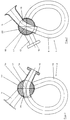
- either the transverse channels 19 and 20 complete the windings 9 to 12 of the suction tubes 1 to 4, which are interrupted in the region of the rotary rotary valve 17, or the windings 9 to 12 are bridged by the transverse channel 21, whereby the latter is illustrated in FIGS. 4 to 6.
- the two possible positions of the rotary rotary valve 17 are adjusted by axial displacement relative to the suction pipes 1 to 4. If the rotary rotary valve 17 is in the extreme right position (FIGS. 1 to 3), combustion air can flow from the intake ports 5 to 8 via the transverse channels 19, the windings 9 to 12 and the transverse channels 20 into the end pieces 13, 14.
- a large intake pipe length is effective in terms of gas dynamics.
- the cross-section of the suction pipes 1 to 4 can be changed by rotating the rotary slide valve 17 about its cylinder axis 18, since the position of the transverse channels 19 and 21 to the intake ports 5 to 8 and the position of the transverse channels 20 and 21 to the end pieces 13 , 14 changed.
- the minimum intake pipe cross section can be set to the value 0 up to complete throttling (FIG. 6), the transverse channels 19 to 21 then being closed by a rotary valve housing 22.
- the exact position of the rotary rotary valve 17 can be preselected via adjusting means 23 in a manner known per se.
- the rotary roller valve 17 can be rotated mechanically, which takes place depending on the position of an accelerator pedal.
- a cable can be provided between the accelerator pedal and the shaft 24.
- the means for the two-stage change in the length of the intake manifold and the throttle element for air volume control are structurally combined in the rotary slide valve 17.
- the air supply to the internal combustion engine takes place under optimal conditions with a very good efficiency.
- the system described can also be used if the intake air (in the case of a different design of a rotary rotary valve) is guided axially through the rotary valve, ie it acts as an air collecting duct. If the rotary rotary valve is arranged centrally in the windings of the suction pipes and forms an inner wall thereof, the intake manifold length can be varied continuously by rotating the rotary valve. At the same time, however, throttling of the internal combustion engine can also take place by axially displacing the roller rotary valve.
- FIGS. 7 and 8 Another embodiment of the invention is shown schematically in FIGS. 7 and 8.
- a suction pipe 25 is shown here, a roller rotary slide valve 26 likewise being arranged in the region of intersection of a turn 27 of the suction pipe 25, as in the first exemplary embodiment.
- a cylinder axis 28 is approximately perpendicular to the plane formed by the winding 27.
- the rotary rotary valve 26 has two transverse channels 29, 30 for each suction pipe 25, the transverse channel 30 being branched. In the position of the rotary rotary valve 26 shown in FIG. 7, the winding 27 is switched between an intake port 31 and an end piece 32 of the intake pipe 25. This means that a large intake manifold length (lower speed range) is effective.
- a branch 33 is connected to the intake port 31 and the winding 27 is bridged by the transverse channel 30.
- a short intake manifold length has a gas dynamic effect (upper speed range).
- the transverse channel 29 is closed by a rotary valve housing 34.
- the length of the intake manifold is adjusted by rotating the rotary rotary valve 26 about its cylinder axis 28. Throttling of the internal combustion engine is to be carried out by axially displacing the rotary rotary valve 26, the effective cross section of the transverse channels 29, 30 changing.
- the adjustment means for this can be designed in a manner comparable to the first embodiment.
Landscapes
- Engineering & Computer Science (AREA)
- Chemical & Material Sciences (AREA)
- Combustion & Propulsion (AREA)
- Mechanical Engineering (AREA)
- General Engineering & Computer Science (AREA)
- Characterised By The Charging Evacuation (AREA)
Applications Claiming Priority (2)
| Application Number | Priority Date | Filing Date | Title |
|---|---|---|---|
| DE4333053 | 1993-09-29 | ||
| DE4333053A DE4333053A1 (de) | 1993-09-29 | 1993-09-29 | Brennkraftmaschine mit einem Luftansaugsystem |
Publications (2)
| Publication Number | Publication Date |
|---|---|
| EP0645530A1 true EP0645530A1 (fr) | 1995-03-29 |
| EP0645530B1 EP0645530B1 (fr) | 1997-05-14 |
Family
ID=6498883
Family Applications (1)
| Application Number | Title | Priority Date | Filing Date |
|---|---|---|---|
| EP94114493A Expired - Lifetime EP0645530B1 (fr) | 1993-09-29 | 1994-09-15 | Moteur à combustion interne avec système d'admission d'air |
Country Status (3)
| Country | Link |
|---|---|
| US (1) | US5438964A (fr) |
| EP (1) | EP0645530B1 (fr) |
| DE (2) | DE4333053A1 (fr) |
Cited By (4)
| Publication number | Priority date | Publication date | Assignee | Title |
|---|---|---|---|---|
| EP0741243A3 (fr) * | 1995-05-04 | 1997-09-17 | Ford Motor Co | Système d'admission pour moteur à combustion interne |
| EP0822325A2 (fr) | 1996-08-02 | 1998-02-04 | Audi Ag | Dispositif de commande de la section d'aspiration de conduits d'admission d'air de moteurs à combustion |
| WO1998032958A1 (fr) * | 1997-01-24 | 1998-07-30 | Filterwerk Mann+Hummel Gmbh | Procede de regulation de la consommation d'air dans le systeme d'aspiration d'un moteur a combustion interne et tubulure d'aspiration pour mettre en oeuvre le procede |
| WO2001064748A1 (fr) * | 2000-03-02 | 2001-09-07 | Protease Ab | Anticorps liant l'acide gamma-carboxyglutamique affichant un epitope |
Families Citing this family (18)
| Publication number | Priority date | Publication date | Assignee | Title |
|---|---|---|---|---|
| BR9709517A (pt) * | 1996-06-03 | 1999-08-10 | Mann & Hummel Filter | Dispositivo de admissão de ar |
| US5967108A (en) | 1996-09-11 | 1999-10-19 | Kutlucinar; Iskender | Rotary valve system |
| JP3558792B2 (ja) * | 1996-09-13 | 2004-08-25 | 愛三工業株式会社 | インテークマニホールドと吸気制御装置及びその製造方法 |
| US5704328A (en) * | 1996-10-02 | 1998-01-06 | Chrysler Corporation | Method to control a short runner bypass valve in the intake manifold of an internal combustion engine |
| JP3248439B2 (ja) * | 1996-12-13 | 2002-01-21 | 三菱自動車工業株式会社 | 筒内噴射型内燃機関の制御装置 |
| JP3250475B2 (ja) * | 1996-12-13 | 2002-01-28 | 三菱自動車工業株式会社 | 筒内噴射型内燃機関の制御装置 |
| DE19712680A1 (de) * | 1997-03-26 | 1998-10-01 | Mann & Hummel Filter | Schaltwalze, insbesondere zur Verwendung in einer Saugrohranlage für eine Mehrzylinder-Brennkraftmaschine |
| DE19738619C2 (de) * | 1997-09-04 | 1999-09-23 | Daimler Chrysler Ag | Saugrohranlage für eine Mehrzylinder-Brennkraftmaschine |
| DE19944108A1 (de) * | 1999-09-15 | 2001-03-22 | Mann & Hummel Filter | Schaltwalze |
| US6295960B1 (en) | 2000-01-12 | 2001-10-02 | Ford Global Technologies, Inc. | Intake manifold communication valve |
| US6382162B2 (en) * | 2000-01-31 | 2002-05-07 | Honda Giken Kogyo Kabushiki Kaisha | Variable intake apparatus for in-line four-cylinder internal combustion engine |
| DE10213334A1 (de) * | 2002-03-25 | 2003-10-09 | Bastra Dipl Ing Otten Gmbh & C | Verbrennungsmotor |
| AU2003246496A1 (en) | 2002-07-19 | 2004-02-09 | Litens Automotive | Intake manifold having variable cross-sectional area |
| US7073473B2 (en) * | 2003-07-18 | 2006-07-11 | Litens Automotive Partnership | Intake manifold variable runner area |
| US6986333B2 (en) * | 2004-05-25 | 2006-01-17 | Litens Automotive | Intake manifold with variable runner area |
| US7347045B2 (en) * | 2004-06-30 | 2008-03-25 | Harley-Davidson Motor Company Group, Inc. | Motorcycle dynamic exhaust system |
| DE102005001862A1 (de) | 2005-01-14 | 2006-07-20 | Dr.Ing.H.C. F. Porsche Ag | Schaltbare Luftansauganlage für eine mehrzylindrige Brennkraftmaschine |
| US7401590B2 (en) * | 2006-10-09 | 2008-07-22 | Harley-Davidson Motor Company Group, Inc. | Active air intake for an engine |
Citations (4)
| Publication number | Priority date | Publication date | Assignee | Title |
|---|---|---|---|---|
| DE3814836A1 (de) * | 1987-05-26 | 1988-12-08 | Volkswagen Ag | Laengenveraenderbares saugrohr fuer eine brennkraftmaschine |
| DE3807193A1 (de) * | 1988-03-04 | 1989-06-01 | Bayerische Motoren Werke Ag | Ansaugvorrichtung fuer eine brennkraftmaschine |
| EP0355960A2 (fr) * | 1988-08-16 | 1990-02-28 | Rover Group Limited | Collecteur d'admission pour moteurs à combustion interne |
| DE3940486A1 (de) * | 1989-12-07 | 1991-06-13 | Audi Ag | Resonanz-ansaugsystem fuer eine mehrzylinder-brennkraftmaschine |
Family Cites Families (10)
| Publication number | Priority date | Publication date | Assignee | Title |
|---|---|---|---|---|
| DE957802C (de) * | 1954-05-07 | 1957-02-07 | Daimler Benz Ag | Ansaugleitung von Brennkraftmaschinen |
| US4664076A (en) * | 1984-06-15 | 1987-05-12 | Honda Giken Kogyo Kabushiki Kaisha | Intake system for internal combustion engine |
| US4679531A (en) * | 1984-11-08 | 1987-07-14 | Mazda Motor Corporation | Intake system for internal combustion engine |
| US4765286A (en) * | 1986-10-16 | 1988-08-23 | Chrysler Motors Corporation | Selectively tuned intake manifold |
| IT1217060B (it) * | 1987-04-30 | 1990-03-14 | Montagni Alviero | Dispositivo di distribuzione per macchine volumetriche alternative, come motori alternativi endotermici con valvola ruotante a forma di solido di rivoluzione in specie sferica. |
| DE3825000A1 (de) * | 1987-07-24 | 1989-02-02 | Avl Verbrennungskraft Messtech | Ansaugleitung von brennkraftmaschinen |
| DE3921081A1 (de) * | 1989-06-28 | 1991-01-10 | Audi Ag | Saugrohranlage fuer eine mehrzylinder-brennkraftmaschine |
| GB2239048B (en) * | 1989-12-12 | 1993-09-29 | Rover Group | An internal combustion engine inlet manifold |
| DE4028489B4 (de) * | 1990-09-07 | 2005-06-23 | Adam Opel Ag | Luftangsaugeinrichtung für eine Brennkraftmaschine |
| US5105784A (en) * | 1991-04-08 | 1992-04-21 | General Motors Corporation | Rotary valve and system for duration and phase control |
-
1993
- 1993-09-29 DE DE4333053A patent/DE4333053A1/de not_active Withdrawn
-
1994
- 1994-09-15 DE DE59402732T patent/DE59402732D1/de not_active Expired - Lifetime
- 1994-09-15 EP EP94114493A patent/EP0645530B1/fr not_active Expired - Lifetime
- 1994-09-26 US US08/311,978 patent/US5438964A/en not_active Expired - Fee Related
Patent Citations (4)
| Publication number | Priority date | Publication date | Assignee | Title |
|---|---|---|---|---|
| DE3814836A1 (de) * | 1987-05-26 | 1988-12-08 | Volkswagen Ag | Laengenveraenderbares saugrohr fuer eine brennkraftmaschine |
| DE3807193A1 (de) * | 1988-03-04 | 1989-06-01 | Bayerische Motoren Werke Ag | Ansaugvorrichtung fuer eine brennkraftmaschine |
| EP0355960A2 (fr) * | 1988-08-16 | 1990-02-28 | Rover Group Limited | Collecteur d'admission pour moteurs à combustion interne |
| DE3940486A1 (de) * | 1989-12-07 | 1991-06-13 | Audi Ag | Resonanz-ansaugsystem fuer eine mehrzylinder-brennkraftmaschine |
Cited By (5)
| Publication number | Priority date | Publication date | Assignee | Title |
|---|---|---|---|---|
| EP0741243A3 (fr) * | 1995-05-04 | 1997-09-17 | Ford Motor Co | Système d'admission pour moteur à combustion interne |
| EP0822325A2 (fr) | 1996-08-02 | 1998-02-04 | Audi Ag | Dispositif de commande de la section d'aspiration de conduits d'admission d'air de moteurs à combustion |
| EP0822325A3 (fr) * | 1996-08-02 | 1998-05-20 | Audi Ag | Dispositif de commande de la section d'aspiration de conduits d'admission d'air de moteurs à combustion |
| WO1998032958A1 (fr) * | 1997-01-24 | 1998-07-30 | Filterwerk Mann+Hummel Gmbh | Procede de regulation de la consommation d'air dans le systeme d'aspiration d'un moteur a combustion interne et tubulure d'aspiration pour mettre en oeuvre le procede |
| WO2001064748A1 (fr) * | 2000-03-02 | 2001-09-07 | Protease Ab | Anticorps liant l'acide gamma-carboxyglutamique affichant un epitope |
Also Published As
| Publication number | Publication date |
|---|---|
| DE4333053A1 (de) | 1995-03-30 |
| EP0645530B1 (fr) | 1997-05-14 |
| DE59402732D1 (de) | 1997-06-19 |
| US5438964A (en) | 1995-08-08 |
Similar Documents
| Publication | Publication Date | Title |
|---|---|---|
| EP0645530B1 (fr) | Moteur à combustion interne avec système d'admission d'air | |
| EP0177794B1 (fr) | Dispositif d'admission pour moteurs polycylindriques | |
| DE3903492B4 (de) | Abgassystem für Mehrzylinder-Verbrennungsmotoren | |
| DE10212596B4 (de) | Variable Einlassvorrichtung für einen Mehrzylinderverbrennungsmotor | |
| DE3433653A1 (de) | Vorrichtung zur aenderung der wirksamen laenge des luftansaugrohres einer verbrennungskraftmaschine | |
| DE3446377A1 (de) | Ansaugvorrichtung fuer kolben-verbrennungskraftmaschinen | |
| EP2017457A2 (fr) | Dispositif de recirculation des gaz d'échappement pour un moteur à combustion interne | |
| EP0480393B1 (fr) | Moteur à combustion avec une vanne cylindrique | |
| DE4117466A1 (de) | Ansaugsystem fuer eine mehrzylinder-brennkraftmaschine | |
| EP0237755A2 (fr) | Dispositif pour le changement continu de la longueur d'un tube d'aspiration d'air d'un moteur à combustion interne | |
| DE3940486A1 (de) | Resonanz-ansaugsystem fuer eine mehrzylinder-brennkraftmaschine | |
| DE102005031393B4 (de) | Variabler Einlasskrümmer mit einem Steuerventil zur Resonanzabstimmung in drei Betriebsarten | |
| EP0490104B1 (fr) | Procédé pour contrôler l'admission d'air pour moteur à combustion interne | |
| EP0778919B1 (fr) | Dispositif variable d'aspiration d'air | |
| DE4034341C2 (de) | Verfahren und Einrichtung zum Betreiben einer gasdynamischen Druckwellenmaschine | |
| DE4041786C2 (de) | Für eine Brennkraftmaschine bestimmte Ansauganlage | |
| DE3701659A1 (de) | Einlasssystem fuer verbrennungsmotoren | |
| EP0954686A1 (fr) | Procede de regulation de la consommation d'air dans le systeme d'aspiration d'un moteur a combustion interne et tubulure d'aspiration pour mettre en oeuvre le procede | |
| DE69300677T2 (de) | Einlasssystem für Brennkraftmaschinen. | |
| DE10332640B3 (de) | Luftansaugkanalsystem für Verbrennungskraftmaschinen | |
| DE60128193T2 (de) | Luftansaugkanalsystem für eine Brennkraftmaschine | |
| DE19506306A1 (de) | Ansaugvorrichtung für eine Kolbenbrennkraftmaschine | |
| DE3804333C2 (de) | Vorrichtung zur Veränderung des Steuerwinkels zwischen einem Maschinenteil und einer dieses betätigenden Antriebseinheit | |
| EP0626509B1 (fr) | Moteur à combustion interne avec un conduit d'admission double d'un gas à introduire dans un cylindre | |
| DE19820245A1 (de) | Ansaugsystem für eine Brennkraftmaschine |
Legal Events
| Date | Code | Title | Description |
|---|---|---|---|
| PUAI | Public reference made under article 153(3) epc to a published international application that has entered the european phase |
Free format text: ORIGINAL CODE: 0009012 |
|
| AK | Designated contracting states |
Kind code of ref document: A1 Designated state(s): DE FR GB SE |
|
| 17P | Request for examination filed |
Effective date: 19950411 |
|
| 17Q | First examination report despatched |
Effective date: 19960528 |
|
| GRAG | Despatch of communication of intention to grant |
Free format text: ORIGINAL CODE: EPIDOS AGRA |
|
| GRAH | Despatch of communication of intention to grant a patent |
Free format text: ORIGINAL CODE: EPIDOS IGRA |
|
| GRAH | Despatch of communication of intention to grant a patent |
Free format text: ORIGINAL CODE: EPIDOS IGRA |
|
| GRAA | (expected) grant |
Free format text: ORIGINAL CODE: 0009210 |
|
| AK | Designated contracting states |
Kind code of ref document: B1 Designated state(s): DE FR GB SE |
|
| REF | Corresponds to: |
Ref document number: 59402732 Country of ref document: DE Date of ref document: 19970619 |
|
| PG25 | Lapsed in a contracting state [announced via postgrant information from national office to epo] |
Ref country code: SE Effective date: 19970814 |
|
| ET | Fr: translation filed | ||
| GBT | Gb: translation of ep patent filed (gb section 77(6)(a)/1977) |
Effective date: 19970929 |
|
| PLBE | No opposition filed within time limit |
Free format text: ORIGINAL CODE: 0009261 |
|
| STAA | Information on the status of an ep patent application or granted ep patent |
Free format text: STATUS: NO OPPOSITION FILED WITHIN TIME LIMIT |
|
| 26N | No opposition filed | ||
| REG | Reference to a national code |
Ref country code: GB Ref legal event code: IF02 |
|
| REG | Reference to a national code |
Ref country code: GB Ref legal event code: 732E Free format text: REGISTERED BETWEEN 20090219 AND 20090225 |
|
| REG | Reference to a national code |
Ref country code: GB Ref legal event code: 732E Free format text: REGISTERED BETWEEN 20090305 AND 20090311 |
|
| REG | Reference to a national code |
Ref country code: GB Ref legal event code: 732E Free format text: REGISTERED BETWEEN 20091105 AND 20091111 |
|
| REG | Reference to a national code |
Ref country code: GB Ref legal event code: 732E Free format text: REGISTERED BETWEEN 20091112 AND 20091118 |
|
| REG | Reference to a national code |
Ref country code: DE Ref legal event code: R081 Ref document number: 59402732 Country of ref document: DE Owner name: GM GLOBAL TECHNOLOGY OPERATIONS LLC (N. D. GES, US Free format text: FORMER OWNER: GM GLOBAL TECHNOLOGY OPERATIONS, INC., DETROIT, MICH., US Effective date: 20110323 Ref country code: DE Ref legal event code: R081 Ref document number: 59402732 Country of ref document: DE Owner name: GM GLOBAL TECHNOLOGY OPERATIONS LLC (N. D. GES, US Free format text: FORMER OWNER: GM GLOBAL TECHNOLOGY OPERATIONS, INC., DETROIT, US Effective date: 20110323 |
|
| PGFP | Annual fee paid to national office [announced via postgrant information from national office to epo] |
Ref country code: GB Payment date: 20120912 Year of fee payment: 19 |
|
| PGFP | Annual fee paid to national office [announced via postgrant information from national office to epo] |
Ref country code: FR Payment date: 20120926 Year of fee payment: 19 Ref country code: DE Payment date: 20120912 Year of fee payment: 19 |
|
| GBPC | Gb: european patent ceased through non-payment of renewal fee |
Effective date: 20130915 |
|
| REG | Reference to a national code |
Ref country code: DE Ref legal event code: R119 Ref document number: 59402732 Country of ref document: DE Effective date: 20140401 |
|
| REG | Reference to a national code |
Ref country code: FR Ref legal event code: ST Effective date: 20140530 |
|
| PG25 | Lapsed in a contracting state [announced via postgrant information from national office to epo] |
Ref country code: GB Free format text: LAPSE BECAUSE OF NON-PAYMENT OF DUE FEES Effective date: 20130915 |
|
| PG25 | Lapsed in a contracting state [announced via postgrant information from national office to epo] |
Ref country code: FR Free format text: LAPSE BECAUSE OF NON-PAYMENT OF DUE FEES Effective date: 20130930 Ref country code: DE Free format text: LAPSE BECAUSE OF NON-PAYMENT OF DUE FEES Effective date: 20140401 |