EP0645560A1 - Dispositif de commande pour transmission automatique - Google Patents
Dispositif de commande pour transmission automatique Download PDFInfo
- Publication number
- EP0645560A1 EP0645560A1 EP94115150A EP94115150A EP0645560A1 EP 0645560 A1 EP0645560 A1 EP 0645560A1 EP 94115150 A EP94115150 A EP 94115150A EP 94115150 A EP94115150 A EP 94115150A EP 0645560 A1 EP0645560 A1 EP 0645560A1
- Authority
- EP
- European Patent Office
- Prior art keywords
- gear change
- oil
- hydraulic servo
- supplying circuit
- valve
- Prior art date
- Legal status (The legal status is an assumption and is not a legal conclusion. Google has not performed a legal analysis and makes no representation as to the accuracy of the status listed.)
- Granted
Links
- 230000005540 biological transmission Effects 0.000 title claims abstract description 34
- 230000008859 change Effects 0.000 claims abstract description 256
- 238000000034 method Methods 0.000 description 30
- 230000008569 process Effects 0.000 description 30
- 238000010586 diagram Methods 0.000 description 8
- 230000008878 coupling Effects 0.000 description 5
- 238000010168 coupling process Methods 0.000 description 5
- 238000005859 coupling reaction Methods 0.000 description 5
- 238000001514 detection method Methods 0.000 description 4
- 230000001052 transient effect Effects 0.000 description 3
- 230000004048 modification Effects 0.000 description 2
- 238000012986 modification Methods 0.000 description 2
- 101150016164 msw1 gene Proteins 0.000 description 2
- 230000007935 neutral effect Effects 0.000 description 2
- 230000035939 shock Effects 0.000 description 2
Images


Classifications
-
- F—MECHANICAL ENGINEERING; LIGHTING; HEATING; WEAPONS; BLASTING
- F16—ENGINEERING ELEMENTS AND UNITS; GENERAL MEASURES FOR PRODUCING AND MAINTAINING EFFECTIVE FUNCTIONING OF MACHINES OR INSTALLATIONS; THERMAL INSULATION IN GENERAL
- F16H—GEARING
- F16H61/00—Control functions within control units of change-speed- or reversing-gearings for conveying rotary motion ; Control of exclusively fluid gearing, friction gearing, gearings with endless flexible members or other particular types of gearing
- F16H61/04—Smoothing ratio shift
- F16H61/06—Smoothing ratio shift by controlling rate of change of fluid pressure
- F16H61/061—Smoothing ratio shift by controlling rate of change of fluid pressure using electric control means
-
- F—MECHANICAL ENGINEERING; LIGHTING; HEATING; WEAPONS; BLASTING
- F16—ENGINEERING ELEMENTS AND UNITS; GENERAL MEASURES FOR PRODUCING AND MAINTAINING EFFECTIVE FUNCTIONING OF MACHINES OR INSTALLATIONS; THERMAL INSULATION IN GENERAL
- F16H—GEARING
- F16H61/00—Control functions within control units of change-speed- or reversing-gearings for conveying rotary motion ; Control of exclusively fluid gearing, friction gearing, gearings with endless flexible members or other particular types of gearing
- F16H61/04—Smoothing ratio shift
- F16H2061/0444—Smoothing ratio shift during fast shifting over two gearsteps, e.g. jumping from fourth to second gear
-
- F—MECHANICAL ENGINEERING; LIGHTING; HEATING; WEAPONS; BLASTING
- F16—ENGINEERING ELEMENTS AND UNITS; GENERAL MEASURES FOR PRODUCING AND MAINTAINING EFFECTIVE FUNCTIONING OF MACHINES OR INSTALLATIONS; THERMAL INSULATION IN GENERAL
- F16H—GEARING
- F16H61/00—Control functions within control units of change-speed- or reversing-gearings for conveying rotary motion ; Control of exclusively fluid gearing, friction gearing, gearings with endless flexible members or other particular types of gearing
- F16H61/04—Smoothing ratio shift
- F16H61/08—Timing control
Definitions
- the present invention relates to a controller of an automatic transmission.
- P (parking ) range, R (reverse) range, N (neutral) range, D (drive) range, 2 (second) range and L (low) range are provided for an automatic transmission and a gear change step is automatically selected and a gear change is made corresponding to a traveling condition of a vehicle as a driver selects a range by moving a shift lever to its range position in an I shaped pattern.
- H pattern shift positions arranged in H shape similarly to a manual shift, in addition to the I pattern range positions, to allow to move a shift lever to a range position to select to travel in an automatic gear change mode and to move the shift lever to a shift position to select to travel in a manual gear change mode (See Japanese Patent Laid-Open No. Hei 3-199758). It allows a driver to freely select the gear change steps and to obtain a sufficient shift feeling.
- a jumped gear change (e.g. 1-3 gear change, 1-4 gear change, etc.) is sometimes made depending on a traveling condition of the vehicle. Further, in the automatic transmission having the I pattern range positions and H pattern shift positions, a jumped gear change is sometimes made by manipulating the shift lever for example while driving the vehicle in the manual gear change mode.
- the targeted gear change step a thermal load of the frictional engage elements engaged during the gear change becomes great when the gear change is made directly to the targeted gear change step and hence the durability of the frictional engage elements is lowered.
- the thermal load of the frictional engage elements is reduced by making a gear change once to a gear change step between the current gear change step and the targeted gear change step (hereinafter referred to as "the intermediate gear change step") when a jumped gear change is to be made.
- a gear change to the targeted gear change step is made after firmly making the gear change to the intermediate gear change step by switching to a solenoid valve for the gear change to the targeted gear change step when a ratio of input number of revolutions and output number of revolutions reaches to a preset value in order to suppress a gear change shock from occurring (See Japanese Patent Laid-Open No. Hei 1-188750).
- the frictional engage elements for making the gear change to the intermediate gear change step and the frictional engage elements for making the gear change to the targeted gear change step are engaged by supplying oil to the hydraulic servos and the hydraulic pressure is raised by adjusting by an accumulator, so that it takes a considerable time to raise the hydraulic pressure to the state in which the frictional engage elements can be engaged.
- the gear change time a time for making the gear change (hereinafter referred to as "the gear change time"), but also gives a sense of incompatibility to the driver.
- a controller of an automatic transmission of the present invention comprises a first hydraulic servo to which oil is supplied to make a jumped gear change from a current gear change step to a targeted gear change step, a second hydraulic servo to which oil is supplied to make a gear change from the current gear change step to an intermediate gear change step, a limited oil supplying circuit created going through oil amount limiting means, a quick oil supplying circuit created without going through the oil amount limiting means and pressure governing means for governing a line pressure under a controlled pressure to supply oil under the controlled pressure to the quick oil supplying circuit.
- oil path switching means for switching the limited oil supplying circuit and the quick oil supplying circuit to supply oil to the first hydraulic servo or the second hydraulic servo.
- the operating pressure can be quickly increased by supplying oil to the second hydraulic servo via the quick oil supplying circuit, the durability of the frictional engage elements may be improved, the gear change time may be shortened even when the jumped gear change is made via the intermediate gear change step and no sense of incompatibility is given to the driver.
- the operating pressure in the transient state may be accurately controlled.
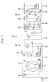
- Fig. 2 is a schematic diagram of an automatic transmission according to the embodiment of the present invention
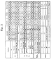
- Fig. 3 is a table showing operations of the automatic transmission according to the embodiment of the present invention.
- the automatic transmission comprises a transmission (T/M) 10 and a torque converter 11, wherein revolutions generated by an engine (not shown) are transmitted to the transmission 10.
- the transmission 10 changes their speed and transmits them to driving wheels (not shown).
- the torque converter 11 comprises a pump impeller 12, turbine runner 13 and stator 14 as well as a lock-up clutch 15 for improving a power transmission efficiency and transmits revolutions of an input member 16 which is an output shaft of the engine to an input shaft 17 of the transmission 10 indirectly by a flow of oil within the torque converter 11 or directly by locking the lock-up clutch 15.
- the transmission 10 comprises a sub-gear change unit 18 and main gear change unit 19.
- the sub-gear change unit 18 has an overdrive planetary gear unit 20 and the main gear change unit 19 has a front planetary gear unit 21 and rear planetary gear unit 22.
- the overdrive planetary gear unit 20 comprises a carrier CR1 connected to the input shaft 17 and supporting a pinion P1, sun gear S1 surrounding the input shaft 17 and ring gear R1 linked to an input shaft 23 of the main gear change unit 19.
- the carrier CR1 and the sun gear S1 are linked through the intermediary of a third clutch C0 and third one-way clutch F0 and the sun gear S1 and a case 24 are linked through the intermediary of a fourth brake B0.
- the front planetary gear unit 21 comprises a carrier CR2 connected to an output shaft 25 and supporting a pinion P2, sun gear S2 surrounding the output shaft 25 and is integrated with a sun gear S3 of the rear planetary gear unit 22 and ring gear R2 linked to the input shaft 23 through the intermediary of a first clutch C1.
- the input shaft 23 and the sun gear S2 are linked through the intermediary of a second clutch C2 and the sun gear S2 and the case 24 are linked through the intermediary of a first brake B1 composed of a band brake.
- the sun gear S2 and the case 24 are further linked through the intermediary of a first one-way clutch F1 and second brake B2.
- the rear planetary gear unit 22 comprises a carrier CR3 supporting a pinion P3, sun gear S3 and ring gear R3 integral with the input shaft 25.
- the carrier CR3 and the case 24 are linked through the intermediary of a third brake B3 and second one-way clutch F2 provided in parallel.
- Solenoid valves S1 through S4, linear solenoid valves SLU and SLN, first clutch C1, second clutch C2, third clutch C0, first brake B1, second brake B2, third brake B3, fourth brake B0, first one-way clutch F1, second one-way clutch F2 and third one-way clutch F0 in the aforementioned automatic transmission are controlled as shown in Fig. 3 in each gear change step of the P-range, R-range, D-range, 2-range and L-range, respectively.
- a discrimination speed for prohibiting from driving in the R-range is set at 20 [km/h].
- each of the solenoid valves S1 through S4 in the N-range is controlled corresponding to a car speed and follows a solenoid pattern in the D-range. Further, for item *3, the third clutch C0 is engaged in the first to third speed and for item *4, the fourth brake B0 is engaged in the fourth speed.
- the first clutch C1 and third clutch C0 are engaged and the second one-way clutch F2 and third one-way clutch F0 are put into a locked state. Therefore, in the overdrive planetary gear unit 20, a direct coupling state is created through the intermediary of the third clutch C0 and third one-way clutch F0 and the revolution of the input shaft 17 is transmitted to the main gear change unit 19 as it is. Further, in the main gear change unit 19, the revolution of the input shaft 23 is transmitted to the ring gear R2 of the front planetary gear unit 21 through the intermediary of the first clutch C1, to the carrier CR2 and to the output shaft 25 which is integral with the carrier CR2.
- the first clutch C1, third clutch C0 and second brake B2 are engaged and the first one-way clutch F1 and third one-way clutch F0 are put into a locked state. Therefore, in the overdrive planetary gear unit 20, the direct coupling state is maintained and the revolution of the input shaft 17 is transmitted to the input shaft 23 of the main gear change unit 19 as it is. In the main gear change unit 19, the revolution of the input shaft 23 is transmitted to the ring gear R2 of the front planetary gear unit 21 through the intermediary of the first clutch C1.
- the first clutch C1, second clutch C2, third clutch C0 and second brake B2 are engaged and the third one-way clutch F1 is put into a locked state. Therefore, in the overdrive planetary gear unit 20, the direct coupling state is maintained and the revolution of the input shaft 17 is transmitted to the input shaft 23 of the main gear change unit 19 as it is. In the main gear change unit 19, the front planetary gear unit 21 is put into a direct coupling state as the first clutch C1 and second clutch C2 are engaged and the revolution of the input shaft 23 is transmitted to the output shaft 25 as it is.
- the first clutch C1, second clutch C2, second brake B2 and fourth brake B0 are engaged.
- the third clutch C0 is released and the fourth brake B0 is engaged.
- the sun gear S1 of the overdrive planetary gear unit 20 is locked by the engagement of the fourth brake B0, the carrier CR1 rotates and transmits the revolution while autorotating the pinion P1 and the revolution of the overdrive is transmitted to the input shaft 23 of the main gear change unit 19 which is in the direct coupling state.
- Fig. 4 is a schematic diagram of the controller of the automatic transmission showing the embodiment of the present invention.
- the reference numeral and character (31) denotes a CPU for controlling the whole controller of the automatic transmission to which a throttle opening theta, output number of revolutions N O , car speed v, input number of revolutions N T , engine speed N E and others are input in a form of detection signal of each, (NSW) a neutral start switch signal, and (MSW) a manual switch signal.
- the CPU 31 controls the solenoid valves S1 through S4 and linear solenoid valve SLN, etc.
- the solenoid valve S1 switches a 2-3 shift valve (not shown)
- solenoid valve S2 switches a 1-2 shift valve and 3-4 shift valve (not shown)
- solenoid valve S3 switches a B-1 timing valve (not shown)
- solenoid valve S4 switches an engine brake control valve (not shown).
- the linear solenoid valve SLN governs a pressure control valve (not shown).
- the CPU 31 discriminates a traveling pattern of the vehicle based on each detection signal, controls the linear solenoid valve SLN per each traveling pattern and controls a pressure of oil supplied to hydraulic servos (not shown) to engage the frictional engage elements (not shown) (hereinafter referred to as "the operating pressure").
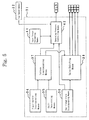
- Fig. 5 is a block diagram of the controller of the automatic transmission showing the embodiment of the present invention.
- a car speed sensor 32 detects the car speed v
- power on/off discriminating means 34 discriminates whether the vehicle is in a power-on state.
- the power on/off discriminating means 34 discriminates whether an accel pedal (not shown) is being stepped on or not and determines that the vehicle is in the power-on state when the pedal is being stepped on and that the vehicle is power-off state when the pedal is not being stepped on.
- Shift determining means 35 determines whether an up-shift gear change or down-shift gear change is to be made and whether a gear change to an intermediate gear change step is to be made or not in making the up-shift gear change
- gear change state discriminating means 36 discriminates whether the gear change to the intermediate gear change step is about to be finished or not
- pattern determining means 37 determines a gear change pattern of the vehicle based on the discrimination result obtained by the power on/off discriminating means 34 and the determination result obtained by the shift determining means 35
- valve switching means 38 controls the solenoid valves S1 through S4 based on the discrimination result obtained by the gear change state discriminating means 36 and on the determination result made by the gear change state discriminating means 36
- input torque estimating means 41 estimates an input torque and operating pressure control means 42 controls the linear solenoid valve SLN based on the discrimination result obtained by the gear change state discriminating means 36, the determination result obtained by the pattern determining means 37 and the estimation result obtained by the input torque estimating means 41.
- Fig. 6 is a main flowchart showing the quick control operation of the controller of the automatic transmission according to the embodiment of the present invention.
- Fig. 7 is a flowchart of the subroutine of the power on/off discriminating process in the embodiment of the present invention.
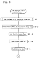
- Fig. 8 is a first flowchart of the subroutine of the shift determining process in the embodiment of the present invention
- Fig. 9 is a second flowchart of the subroutine of the shift determining process in the embodiment of the present invention
- Fig. 10 is a graph showing a first example of a limitation map in the embodiment of the present invention
- Fig. 11 is a graph showing a second example of the limitation map in the embodiment of the present invention.
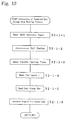
- Fig. 12 is a flowchart of the subroutine of the targeted gear change step reading process in the embodiment of the present invention
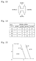
- Fig. 13 is a drawing illustrating a manual switch in the embodiment of the present invention
- Fig. 14 is a table for discriminating shift positions in the embodiment of the present invention
- Fig. 15 is a gear change map according to the embodiment of the present invention.
- Fig. 16 is a flowchart of the subroutine of the pattern discriminating process according to the embodiment of the present invention.
- the discrimination is made whether the gear change pattern of the vehicle is the down-shift gear change or up-shift gear change and when it is the up-shift gear change, whether it is the gear change to the targeted gear change step or the gear change to the intermediate gear change step.
- Fig. 1 is a diagram illustrating a hydraulic circuit according to the embodiment of the present invention.
- the reference numeral and character (P L ) denotes a line pressure, (P D ) a D-range pressure, (51) a 1-2 shift valve for making a 1-2 gear change, (52) a 2-3 shift valve for making a 2-3 gear change, (53) a 3-4 shift valve for making a 3-4 gear change, (55) a pressure control valve, (57) an engine brake control valve and (59) a B-1 timing valve.
- the reference numeral (B-1) denotes a hydraulic servo of the first brake B1 (Fig. 2), (B-2) a hydraulic servo of the second brake B2, (B-3) a hydraulic servo of the third brake B3, (B-0) a hydraulic servo of the fourth brake B0, (C-2) a hydraulic servo of the second clutch C2 and (C-0) a hydraulic servo of the third clutch C0.
- the hydraulic servo B-2 is supplied with oil via an orifice valve 61 which operates as oil amount limiting means and an operating pressure of the hydraulic servo B-2 is governed by an accumulator 62 connected via an orifice valve 63.
- the hydraulic servo B-0 is supplied with oil via an orifice valve 65, oil amount limiting means, and an operating pressure of the hydraulic servo B-0 is governed by an accumulator 67 connected via an orifice valve 66.
- the hydraulic servo C-2 is supplied with oil via an orifice valve 70, oil amount limiting means, and an operating pressure of the hydraulic servo C-2 is governed by an accumulator 72 connected via an orifice valve 71.
- an orifice valve 73 is connected to the hydraulic servo C-0, a check valve 75 is connected to the hydraulic servo B-3 and a check valve 76 is connected to the orifice valve 70.
- a solenoid valve S1 switches the 2-3 shift valve 52, a solenoid valve S2 switches the 1-2 shift valve 51 and 3-4 shift valve 53, a solenoid valve S3 switches the B-1 timing valve 59, a solenoid valve S4 switches the engine brake control valve 57 and the linear solenoid valve SLN governs the pressure of the pressure control valve 55.
- each solenoid of the solenoid valves S1 through S4 becomes ON when the 1-2 gear change is made.
- the 1-2 shift valve 51, 2-3 shift valve 52, 3-4 shift valve 53 and engine brake control valve 57 come to the left half position of the drawing (hereinafter referred to as "the left half position") and the B-1 timing valve 59 comes to the right half position of the drawing (hereinafter referred to as the "right half position").
- hydraulic servo B-2 can be supplied with oil by the limited oil supplying circuit created via the orifice valve 61 and a oil path L-1.
- each solenoid of the solenoid valves S1 and S2 turns on and each solenoid of the solenoid valves S3 and S4 turns off.
- the 1-2 shift valve 51, 2-3 shift valve 52, 3-4 shift valve 53 and B-1 timing valve 59 come to the left half position and the engine brake control valve 57 comes to the right half position.
- the pressure of the line pressure P L can be governed by the pressure control valve 55 by operating the the linear solenoid valve SLN.
- the controlled pressure oil under the pressure (hereinafter referred to as "the controlled pressure") is supplied to the hydraulic servo B-2 via the engine brake control valve 57, 1-2 shift valve 51, 2-3 shift valve 52 and B-1 timing valve 59.
- the solenoid of the solenoid valve S1 turns off and each solenoid of the solenoid valves S2 through S4 turns on.
- the 1-2 shift valve 51, 3-4 shift valve 53 and engine brake control valve 57 come to the left half position and the 2-3 shift valve 52 and B-1 timing valve 59 come to the right half position.
- oil under the D-range pressure P D is supplied to the orifice valve 70 via the 1-2 shift valve 51, 2-3 shift valve 52 and check valve 76 and after its pressure is governed by the orifice valve 70, it is supplied to the hydraulic servo C-2.
- the operating pressure of the hydraulic servo C-2 is controlled by the accumulator 72 to which oil is supplied via the orifice valve 71.
- the hydraulic servo C-0 and hydraulic servo B-2 have been supplied with oil from the time of the second speed.
- hydraulic servo C-2 can be supplied with oil by the limited oil supplying circuit created via the orifice valve 70.
- each solenoid of the solenoid valves S1 and S4 turns off and each solenoid of the solenoid valves S2 and S3 turns on.
- the 1-2 shift valve 51 and 3-4 shift valve 53 come to the left half position and the 2-3 shift valve 52, engine brake control valve 57 and B-1 timing valve 59 come to the right half position.
- the pressure of the line pressure P L can be governed by the pressure control valve 55 by operating the linear solenoid valve SLN.
- oil under the controlled pressure is supplied to the hydraulic servo C-2 via the engine brake control valve 57, 1-2 shift valve 51, 2-3 shift valve 52 and 3-4 shift valve 53.
- each solenoid of the solenoid valves S1 and S2 turns off and each solenoid of the solenoid valves S3 and S4 turns on.
- the 1-2 shift valve 51 and engine brake control valve 57 come to the left half position and the 2-3 shift valve 52, 3-4 shift valve 53 and B-1 timing valve 59 come to the right half position.
- hydraulic servo B-2 can be supplied with oil by the limited oil supplying circuit created via the orifice valve 65 and passing through an oil path L-3.
- each solenoid of the solenoid valves S1, S2 and S4 turns off and the solenoid of the solenoid valve S3 turns on.
- the 1-2 shift valve 51 comes to the left half position and the 2-3 shift valve 52, 3-4 shift valve 53, engine brake control valve 57 and B-1 timing valve 59 come to the right half position.
- the pressure of the line pressure P L can be governed by the pressure control valve 55 by operating the the linear solenoid valve SLN.
- oil under the controlled pressure is supplied to the hydraulic servo B-0 via the engine brake control valve 57 and 3-4 shift valve 53.
- oil can be supplied to each of the hydraulic servos B-2, B-0 and C-2 not only by the limited oil supplying circuit created going through the orifice valves 61, 65 and 70 but also by the quick oil supplying circuit created without going through the orifice valves 61, 65 and 70 when the 1-2, 2-3 and 3-4 gear changes are made. Accordingly, it allows to increase the operating pressure of each of the hydraulic servos B-2, B-0 and C-2, to quickly engage the second brake B2, fourth brake B0 and second clutch C2 and thereby to shorten the gear change time. Further, because the operating pressure can be generated directly by the linear solenoid valve SLN, the operating pressure in the transient state may be accurately controlled.
- oil is supplied to each of the hydraulic servos B-2, B-0 and C-2 as the first hydraulic servo via the quick oil supplying circuit to make a gear change to a targeted gear change step and oil is supplied to each of the hydraulic servos B-2, B-0 and C-2 as the second hydraulic servo via the limited oil supplying circuit to make a gear change to an intermediate gear change step.
- the quick oil supplying circuit and limited oil supplying circuit for making the gear change to the targeted gear change step are communicated, oil of the limited oil supplying circuit will not enter the quick oil supplying circuit because a hydraulic pressure within the quick oil supplying circuit is generally higher than that of the limited oil supplying circuit.
- the gear change to the targeted gear change step may be thus made independently from the gear change to the intermediate gear change step, the gear change time to the targeted gear change step may be shortened and the operating pressure in the transient state may be accurately controlled.
- oil is supplied to each of the hydraulic servos B-2, B-0 and C-2 via the quick oil supplying circuit to make the gear change to the intermediate gear change step and the gear change is switched to that to the targeted gear change step immediately before the gear change to the intermediate gear change step ends. Then oil is supplied via the limited oil supplying circuit to each of the hydraulic servos B-2, B-0 and C-2 to which oil has been supplied until immediately before the gear change to the intermediate gear change step has ended and oil is supplied via the quick oil supplying circuit to each of the hydraulic servos B-2, B-0 and C-2 for making the gear change to the targeted gear change step.
- the discrimination number of revolutions N NEXT is set per each intermediate gear change step with the throttle opening theta as a parameter.
- Fig. 17 is a flowchart of the subroutine of the valve switching process, operating pressure controlling process and gear change state discriminating process in the embodiment of the present invention
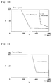
- Fig. 18 is a time chart when a jumped gear change is made in the embodiment of the present invention
- Fig. 19 is a time chart when a jumped gear change is made via an intermediate gear change step in the embodiment of the present invention.
- the reference characters (T O ) denotes an output shaft torque, (N E ) an engine speed, (P B-3 ) an operating pressure of the hydraulic servo B-3 (Fig. 1), (P C-2 ) an operating pressure of the hydraulic servo C-2 and (P B-2 ) an operating pressure of the hydraulic servo B-2.
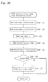
- Fig. 20 is a flowchart of the subroutine of the gear change state discriminating process in the embodiment of the present invention
- Fig. 21 is a graph showing a first example of a determination revolution map according to the embodiment of the present invention
- Fig. 22 is a graph showing a second example of the determination revolution map according to the embodiment of the present invention.
Landscapes
- Engineering & Computer Science (AREA)
- General Engineering & Computer Science (AREA)
- Physics & Mathematics (AREA)
- Fluid Mechanics (AREA)
- Mechanical Engineering (AREA)
- Control Of Transmission Device (AREA)
Applications Claiming Priority (2)
| Application Number | Priority Date | Filing Date | Title |
|---|---|---|---|
| JP24336693A JP3298257B2 (ja) | 1993-09-29 | 1993-09-29 | 自動変速機の制御装置 |
| JP243366/93 | 1993-09-29 |
Publications (2)
| Publication Number | Publication Date |
|---|---|
| EP0645560A1 true EP0645560A1 (fr) | 1995-03-29 |
| EP0645560B1 EP0645560B1 (fr) | 1997-08-06 |
Family
ID=17102774
Family Applications (1)
| Application Number | Title | Priority Date | Filing Date |
|---|---|---|---|
| EP94115150A Expired - Lifetime EP0645560B1 (fr) | 1993-09-29 | 1994-09-26 | Dispositif de commande pour transmission automatique |
Country Status (4)
| Country | Link |
|---|---|
| US (1) | US5573478A (fr) |
| EP (1) | EP0645560B1 (fr) |
| JP (1) | JP3298257B2 (fr) |
| DE (1) | DE69404793T2 (fr) |
Cited By (2)
| Publication number | Priority date | Publication date | Assignee | Title |
|---|---|---|---|---|
| EP0833084A3 (fr) * | 1996-09-25 | 1999-07-21 | Honda Giken Kogyo Kabushiki Kaisha | Dispositif de commande pour transmission véhiculaire à commande hydraulique |
| EP1219868A3 (fr) * | 2000-12-28 | 2007-09-05 | Aisin Aw Co., Ltd. | Dispositif de commande de changement de vitesses pour transmission automatique |
Families Citing this family (11)
| Publication number | Priority date | Publication date | Assignee | Title |
|---|---|---|---|---|
| JPH08303575A (ja) * | 1995-05-10 | 1996-11-19 | Aisin Seiki Co Ltd | 自動変速機 |
| JP3299661B2 (ja) * | 1995-08-10 | 2002-07-08 | 本田技研工業株式会社 | ベルト式無段変速機 |
| JP3331844B2 (ja) * | 1995-12-19 | 2002-10-07 | アイシン・エィ・ダブリュ株式会社 | 自動変速機の油圧制御装置 |
| JP3506852B2 (ja) * | 1996-09-27 | 2004-03-15 | ジヤトコ株式会社 | 自動変速機における変速時間自動調整装置 |
| JP3301344B2 (ja) * | 1997-04-09 | 2002-07-15 | アイシン・エィ・ダブリュ株式会社 | 自動変速機の変速制御装置 |
| JP4626006B2 (ja) * | 2000-03-31 | 2011-02-02 | アイシン精機株式会社 | 自動変速機の油圧制御装置 |
| JP4524917B2 (ja) * | 2000-12-28 | 2010-08-18 | アイシン・エィ・ダブリュ株式会社 | 自動変速機の変速制御装置 |
| JP3839368B2 (ja) * | 2002-06-28 | 2006-11-01 | アイシン・エィ・ダブリュ株式会社 | 自動変速機の油圧制御装置 |
| WO2005119096A2 (fr) | 2004-06-01 | 2005-12-15 | Carne Gary S | Modulation de pression de transmission par clapet a orifice traversant |
| JP4211723B2 (ja) * | 2004-10-14 | 2009-01-21 | トヨタ自動車株式会社 | 自動変速機の油圧制御装置 |
| JP6447579B2 (ja) * | 2016-06-13 | 2019-01-09 | トヨタ自動車株式会社 | 車両の制御装置 |
Citations (5)
| Publication number | Priority date | Publication date | Assignee | Title |
|---|---|---|---|---|
| US4532829A (en) * | 1983-07-29 | 1985-08-06 | Nissan Motor Company, Ltd. | Hydraulic control system for automatic transmission |
| DE4035726A1 (de) * | 1989-11-09 | 1991-05-16 | Aisin Aw Co | Manuelle gangwaehleinrichtung fuer fahrzeug-automatikgetriebe |
| DE4042045A1 (de) * | 1989-12-28 | 1991-07-04 | Aisin Aw Co | Automatikgetriebe fuer fahrzeuge |
| JPH03199758A (ja) * | 1989-12-28 | 1991-08-30 | Aisin Aw Co Ltd | 車両用自動変速機 |
| US5094130A (en) * | 1988-12-26 | 1992-03-10 | Jatco Corporation | Shift control system for automatic power transmission with feature of suppression of shift shock during 4-2 downshift |
Family Cites Families (7)
| Publication number | Priority date | Publication date | Assignee | Title |
|---|---|---|---|---|
| US4722251A (en) * | 1985-07-31 | 1988-02-02 | Aisin-Warner Kabushiki Kaisha | Hydraulic circuit for controlling an automatic transmission |
| JPH0743029B2 (ja) * | 1987-07-02 | 1995-05-15 | 三菱電機株式会社 | 自動変速機の制御装置 |
| EP0354004A3 (fr) * | 1988-08-02 | 1992-03-04 | Toyota Jidosha Kabushiki Kaisha | Commande hydraulique pour transmissions automatiques de véhicule adaptée a engager l'accouplement à des vitesses différentes suivant la puissance de sortie |
| JP2748550B2 (ja) * | 1989-05-18 | 1998-05-06 | 日産自動車株式会社 | 自動変速機のエンジンブレーキ制御装置 |
| DE4235866A1 (de) * | 1991-10-24 | 1993-07-01 | Aisin Aw Co | Steuersystem fuer fahrzeugautomatikgetriebe |
| JP3131302B2 (ja) * | 1992-08-31 | 2001-01-31 | マツダ株式会社 | 自動変速機の変速制御装置 |
| JP3094747B2 (ja) * | 1993-09-29 | 2000-10-03 | アイシン・エィ・ダブリュ株式会社 | 自動変速機の制御装置 |
-
1993
- 1993-09-29 JP JP24336693A patent/JP3298257B2/ja not_active Expired - Fee Related
-
1994
- 1994-09-26 EP EP94115150A patent/EP0645560B1/fr not_active Expired - Lifetime
- 1994-09-26 DE DE69404793T patent/DE69404793T2/de not_active Expired - Fee Related
- 1994-09-29 US US08/315,065 patent/US5573478A/en not_active Expired - Lifetime
Patent Citations (5)
| Publication number | Priority date | Publication date | Assignee | Title |
|---|---|---|---|---|
| US4532829A (en) * | 1983-07-29 | 1985-08-06 | Nissan Motor Company, Ltd. | Hydraulic control system for automatic transmission |
| US5094130A (en) * | 1988-12-26 | 1992-03-10 | Jatco Corporation | Shift control system for automatic power transmission with feature of suppression of shift shock during 4-2 downshift |
| DE4035726A1 (de) * | 1989-11-09 | 1991-05-16 | Aisin Aw Co | Manuelle gangwaehleinrichtung fuer fahrzeug-automatikgetriebe |
| DE4042045A1 (de) * | 1989-12-28 | 1991-07-04 | Aisin Aw Co | Automatikgetriebe fuer fahrzeuge |
| JPH03199758A (ja) * | 1989-12-28 | 1991-08-30 | Aisin Aw Co Ltd | 車両用自動変速機 |
Cited By (3)
| Publication number | Priority date | Publication date | Assignee | Title |
|---|---|---|---|---|
| EP0833084A3 (fr) * | 1996-09-25 | 1999-07-21 | Honda Giken Kogyo Kabushiki Kaisha | Dispositif de commande pour transmission véhiculaire à commande hydraulique |
| EP1302705A1 (fr) * | 1996-09-25 | 2003-04-16 | Honda Giken Kogyo Kabushiki Kaisha | Dispositif de commande pour transmission de véhicule à commande hydraulique |
| EP1219868A3 (fr) * | 2000-12-28 | 2007-09-05 | Aisin Aw Co., Ltd. | Dispositif de commande de changement de vitesses pour transmission automatique |
Also Published As
| Publication number | Publication date |
|---|---|
| EP0645560B1 (fr) | 1997-08-06 |
| DE69404793D1 (de) | 1997-09-11 |
| DE69404793T2 (de) | 1997-12-04 |
| JP3298257B2 (ja) | 2002-07-02 |
| US5573478A (en) | 1996-11-12 |
| JPH0798058A (ja) | 1995-04-11 |
Similar Documents
| Publication | Publication Date | Title |
|---|---|---|
| CN103423434B (zh) | 自动变速器的控制方法及自动变速器系统 | |
| EP0644361A1 (fr) | Dispositif de commande pour boîte de vitesses automatique | |
| EP0645561B1 (fr) | Système de commande pour transmissions automatiques | |
| EP0645560B1 (fr) | Dispositif de commande pour transmission automatique | |
| JPH03153958A (ja) | 車両用自動変速機の手動選択装置 | |
| US6067492A (en) | Display system for automatic transmissions | |
| US5558599A (en) | Drive to neutral shift control system | |
| EP1308649B1 (fr) | Dispositif de commande d'embrayage de pontage pour transmission automatique | |
| KR0121882B1 (ko) | 변속기의 제어방법 및 장치 | |
| KR101533117B1 (ko) | 자동 변속기의 변속 제어 장치 | |
| JP2828605B2 (ja) | 自動変速機の制御装置 | |
| KR950007264B1 (ko) | 자동변속기의 라인압제어장치 | |
| US4941372A (en) | Apparatus for shift control in an automatic transmission | |
| JP2000142161A (ja) | 自動変速機の表示装置 | |
| JP4345635B2 (ja) | 自動変速機の制御装置 | |
| JP3308069B2 (ja) | 変速機の制御方法 | |
| JP3219103B2 (ja) | 変速機の制御方法 | |
| JPH07259975A (ja) | 車両用自動変速機の変速制御装置 | |
| JP2008037312A (ja) | 自動変速機のシフト切換装置 | |
| JP3076138B2 (ja) | 自動変速機 | |
| KR100282886B1 (ko) | 자동변속기의변속제어장치 | |
| JP2811914B2 (ja) | トルクコンバータ付き車両の自動変速制御装置 | |
| JP2001041319A (ja) | 自動変速機の変速制御方法 | |
| JPH10184879A (ja) | 車両制御装置 | |
| JP4356125B2 (ja) | 自動変速機の制御装置 |
Legal Events
| Date | Code | Title | Description |
|---|---|---|---|
| PUAI | Public reference made under article 153(3) epc to a published international application that has entered the european phase |
Free format text: ORIGINAL CODE: 0009012 |
|
| AK | Designated contracting states |
Kind code of ref document: A1 Designated state(s): DE GB |
|
| 17P | Request for examination filed |
Effective date: 19950913 |
|
| 17Q | First examination report despatched |
Effective date: 19951006 |
|
| GRAG | Despatch of communication of intention to grant |
Free format text: ORIGINAL CODE: EPIDOS AGRA |
|
| GRAH | Despatch of communication of intention to grant a patent |
Free format text: ORIGINAL CODE: EPIDOS IGRA |
|
| GRAH | Despatch of communication of intention to grant a patent |
Free format text: ORIGINAL CODE: EPIDOS IGRA |
|
| GRAA | (expected) grant |
Free format text: ORIGINAL CODE: 0009210 |
|
| AK | Designated contracting states |
Kind code of ref document: B1 Designated state(s): DE GB |
|
| REF | Corresponds to: |
Ref document number: 69404793 Country of ref document: DE Date of ref document: 19970911 |
|
| PLBE | No opposition filed within time limit |
Free format text: ORIGINAL CODE: 0009261 |
|
| STAA | Information on the status of an ep patent application or granted ep patent |
Free format text: STATUS: NO OPPOSITION FILED WITHIN TIME LIMIT |
|
| 26N | No opposition filed | ||
| PGFP | Annual fee paid to national office [announced via postgrant information from national office to epo] |
Ref country code: GB Payment date: 19981001 Year of fee payment: 5 |
|
| PG25 | Lapsed in a contracting state [announced via postgrant information from national office to epo] |
Ref country code: GB Free format text: LAPSE BECAUSE OF NON-PAYMENT OF DUE FEES Effective date: 19990926 |
|
| GBPC | Gb: european patent ceased through non-payment of renewal fee |
Effective date: 19990926 |
|
| PGFP | Annual fee paid to national office [announced via postgrant information from national office to epo] |
Ref country code: DE Payment date: 20081002 Year of fee payment: 15 |
|
| PG25 | Lapsed in a contracting state [announced via postgrant information from national office to epo] |
Ref country code: DE Free format text: LAPSE BECAUSE OF NON-PAYMENT OF DUE FEES Effective date: 20100401 |