EP0645598A2 - Cible pour jeu de fléchettes - Google Patents
Cible pour jeu de fléchettes Download PDFInfo
- Publication number
- EP0645598A2 EP0645598A2 EP94119547A EP94119547A EP0645598A2 EP 0645598 A2 EP0645598 A2 EP 0645598A2 EP 94119547 A EP94119547 A EP 94119547A EP 94119547 A EP94119547 A EP 94119547A EP 0645598 A2 EP0645598 A2 EP 0645598A2
- Authority
- EP
- European Patent Office
- Prior art keywords
- contact
- segments
- spokes
- segment
- tires
- Prior art date
- Legal status (The legal status is an assumption and is not a legal conclusion. Google has not performed a legal analysis and makes no representation as to the accuracy of the status listed.)
- Granted
Links
Images








Classifications
-
- F—MECHANICAL ENGINEERING; LIGHTING; HEATING; WEAPONS; BLASTING
- F41—WEAPONS
- F41J—TARGETS; TARGET RANGES; BULLET CATCHERS
- F41J3/00—Targets for arrows or darts, e.g. for sporting or amusement purposes
- F41J3/0009—Dartboards
- F41J3/0033—Dartboards for use with safety darts
- F41J3/0042—Dartboards for use with safety darts having perforations for receiving blunt tip darts
-
- F—MECHANICAL ENGINEERING; LIGHTING; HEATING; WEAPONS; BLASTING
- F41—WEAPONS
- F41J—TARGETS; TARGET RANGES; BULLET CATCHERS
- F41J3/00—Targets for arrows or darts, e.g. for sporting or amusement purposes
- F41J3/0009—Dartboards
- F41J3/0061—Target faces
- F41J3/0066—Segmentation of conventional target faces
-
- F—MECHANICAL ENGINEERING; LIGHTING; HEATING; WEAPONS; BLASTING
- F41—WEAPONS
- F41J—TARGETS; TARGET RANGES; BULLET CATCHERS
- F41J5/00—Target indicating systems; Target-hit or score detecting systems
- F41J5/04—Electric hit-indicating systems; Detecting hits by actuation of electric contacts or switches
- F41J5/052—Targets comprising a plurality of electric contacts, each corresponding to a discrete target section and being actuated by the movement thereof
Definitions
- the invention relates to a dartboard according to the preamble of claim 1.
- Such a dart target is known, for example, from the older, not prepublished EP-OS 03 54 305.
- the object of the invention is to simplify and improve such a dart target.
- this object is achieved by movable slides which are guided on the spokes and / or tires, which engage behind them in a U-shaped manner, and are connected to the sliders, preferably pressed into pins, the guide grooves of the spokes and / or tires and the like Reach through the side walls of the segments, the guide grooves of the spokes and / or tires on the one hand and the segments on the other hand running in opposite directions in an L-shaped manner, so that the pins of the sliders can be inserted into the guide grooves of the spokes and / or tires and locked in place with the guide grooves.
- the dart segments and the steel spokes have so-called keyholes.
- the movable slides with the pressed pins are guided on the spokes or tires.
- the dart segments are inserted from the front into the fields between the spokes and tires and then locked in place via the movable slide and thus locked. They can be unlocked again by moving the slide in the opposite direction and removed towards the front.
- the segments preferably have rear-facing pins, on each of which an elastic contact cap which triggers the hit contact is arranged.
- This has the advantage that the dart target does not require an elastic rubber mat.
- Such an elastic rubber mat which causes the spring loading of the segments and which is relatively expensive, is present in the dart target according to the older, not previously published EP-OS 354 305.
- the contact cap can have a further protruding area with which it is constantly supported next to the contact point on the contact plate, and a less protruding area which is spaced apart from the contact point in the rest position and which triggers the contact when hit. In this case too, contact is made directly on the contact plate without a rubber mat. In addition to the contact point, support is provided via the contact cap. The contact point is then contacted when an arrow hits. The dart segment can be removed from the back of the scaffold from the service side.
- the contact cap has one or more elevations resting on the contact plate, preferably three elevations arranged in a triangle being present.
- the elevations can be spherical.
- the contact cap preferably has a forward-facing groove which increases the elasticity and the spring action.
- the groove can be arranged next to the pin.
- spokes and / or tires have a wedge-shaped outlet on their front facing the darts.
- the tip of the wedge in this case points forward, that is to say to the front of the dart target disc which faces the dart.
- the spokes and / or tires are wedge-shaped in cross section. This reliably directs a dart hitting a spoke or a tire into one of the adjacent segments.
- the wedge-shaped outlet on the front of the spokes and / or tires is rounded towards the front, ie towards the side facing the darts.
- the wedge-shaped outlet preferably has an overlap towards the segment. This reliably prevents the dart from jamming between the spoke or tire on the one hand and the segment on the other. In the case of previously known solutions, the segment could jam and there could be contact problems if a dart hits the air gap between the segment and the spoke or tire. This jamming is prevented by the wedge-shaped runout of the spoke or tire with a small overlap to the segment, so that the problem described does not occur. It is advantageous here if — as described above in the first solution to the problem on which the invention is based — contact caps are present on the segments which prevent the segments from “wobbling”.
- spokes and / or tires have inward-facing elevations on their rear sides facing away from the darts. These elevations are preferably spherical (or partially spherical).
- the thickenings at the rear end of the spokes or tires prevent the segments from falling out when the contact plate is folded away. If the contact plate has to be folded away for the purpose of maintenance, the segments cannot fall out. The segments can still be replaced to the rear: by pressing the segments from the front, the ribs dodge to the side, and the segments can be removed to the rear for the purpose of replacement.
- a further advantageous development is characterized in that steel segments extending in the transverse direction are provided which protrude beyond the side walls of the segments and which are displaceably mounted to a limited extent in elongated holes in the spokes and / or tires.
- the elongated holes of the spokes and / or tires are arranged and dimensioned such that no contact is triggered in the rest position, but that a reliable hit display is guaranteed when a dart hits.
- the steel axes are preferably connected to the segments by an interference fit. The steel axles then rest reliably in the segments, but can also be removed again if necessary.
- the elongated holes can be formed by the rear ends of the spokes or tires.
- the elongated holes then consist of the area between the rear ends of the spokes or tires and the contact plate or the rubber mat.
- stiffening elevations or projections can be provided. These formations serve to stiffen the segments. This is particularly important if the dart is pulled out of the segment again, since very high forces may then be exerted on the segment and the bearing point of the steel axles in the segments and the spokes or tires.
- the formations serve to prevent the steel axes from being torn out.
- the steel axles preferably protrude beyond the spokes and / or tires by less than the tolerance of the segments within the fields.
- the ends of the steel axes cannot interfere with the adjacent segment.
- the tolerance of the segments within their fields is 0.2 mm.
- the axial projection of the steel axles over the spokes or tires can then be 0.1 mm, so that there is no impediment to the movement of the adjacent segment.
- a contact frame can be connected to the steel axes, on which the pins for contacting the contact plate are preferably arranged in one piece.
- the contact frame can have approximately the shape of the segment. It is within the segment.
- Snap connections for releasable locking with the steel axes can be provided on the contact frame. This allows the contact frame to be easily assembled and disassembled.
- a rubber mat can be arranged between the pins and the contact plate.
- the contact frame can itself be elastic.
- pot-shaped elevations which abut the contact plate, can be provided in the center of the steel axes there is a contact survey that triggers the hit contact.
- a rubber mat is not necessary, since the required elasticity is created by the cup-shaped elevations and the contact elevations.
- the segments preferably have rearward-facing pins in the vicinity of the steel axes, on each of which an elastic contact cap which triggers the hit contact is arranged.
- This contact cap can have a further protruding area with which it is constantly supported next to the contact point on the contact plate, and a less protruding area which is spaced apart from the contact point in the rest position and which triggers the contact when hit.
- the darts segment with its preferably pressed-in steel axles, is in turn supported on the spokes or tires.
- pegs can be injection molded which carry the elastic cap, for example made of elastic, injection molded plastic.
- the contact is made directly on the contact plate without a rubber mat.
- the dart segment can be removed from the back of the scaffold from the service side.
- the steel axles carry resilient elements, which consist of a first resilient partial element, which rests against the contact plate next to the contact point under pretension in the rest position, and a second partial element, which is spaced apart from the contact point in the rest position and upon a hit triggers the contact.
- the dart segment can be removed to the rear, i.e. from the service side.
- a rubber mat is not required.
- Each resilient element consists of two sub-elements.
- the contact plate can be transparent. Another, preferably also transparent, plate can be located behind the contact plate. The arrangement and dimensions are such that a partial element of each spring element always bears against the back plate (contact plate) under a certain pretension.
- the sub-element lying directly next to it does not abut the contact plate.
- a system is only created when the segment is hit by a dart, so that the contact is triggered.
- the multi-layer contact plate (contact surface) is located between the back of the segments and the rear plate.
- the contacts are arranged in such a way that there are no contacts at the constantly loaded points, rather they are located above or below the second sub-elements, which are only pushed back when a hit is made.
- the second sub-element can also be elastic.
- the resilient elements can be rotationally symmetrical.
- the resilient elements can consist of rubber-like, elastic bodies, preferably of flexible plastic.
- the resilient elements can consist of two thickened areas with a smaller size or diameter area in between.
- the use of soft-elastic plastics is particularly advantageous since there are plastics of this type that can be injection molded and thus manufactured particularly easily.
- the elastic bodies sit on the steel axes that penetrate the segment and protrude from the sides of the segment so that they limit the movement of the segment to the front. An interference fit can be provided between the axes and the segments so that the axes can no longer shift later and possibly interfere with an adjacent segment. On the side surfaces of the segments, there may be stiffeners of the segment.
- each segment can be fully assembled and is only then inserted into the scaffolding. A complete pre-assembly of each segment is therefore possible before the final assembly on the scaffolding itself. This also has significant advantages in terms of maintenance: if a segment has to be removed, it can simply be removed. In previous solutions, it was necessary to remove at least two strips on the spokes or tires on the back of the scaffold. If the spring elements are used up, the segment can also be easily replaced.
- a pre-tensioned segment in the frame is achieved by the pre-tensioning.
- a practical advantage results from the fact that after a hit the dart does not swing or flutter.
- there is no pretension because the rubber mat required for the suspension or spring loading cannot be pretensioned there.
- a pre-tensioned rubber mat would be destroyed by the permanent load at the support points.
- a hit display would always appear with a pre-tensioned rubber mat.
- the rubber mat is namely all-over and in one piece for all segments and must therefore be carried out with a certain minimum hardness (Shore hardness) in order to enable a reliable hit display at all. Accordingly, in the proposed solution, all segments are self-sufficient and equipped with separate elastic elements.
- Another advantageous development is characterized by a rubber mat arranged between the contact plate and the back of the segments and an adapter plate arranged between the rubber mat and the back of the segments, which has clearances which are penetrated by the pins for contacting the contact plate and in which these pins are led.
- An adapter plate is provided between the rubber mat and the spokes and tires, and thus also segments, which is distributed over the entire surface of the dartboard, which can also be referred to as a dartboard.
- the adapter plate has openings or clearances through which the dart segment is pushed through from the operator side, that is to say from the game side (from the front).
- the adapter plate preferably has lateral projections with which it is supported on the spokes and / or tires of the frame.
- the adapter plate can be arranged at least partially at a distance from the rubber mat.
- at least one wire bracket running parallel to the adapter plate is provided on the back of the adapter plate, each of which penetrates an elongated hole in the pins.
- the segments are held to a limited extent by this wire bracket.
- the elongated holes are arranged and dimensioned such that there is a limited possibility of displacement for the segments. In the rest position, the pins of the segments rest on the rubber mat. The segments are moved towards the rubber mat by a hit, so that the pins can trigger a contact on the contact plate through the rubber mat. Then the segments spring back again.
- the possibility of movement of the segments is limited by the elongated holes and the wire bracket engaging in them. The segments are therefore held by means of the wire bracket.
- the wire brackets can be held by hooks provided on the adapter plate and receiving the wire brackets.
- the hooks preferably have a thickened front area, so that the wire bracket can be snapped into the hook in a detachable manner.
- the pins can be connected in one piece to the segments, preferably molded onto them. But it is also possible that the pins are not in one piece with the segments and rest with their front on the back of the segments. The pins are then clamped between the segments and the rubber mat. Parts of the segment which are inserted and formed as ribs or pins or loosely axially displaceable pins thus serve as contactors.
- the invention can be implemented particularly advantageously by means of spokes and tires made of steel or steel strips.
- Such steel strips ensure adequate stability of the entire scaffold. Furthermore, they can be made very narrow in cross section, so that the target area can be configured as large as possible.
- a dart target is known in which there are elastic elements on the back of the segments. These resilient elements are rotationally symmetrical and cup-shaped. They rest with their outer edge on the contact plate. When contacting, however, not only is the resilient elements deformed, but instead in addition, also a displacement of the outer edge of the resilient element abutting the contact plate. This outer edge of the resilient element, which effects the support, must therefore also move outward while overcoming friction.
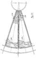
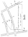
- the dartboard consists of a frame with spokes 1 and tires 2, which delimit a large number of fields 3 between them, in each of which a spring-loaded segment 4 is axially displaceably guided.
- the segment 4 has a target area 5 with a large number of holes 6 for receiving the dart, of which only a single hole is shown in FIGS. 2 and 3. 1 shows several, but not all, of the holes.
- Each hole 6 has a conical widening 7 on the side of the hit surface 5 to make it easier to pick up the dart.
- the dart segment 4 is guided axially displaceably within its field 3 lying between the spokes 1 and the tires 2.
- the direction of the axial displacement is indicated by the double arrow a.
- the dartboard consists of a carrier plate 8, a printed circuit board (contact plate) 9 thereon and a rubber mat 10 thereon.
- the contact plate 9 has contacts for displaying hits for each segment 4.
- Each segment 4 is at least one pin 11 for contacting the Contact plate 9 assigned to a hit.
- an adapter plate 12 is arranged which has clearances 13 which are penetrated by the pins 11 and in which the pins 11 are guided.
- the adapter plate 12 has lateral projections 14 with which it is supported on the spokes 1 or tires 2.
- the projections 14 are clamped between the rubber mat 10 and the rear ends of the spokes 1 or tires 2.
- the adapter plate 12 is arranged at a distance b from the rubber mat 10.
- On the back of the adapter plate 12 there is a wire bracket 15 running parallel to the latter, each of which penetrates an elongated hole 16 of each pin 11.
- hooks 17 are provided which receive the wire bracket 15.
- the pins 11 are connected in one piece to the segments 4 or are injection-molded onto them.
- the adapter plate 12 lies against the spoke 1 and against the rubber mat 10, as can be seen, for example, from FIG. 3.
- the spokes 1 and the tires 2 consist of steel strips.
- the pins 11 are molded onto the dart segment 4 as ribs. Your rear Ends are designed as contactors 18.
- the clearances 16 ensure the mobility of the dart segment. For this purpose, they have an extension in the axial direction a. An expansion perpendicular to this axial direction is also provided for play-free reception.
- the ribs forming the pins 11 and molded onto the dart segment 4 are arranged between the holes 6.
- the contactors 18 are in the rest position of the segment 4 on the rubber mat 10.
- the separate adapter plate 12 has clearances 13 through which the elongated ribs 11 of the dart segment 4 pass.
- the wire bracket 15 is pushed through the clearances 16 in the segment ribs 4 and holds the segment 4 back on the adapter plate 12 when a dart is pulled out.
- the wire bracket 15 is held in its locked position by guide channels 19.
- the hooks 17 also serve this purpose.
- the adapter plate 12 has lateral projections 14 at suitable points and is supported with them on the steel spokes 1.
- the clearances 16 in the elongated ribs 11 of the segment 4 are so large (in the a direction) that the wire bracket 15 does not restrict the freedom of movement of the segment 4 required for contacting.
- FIGS. 4 to 6 corresponds essentially to that of FIGS. 1 to 3.
- the pins are not formed by ribs which are integrally connected to the segment, but by pins 20 which are not integral with the segments which rest with their front side 21 on the rear side 22 of the segments 4.
- the contact is therefore achieved by separate axially displaceable pressure pins 20.
- the pins 20 are guided in the adapter plate 12 and lie against the dart segment 4 and the rubber mat 10.
- transverse steel axes 23, 24 are provided, which protrude beyond the side walls 25 of the segments 4 and which are mounted to be displaceable to a limited extent in elongated holes in the spokes 1.
- the steel axes 23, 24 are connected to the segments by an interference fit.
- stiffening projections 26 are provided at the bearing points of the steel axes 23, 24 in the side walls 25 of the segments.
- the steel axes 23, 24 protrude into the adjacent fields 3.
- the steel axes 23, 24 protrude the spokes 1 only by less than the tolerance of the segments 4 within the fields 3.
- the axis overhang over the spokes 1 can be 0.1 mm, for example, because the dart segment 4 has 0.2 mm tolerance to spokes 1 in each field 3 on each side.
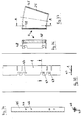
- the contact frame 27 which is connected to the steel axes 23, 24.
- the pins for contacting the contact plate 9 are located on the contact frame 27.
- the pins 11 are connected to the contact frame 27 in one piece.
- Snap connections are provided on the contact frame 27 for releasable locking with the steel axes 23, 24.
- the snap connections consist of segments 28, 29 which extend over an angular range of more than 180 °. The opening directions of the snap connections 28 and 29 are offset by 90 °.
- the snap connection 28 points outwards, while the snap connection 29 points forward.
- the contact frame 27 is first latched from behind with its snap connection 28 on the steel axis 23. Then the contact frame 27 around the steel axis 23 in the clockwise direction pivoted until the snap connection 29 snaps into the associated steel axis 24.
- the rubber mat 10 is located between the pins 11 and the contact plate 9.
- the contact frame 27 is elastic.
- the dart segment 4 rests on the steel spokes 1 with the steel axes 23, 24.
- the contact frame 27 is latched and releasably fastened to the steel axes 23 and 24 by the snap connections 28 and 29.
- FIGS. 9 and 10 show a variant of the embodiment according to FIGS. 7 and 8.
- the contact frame 27 is elastic; a rubber mat is therefore not necessary.
- the dart segment is then supported and reset next to the contact point.
- pot-shaped elevations 30 which rest against the contact plate and in the middle of which there is a contact elevation 31 which triggers the hit contact.
- the contact elevation 31 is thus located in front of the contact point 32 of the contact plate 9.
- the contact frame 27 also bears against the contact plate 9 when the segment 4 is in the non-operative position.
- the contact elevation 31 only triggers the hit contact when a dart hits.
- FIGS. 11 and 12 show a variant of the embodiment according to FIGS. 7 and 8. The only difference is that in FIGS. 11 and 12 the steel axes 23, 24 are shortened.
- the variant according to FIGS. 13 and 14 shows a modification of the embodiment according to FIGS. 9 and 10. Again, the only difference is that in the embodiment according to FIGS. 13 and 14 the steel axes 23 and 24 are opposite the variant of FIGS. 9 and 10 are shortened.
- FIGS. 15 to 17 Another embodiment is shown in FIGS. 15 to 17.
- steel axes 23, 24 extending in the transverse direction are provided in the segments 4, which protrude beyond the side walls 25 of the segments 4 and which are mounted to be displaceable to a limited extent in elongated holes in the spokes 1.
- the segments 4 In the vicinity of the steel axes 23, 24, the segments 4 have pins 33 pointing backwards, on each of which an elastic contact cap 34 which triggers the hit contact is arranged.
- Each contact cap 34 has a further projecting area 35, with which it is constantly supported next to the contact point 36 on the contact plate 9, and a less projecting area 37, which is spaced apart from the contact point 36 in the rest position and which triggers the contact when hit.
- the elastic cap (contact cap) 34 is attached to the pin 33.
- the contact cap 34 is supported next to the contact point 36 and presses the dart segment 4 away from the printed circuit board (contact plate). A rubber mat is therefore not required.
- the dart segment is constantly under tension.
- a thrown arrow, which strikes the dart segment moves the dart segment 4 to the printed circuit board (contact plate) 9.
- this elastic contact cap 34 Due to the lateral support of the contact cap 34 on its further projecting area 35, this elastic contact cap 34 is arched by the pin 33 and thus leads with its less projecting one Area 37 for contacting the contact point 36 on the contact plate 9.
- the contacting described by means of an elastic contact cap 34 can be combined with all the options for retaining the dart segments 4.
- FIGS. 15 to 17 the variant of FIGS. 18 to 20 has shortened steel axes 23, 24.
- steel axes 23, 24 are provided, which run in the segments 4 in the transverse direction.
- the steel axes 23 can be bent.
- the steel axes 23, 24 carry resilient elements 38, which consist of a first, resilient sub-element 39, which rests under prestress against the contact plate 9 next to the contact point 36 (FIG. 23), and a second sub-element 40, which is in the rest position is spaced from the contact point 36 and which triggers the contact upon a hit.
- the second sub-element 40 is also elastic.
- the resilient elements 38 are rotationally symmetrical. They consist of rubber-like elastic bodies made of flexible plastic.
- the resilient elements 38 consist of two thickened areas 39, 40, namely the first partial element 39 and the second partial element 40, between which there is an area 41 with a smaller diameter.
- the resilient element 38 rests under prestress on the contact plate 9, namely at a distance from the contact point 36.
- the second element 40 touches the contact plate 9 at the contact point 36.
- the steel axis 23 rests on a trough-shaped depression 43 in the side wall 25 of the dart segment 4. At this bearing point, the steel axis 23 therefore has a certain possibility of displacement.
- the steel axis is supported on the edge 44 of the spoke 1. The segment 4 is retained in this way.
- the elastic roller 38 is supported with its large diameter 39 next to the contact point 36 on the circuit board 9; it resiliently rests the dart segment 4 and keeps it under pressure.
- a thrown arrow 42 moves the dart segment 4 in the direction of the printed circuit board 9, as a result of which the large diameter 39 of the elastic roller 38 is compressed and the small diameter 40 touches the contact point 36 and leads to contact. From the illustration in Fig. 22 it can be seen that only the steel axis 23 abuts the spoke 1, but not the segment 4 or its side wall 25.
- FIGS. 31 to 37 Another embodiment is shown in FIGS. 31 to 37.
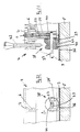
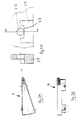
- a movable, U-shaped slider 45 engages or engages behind the spoke 1.
- a pin 46 is pressed into the slider 45.
- the pin 46 engages on both sides of both guide grooves 47 of the spokes 1 and guide grooves 48 of the side walls 25 of the segments 4.
- the guide grooves 47 of the spokes 1 on the one hand and the guide grooves 48 of the segments 4 on the other hand run in an L-shaped manner, so that the pins 46 of the slider 45 inserted into the guide grooves 47 of the spokes 1 and can be locked with the guide grooves 48 of the segments 4.
- the latched position is shown in FIG. 30.
- the dart segments 4 are locked.
- FIG. 31 shows the position in which the U-shaped slides 45 are inserted with their pins 46 into the guide grooves 47 of the spokes 1.
- the dart segments can then be brought down into position past the pins 46.
- the slide 45 is pushed to the left, so that the locked position shown in FIG. 30 is reached.
- the guide grooves 47 of the spokes 1 are open at the bottom in order to be able to insert the slide (FIG. 31).
- the slide 45 is pushed all the way to the right (FIG. 31) in order to be able to push the segments 4 into the associated fields from above or from the front.
- the slide 25 is moved to the left so that the segments 4 are locked by the pins 46.
- segment 4 are guided axially displaceably between the tires 2.
- the contact plate 9 is located on the rear side of the segments 4 and the tires 2 facing away from the darts 42; again the carrier plate 8 is arranged behind it.
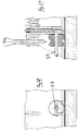
- the segments 4 have rearward-facing pins 33 (in the segment 4 shown on the left in FIG. 38, this pin 33 is omitted for the sake of the simplified drawing).
- An elastic contact cap 34 ' which triggers the hit contact is arranged on the pin 33.
- the contact cap has three elevations 51 arranged in a triangle, with which it already bears against the contact plate 9 in the idle state with prestress.
- the contact to be triggered by the contact cap lies within the triangle formed by the elevations 51. 38 to 40, only two elevations 51 can be seen in each case, since the third lies in front of the drawing plane.
- the elevations 51 are spherical, more precisely part-spherical.
- the contact cap On its side facing the darts 42, the contact cap has a forward-facing groove 52, which is realized by a material recess.
- the groove 52 is approximately semicircular in cross section. It lies next to the pin 33 and increases the elasticity of the contact cap 34 '.
- segment 4 shown on the right is in the rest position. It is slightly biased by the contact cap 34 '.
- the segment 4 shown on the left in FIG. 39 is moved backwards by the arrow 42 (in the drawing below), that is to say to the contact plate 9.
- the contact cap 34 ' is deformed toward the contact plate 9, as indicated by the reference number 53.
- the contact cap 34 ' creates contacting through this deformation.
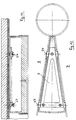
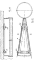
- the tires 2 each have a wedge-shaped outlet 54 on their front sides facing the darts 42, the wedge tip pointing forward, ie toward the darts 42.
- the wedge-shaped outlet 54 is rounded towards the front, as indicated by reference number 55.
- the wedge-shaped outlet 54 has an overlap towards segment 4.
- the distance D between the opposite outer corners of the wedge-shaped profile is therefore greater than the thickness d in the remaining area of the tires 2 (and also the spokes not shown in the drawings in FIGS. 38 to 40).
- the wedge-shaped overlaps 54 are so large that jamming of the dart 42 between the tires 2 (or the spokes) and the associated segment 4 is excluded. A movement of the segments 4 forward is prevented by the projections 14.
- the wedge-shaped outlets 44 are rounded inward toward the rear, as indicated by reference number 57.
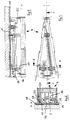
- the spokes 1 and the tires 2 have inward elevations 58 on their rear sides facing away from the darts 42, which are spherical or partially spherical. These spherical elevations (thickenings) 58 at the rear (lower in the drawing) end of the spokes or tires prevent the segments from falling out when the contact plate 9 is folded away. As can be seen in FIG. 40 on the basis of the segment 4 shown there on the left, the segments 4 cannot fall out to the rear (in the drawing of FIG. 40 below) even when the contact plate 9 is folded away. It is nevertheless possible to remove the segments: by pushing on the segments 4 from the dart side, the ribs (spokes 1 and tires 2) move sideways, and the segments 4 can be replaced.
Landscapes
- General Engineering & Computer Science (AREA)
- Engineering & Computer Science (AREA)
- Toys (AREA)
- Aiming, Guidance, Guns With A Light Source, Armor, Camouflage, And Targets (AREA)
- Inorganic Insulating Materials (AREA)
- Medicinal Preparation (AREA)
- Switches Operated By Changes In Physical Conditions (AREA)
- Acyclic And Carbocyclic Compounds In Medicinal Compositions (AREA)
- Crystals, And After-Treatments Of Crystals (AREA)
- Refuge Islands, Traffic Blockers, Or Guard Fence (AREA)
- Tires In General (AREA)
- Portable Nailing Machines And Staplers (AREA)
- Automatic Assembly (AREA)
- Braking Arrangements (AREA)
Applications Claiming Priority (3)
| Application Number | Priority Date | Filing Date | Title |
|---|---|---|---|
| DE4004409 | 1990-02-13 | ||
| DE4004409A DE4004409C2 (de) | 1990-02-13 | 1990-02-13 | Wurfpfeil-Scheibe |
| EP91101804A EP0442395B1 (fr) | 1990-02-13 | 1991-02-08 | Cible pour jeu de fléchettes |
Related Parent Applications (2)
| Application Number | Title | Priority Date | Filing Date |
|---|---|---|---|
| EP91101804A Division EP0442395B1 (fr) | 1990-02-13 | 1991-02-08 | Cible pour jeu de fléchettes |
| EP91101804.2 Division | 1991-02-08 |
Publications (3)
| Publication Number | Publication Date |
|---|---|
| EP0645598A2 true EP0645598A2 (fr) | 1995-03-29 |
| EP0645598A3 EP0645598A3 (fr) | 1995-08-02 |
| EP0645598B1 EP0645598B1 (fr) | 1998-04-29 |
Family
ID=6400051
Family Applications (6)
| Application Number | Title | Priority Date | Filing Date |
|---|---|---|---|
| EP91101804A Expired - Lifetime EP0442395B1 (fr) | 1990-02-13 | 1991-02-08 | Cible pour jeu de fléchettes |
| EP94119527A Expired - Lifetime EP0653602B1 (fr) | 1990-02-13 | 1991-02-08 | Cible pour jeu de fléchettes |
| EP94119547A Expired - Lifetime EP0645598B1 (fr) | 1990-02-13 | 1991-02-08 | Cible pour jeu de fléchettes |
| EP94119526A Expired - Lifetime EP0648995B1 (fr) | 1990-02-13 | 1991-02-08 | Cible pour jeu de fléchettes |
| EP94119546A Expired - Lifetime EP0648996B1 (fr) | 1990-02-13 | 1991-02-08 | Cible pour jeu de fléchettes |
| EP97103625A Ceased EP0781974A3 (fr) | 1990-02-13 | 1991-02-08 | Cible pour jeu de fléchettes |
Family Applications Before (2)
| Application Number | Title | Priority Date | Filing Date |
|---|---|---|---|
| EP91101804A Expired - Lifetime EP0442395B1 (fr) | 1990-02-13 | 1991-02-08 | Cible pour jeu de fléchettes |
| EP94119527A Expired - Lifetime EP0653602B1 (fr) | 1990-02-13 | 1991-02-08 | Cible pour jeu de fléchettes |
Family Applications After (3)
| Application Number | Title | Priority Date | Filing Date |
|---|---|---|---|
| EP94119526A Expired - Lifetime EP0648995B1 (fr) | 1990-02-13 | 1991-02-08 | Cible pour jeu de fléchettes |
| EP94119546A Expired - Lifetime EP0648996B1 (fr) | 1990-02-13 | 1991-02-08 | Cible pour jeu de fléchettes |
| EP97103625A Ceased EP0781974A3 (fr) | 1990-02-13 | 1991-02-08 | Cible pour jeu de fléchettes |
Country Status (4)
| Country | Link |
|---|---|
| EP (6) | EP0442395B1 (fr) |
| AT (5) | ATE165654T1 (fr) |
| DE (7) | DE4042477C2 (fr) |
| ES (4) | ES2093036T3 (fr) |
Cited By (1)
| Publication number | Priority date | Publication date | Assignee | Title |
|---|---|---|---|---|
| EP0882942A3 (fr) * | 1997-06-05 | 2000-05-24 | Valley Recreation Products Inc. | Cible |
Families Citing this family (6)
| Publication number | Priority date | Publication date | Assignee | Title |
|---|---|---|---|---|
| DE4214364C2 (de) * | 1992-04-30 | 1998-07-16 | Nsm Ag | Wurfpfeil-Scheibe |
| US5626344A (en) * | 1995-07-10 | 1997-05-06 | Huang; Chun-Mu | Double bull's-eye device |
| ES2146496B1 (es) * | 1996-02-05 | 2001-02-16 | Quetglas Arino Miguel Angel | Perfeccionamientos en la construccion de armazones de celosia, para el alojamiento y retencion, desplazable, de los segmentos en dianas para el juego de dardos. |
| ES2140270B1 (es) * | 1996-10-16 | 2000-09-01 | Inter Therm S L | Sistema de construccion de una diana para aparatos recreativos electromecanicos. |
| TW333329U (en) * | 1997-08-01 | 1998-06-01 | kun-lin Zhuo | Improved structure of a dart board |
| TW362766U (en) * | 1998-09-09 | 1999-06-21 | kun-lin Zhuo | Improvement for constitution of target block of dart target |
Family Cites Families (8)
| Publication number | Priority date | Publication date | Assignee | Title |
|---|---|---|---|---|
| US4057251A (en) * | 1976-05-10 | 1977-11-08 | Arachnid, Incorporated | Dart game with apertured target plates resiliently mounted |
| US4516781A (en) * | 1982-11-17 | 1985-05-14 | Industrial Design Electronic Associates, Inc. | Dart game with two microcomputers |
| US4561660A (en) * | 1983-11-14 | 1985-12-31 | Arachnid, Inc. | Dart machine with electronic matrix |
| US4586716A (en) * | 1984-04-17 | 1986-05-06 | Industrial Design Electronic Associates, Inc. | Double bullseye for dart game |
| US4635940A (en) * | 1985-06-26 | 1987-01-13 | William E. McClure | Dart board assembly for an electronic dart game |
| AU7790287A (en) * | 1987-09-21 | 1989-03-09 | Lin, J. | Circuitry for electronic scoring dartboard |
| US4836556A (en) * | 1987-12-11 | 1989-06-06 | Kidde Recreational Products Inc. | Dart game target construction |
| DE3834625A1 (de) * | 1988-08-08 | 1990-02-15 | Nsm Apparatebau Gmbh Kg | Wurfpfeil-scheibe |
-
1990
- 1990-02-13 DE DE4042477A patent/DE4042477C2/de not_active Expired - Fee Related
- 1990-02-13 DE DE4004409A patent/DE4004409C2/de not_active Expired - Fee Related
-
1991
- 1991-02-08 ES ES91101804T patent/ES2093036T3/es not_active Expired - Lifetime
- 1991-02-08 AT AT94119547T patent/ATE165654T1/de not_active IP Right Cessation
- 1991-02-08 EP EP91101804A patent/EP0442395B1/fr not_active Expired - Lifetime
- 1991-02-08 AT AT91101804T patent/ATE145279T1/de active
- 1991-02-08 EP EP94119527A patent/EP0653602B1/fr not_active Expired - Lifetime
- 1991-02-08 EP EP94119547A patent/EP0645598B1/fr not_active Expired - Lifetime
- 1991-02-08 EP EP94119526A patent/EP0648995B1/fr not_active Expired - Lifetime
- 1991-02-08 EP EP94119546A patent/EP0648996B1/fr not_active Expired - Lifetime
- 1991-02-08 AT AT94119527T patent/ATE180051T1/de not_active IP Right Cessation
- 1991-02-08 ES ES94119526T patent/ES2115142T3/es not_active Expired - Lifetime
- 1991-02-08 AT AT94119526T patent/ATE165655T1/de not_active IP Right Cessation
- 1991-02-08 DE DE59108975T patent/DE59108975D1/de not_active Expired - Fee Related
- 1991-02-08 DE DE59108974T patent/DE59108974D1/de not_active Expired - Fee Related
- 1991-02-08 ES ES94119546T patent/ES2115143T3/es not_active Expired - Lifetime
- 1991-02-08 EP EP97103625A patent/EP0781974A3/fr not_active Ceased
- 1991-02-08 DE DE59108335T patent/DE59108335D1/de not_active Expired - Fee Related
- 1991-02-08 DE DE59108976T patent/DE59108976D1/de not_active Expired - Fee Related
- 1991-02-08 AT AT94119546T patent/ATE165656T1/de not_active IP Right Cessation
- 1991-02-08 ES ES94119547T patent/ES2115144T3/es not_active Expired - Lifetime
- 1991-02-08 DE DE59109128T patent/DE59109128D1/de not_active Expired - Fee Related
Cited By (1)
| Publication number | Priority date | Publication date | Assignee | Title |
|---|---|---|---|---|
| EP0882942A3 (fr) * | 1997-06-05 | 2000-05-24 | Valley Recreation Products Inc. | Cible |
Also Published As
| Publication number | Publication date |
|---|---|
| EP0781974A3 (fr) | 1997-07-09 |
| EP0653602B1 (fr) | 1999-05-12 |
| EP0442395A3 (en) | 1992-07-08 |
| ATE165655T1 (de) | 1998-05-15 |
| EP0648995B1 (fr) | 1998-04-29 |
| DE4004409C2 (de) | 1994-01-27 |
| ES2093036T3 (es) | 1996-12-16 |
| ES2115142T3 (es) | 1998-06-16 |
| ATE180051T1 (de) | 1999-05-15 |
| DE59109128D1 (de) | 1999-06-17 |
| EP0442395A2 (fr) | 1991-08-21 |
| ATE165654T1 (de) | 1998-05-15 |
| EP0648995A3 (fr) | 1995-08-02 |
| ES2115143T3 (es) | 1998-06-16 |
| EP0645598A3 (fr) | 1995-08-02 |
| EP0648996B1 (fr) | 1998-04-29 |
| DE4004409A1 (de) | 1991-08-14 |
| EP0442395B1 (fr) | 1996-11-13 |
| EP0648995A2 (fr) | 1995-04-19 |
| DE59108975D1 (de) | 1998-06-04 |
| DE59108976D1 (de) | 1998-06-04 |
| EP0648996A3 (fr) | 1995-08-02 |
| EP0648996A2 (fr) | 1995-04-19 |
| ATE145279T1 (de) | 1996-11-15 |
| EP0781974A2 (fr) | 1997-07-02 |
| EP0653602A2 (fr) | 1995-05-17 |
| EP0645598B1 (fr) | 1998-04-29 |
| DE59108335D1 (de) | 1996-12-19 |
| DE4042477C2 (de) | 1996-01-25 |
| ATE165656T1 (de) | 1998-05-15 |
| EP0653602A3 (fr) | 1995-08-02 |
| ES2115144T3 (es) | 1998-06-16 |
| DE59108974D1 (de) | 1998-06-04 |
Similar Documents
| Publication | Publication Date | Title |
|---|---|---|
| DE68907452T2 (de) | Verbindungsglied in einem Scheibenwischer. | |
| DE202008007783U1 (de) | In einem Loch befestigbares Halteelement | |
| EP0231440A2 (fr) | Pare-soleil pour véhicules | |
| DE69415254T3 (de) | Verbindungselement für Scheibenwischerblatt | |
| DE3833229A1 (de) | Magazin fuer eine feuerwaffe | |
| DE3834625C2 (fr) | ||
| DE4037706C1 (fr) | ||
| EP0442395A2 (fr) | Cible pour jeu de fléchettes | |
| AT2996U1 (de) | Achssicherung für die schwenkachse eines handstempels sowie handstempel | |
| DE3618973A1 (de) | Hoeheneinstellbare vorrichtung an einem sicherheitsgurt fuer kraftfahrzeuge | |
| DE2541922B2 (de) | Verriegelbarer Drucktastenschalter | |
| DE19820336A1 (de) | Armlehne für einen Kraftfahrzeugsitz | |
| DE19721757C1 (de) | Vorrichtung zur Befestigung von Anbauteilen | |
| DE4304173C2 (de) | Gurtschnalle | |
| DE2814335A1 (de) | Kopplungsschloss fuer einen sicherheitsgurt | |
| DE29720862U1 (de) | Sicherheitsschalter | |
| DE4035856C2 (fr) | ||
| DE2208289C2 (de) | Belüftungsvorrichtung | |
| CH712082A2 (de) | Linearführungseinrichtung. | |
| DE102021107013A1 (de) | Bauteilanordnung für Kraftfahrzeuge und Verfahren zum Verbinden von Bauteilen eines Kraftfahrzeugs, sowie Instrumententafel und Fahrzeugtür | |
| EP0837252B1 (fr) | Elément de fixation | |
| EP2366590B1 (fr) | Clip de fixation | |
| DE3606336A1 (de) | Schreibgeraet mit einem gehaeuse | |
| EP0123260A2 (fr) | Enjoliveur de roue | |
| DE7538415U (de) | Schaltelement |
Legal Events
| Date | Code | Title | Description |
|---|---|---|---|
| PUAI | Public reference made under article 153(3) epc to a published international application that has entered the european phase |
Free format text: ORIGINAL CODE: 0009012 |
|
| 17P | Request for examination filed |
Effective date: 19941221 |
|
| AC | Divisional application: reference to earlier application |
Ref document number: 442395 Country of ref document: EP |
|
| AK | Designated contracting states |
Kind code of ref document: A2 Designated state(s): AT BE CH DE DK ES FR GB GR IT LI LU NL SE |
|
| PUAL | Search report despatched |
Free format text: ORIGINAL CODE: 0009013 |
|
| AK | Designated contracting states |
Kind code of ref document: A3 Designated state(s): AT BE CH DE DK ES FR GB GR IT LI LU NL |
|
| RBV | Designated contracting states (corrected) |
Designated state(s): AT BE CH DE DK ES FR GB GR IT LI LU NL SE |
|
| 17Q | First examination report despatched |
Effective date: 19961031 |
|
| GRAG | Despatch of communication of intention to grant |
Free format text: ORIGINAL CODE: EPIDOS AGRA |
|
| GRAG | Despatch of communication of intention to grant |
Free format text: ORIGINAL CODE: EPIDOS AGRA |
|
| GRAH | Despatch of communication of intention to grant a patent |
Free format text: ORIGINAL CODE: EPIDOS IGRA |
|
| GRAH | Despatch of communication of intention to grant a patent |
Free format text: ORIGINAL CODE: EPIDOS IGRA |
|
| GRAA | (expected) grant |
Free format text: ORIGINAL CODE: 0009210 |
|
| AC | Divisional application: reference to earlier application |
Ref document number: 442395 Country of ref document: EP |
|
| AK | Designated contracting states |
Kind code of ref document: B1 Designated state(s): AT BE CH DE DK ES FR GB GR IT LI LU NL SE |
|
| PG25 | Lapsed in a contracting state [announced via postgrant information from national office to epo] |
Ref country code: GR Free format text: LAPSE BECAUSE OF NON-PAYMENT OF DUE FEES Effective date: 19980429 Ref country code: GB Free format text: LAPSE BECAUSE OF FAILURE TO SUBMIT A TRANSLATION OF THE DESCRIPTION OR TO PAY THE FEE WITHIN THE PRESCRIBED TIME-LIMIT Effective date: 19980429 |
|
| REF | Corresponds to: |
Ref document number: 165654 Country of ref document: AT Date of ref document: 19980515 Kind code of ref document: T |
|
| REG | Reference to a national code |
Ref country code: CH Ref legal event code: EP |
|
| REF | Corresponds to: |
Ref document number: 59108974 Country of ref document: DE Date of ref document: 19980604 |
|
| REG | Reference to a national code |
Ref country code: ES Ref legal event code: FG2A Ref document number: 2115144 Country of ref document: ES Kind code of ref document: T3 |
|
| ET | Fr: translation filed | ||
| ITF | It: translation for a ep patent filed | ||
| PG25 | Lapsed in a contracting state [announced via postgrant information from national office to epo] |
Ref country code: SE Free format text: LAPSE BECAUSE OF FAILURE TO SUBMIT A TRANSLATION OF THE DESCRIPTION OR TO PAY THE FEE WITHIN THE PRESCRIBED TIME-LIMIT Effective date: 19980729 Ref country code: DK Free format text: LAPSE BECAUSE OF FAILURE TO SUBMIT A TRANSLATION OF THE DESCRIPTION OR TO PAY THE FEE WITHIN THE PRESCRIBED TIME-LIMIT Effective date: 19980729 |
|
| GBV | Gb: ep patent (uk) treated as always having been void in accordance with gb section 77(7)/1977 [no translation filed] |
Effective date: 19980429 |
|
| PG25 | Lapsed in a contracting state [announced via postgrant information from national office to epo] |
Ref country code: LU Free format text: LAPSE BECAUSE OF NON-PAYMENT OF DUE FEES Effective date: 19990208 |
|
| PGFP | Annual fee paid to national office [announced via postgrant information from national office to epo] |
Ref country code: ES Payment date: 19990211 Year of fee payment: 9 |
|
| PGFP | Annual fee paid to national office [announced via postgrant information from national office to epo] |
Ref country code: FR Payment date: 19990215 Year of fee payment: 9 |
|
| PGFP | Annual fee paid to national office [announced via postgrant information from national office to epo] |
Ref country code: BE Payment date: 19990219 Year of fee payment: 9 Ref country code: AT Payment date: 19990219 Year of fee payment: 9 |
|
| PGFP | Annual fee paid to national office [announced via postgrant information from national office to epo] |
Ref country code: NL Payment date: 19990228 Year of fee payment: 9 |
|
| PGFP | Annual fee paid to national office [announced via postgrant information from national office to epo] |
Ref country code: CH Payment date: 19990304 Year of fee payment: 9 |
|
| PLBE | No opposition filed within time limit |
Free format text: ORIGINAL CODE: 0009261 |
|
| STAA | Information on the status of an ep patent application or granted ep patent |
Free format text: STATUS: NO OPPOSITION FILED WITHIN TIME LIMIT |
|
| 26N | No opposition filed | ||
| PG25 | Lapsed in a contracting state [announced via postgrant information from national office to epo] |
Ref country code: DE Free format text: LAPSE BECAUSE OF NON-PAYMENT OF DUE FEES Effective date: 19991201 |
|
| PG25 | Lapsed in a contracting state [announced via postgrant information from national office to epo] |
Ref country code: AT Free format text: LAPSE BECAUSE OF NON-PAYMENT OF DUE FEES Effective date: 20000208 |
|
| PG25 | Lapsed in a contracting state [announced via postgrant information from national office to epo] |
Ref country code: ES Free format text: LAPSE BECAUSE OF EXPIRATION OF PROTECTION Effective date: 20000209 |
|
| PG25 | Lapsed in a contracting state [announced via postgrant information from national office to epo] |
Ref country code: BE Free format text: LAPSE BECAUSE OF NON-PAYMENT OF DUE FEES Effective date: 20000228 |
|
| PG25 | Lapsed in a contracting state [announced via postgrant information from national office to epo] |
Ref country code: LI Free format text: LAPSE BECAUSE OF NON-PAYMENT OF DUE FEES Effective date: 20000229 Ref country code: CH Free format text: LAPSE BECAUSE OF NON-PAYMENT OF DUE FEES Effective date: 20000229 |
|
| BERE | Be: lapsed |
Owner name: NSM A.G. Effective date: 20000228 |
|
| PG25 | Lapsed in a contracting state [announced via postgrant information from national office to epo] |
Ref country code: NL Free format text: LAPSE BECAUSE OF NON-PAYMENT OF DUE FEES Effective date: 20000901 |
|
| REG | Reference to a national code |
Ref country code: CH Ref legal event code: PL |
|
| PG25 | Lapsed in a contracting state [announced via postgrant information from national office to epo] |
Ref country code: FR Free format text: LAPSE BECAUSE OF NON-PAYMENT OF DUE FEES Effective date: 20001031 |
|
| NLV4 | Nl: lapsed or anulled due to non-payment of the annual fee |
Effective date: 20000901 |
|
| REG | Reference to a national code |
Ref country code: FR Ref legal event code: ST |
|
| REG | Reference to a national code |
Ref country code: ES Ref legal event code: FD2A Effective date: 20011010 |
|
| PG25 | Lapsed in a contracting state [announced via postgrant information from national office to epo] |
Ref country code: IT Free format text: LAPSE BECAUSE OF NON-PAYMENT OF DUE FEES Effective date: 20050208 |