EP0645837A2 - Empfänger und Antenne vereinigt im Empfänger - Google Patents
Empfänger und Antenne vereinigt im Empfänger Download PDFInfo
- Publication number
- EP0645837A2 EP0645837A2 EP94307063A EP94307063A EP0645837A2 EP 0645837 A2 EP0645837 A2 EP 0645837A2 EP 94307063 A EP94307063 A EP 94307063A EP 94307063 A EP94307063 A EP 94307063A EP 0645837 A2 EP0645837 A2 EP 0645837A2
- Authority
- EP
- European Patent Office
- Prior art keywords
- receiver
- antenna
- circuit board
- bobbin
- printed circuit
- Prior art date
- Legal status (The legal status is an assumption and is not a legal conclusion. Google has not performed a legal analysis and makes no representation as to the accuracy of the status listed.)
- Withdrawn
Links
- 230000005684 electric field Effects 0.000 claims abstract description 26
- 229920003002 synthetic resin Polymers 0.000 claims abstract description 8
- 239000000057 synthetic resin Substances 0.000 claims abstract description 8
- 239000000463 material Substances 0.000 claims description 5
- 230000005404 monopole Effects 0.000 claims description 3
- 230000006866 deterioration Effects 0.000 description 5
- 230000008901 benefit Effects 0.000 description 4
- 238000010586 diagram Methods 0.000 description 4
- 230000005855 radiation Effects 0.000 description 4
- 230000000694 effects Effects 0.000 description 3
- 238000004519 manufacturing process Methods 0.000 description 3
- 239000004677 Nylon Substances 0.000 description 2
- 238000010276 construction Methods 0.000 description 2
- 229920001778 nylon Polymers 0.000 description 2
- 239000007787 solid Substances 0.000 description 2
- 229930182556 Polyacetal Natural products 0.000 description 1
- 239000004743 Polypropylene Substances 0.000 description 1
- 244000090125 Solidago odora Species 0.000 description 1
- 239000003990 capacitor Substances 0.000 description 1
- 230000008859 change Effects 0.000 description 1
- 230000005672 electromagnetic field Effects 0.000 description 1
- 229920006324 polyoxymethylene Polymers 0.000 description 1
- -1 polypropylene Polymers 0.000 description 1
- 229920001155 polypropylene Polymers 0.000 description 1
- 229920005989 resin Polymers 0.000 description 1
- 239000011347 resin Substances 0.000 description 1
- 230000004044 response Effects 0.000 description 1
- 230000002195 synergetic effect Effects 0.000 description 1
- 238000004804 winding Methods 0.000 description 1
Images



Classifications
-
- H—ELECTRICITY
- H01—ELECTRIC ELEMENTS
- H01Q—ANTENNAS, i.e. RADIO AERIALS
- H01Q21/00—Antenna arrays or systems
- H01Q21/24—Combinations of antenna units polarised in different directions for transmitting or receiving circularly and elliptically polarised waves or waves linearly polarised in any direction
-
- H—ELECTRICITY
- H01—ELECTRIC ELEMENTS
- H01Q—ANTENNAS, i.e. RADIO AERIALS
- H01Q1/00—Details of, or arrangements associated with, antennas
- H01Q1/12—Supports; Mounting means
- H01Q1/1271—Supports; Mounting means for mounting on windscreens
-
- H—ELECTRICITY
- H01—ELECTRIC ELEMENTS
- H01Q—ANTENNAS, i.e. RADIO AERIALS
- H01Q1/00—Details of, or arrangements associated with, antennas
- H01Q1/27—Adaptation for use in or on movable bodies
- H01Q1/32—Adaptation for use in or on road or rail vehicles
- H01Q1/3208—Adaptation for use in or on road or rail vehicles characterised by the application wherein the antenna is used
- H01Q1/3233—Adaptation for use in or on road or rail vehicles characterised by the application wherein the antenna is used particular used as part of a sensor or in a security system, e.g. for automotive radar, navigation systems
-
- H—ELECTRICITY
- H01—ELECTRIC ELEMENTS
- H01Q—ANTENNAS, i.e. RADIO AERIALS
- H01Q1/00—Details of, or arrangements associated with, antennas
- H01Q1/36—Structural form of radiating elements, e.g. cone, spiral, umbrella; Particular materials used therewith
- H01Q1/362—Structural form of radiating elements, e.g. cone, spiral, umbrella; Particular materials used therewith for broadside radiating helical antennas
Definitions
- the present invention relates generally to a receiver and an antenna, and more particularly, to an antenna incorporated in a receiver, the combination of which is used as part of a "wireless control system" for the remote control of a vehicle mounted equipment by low intensity radio waves.
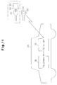
- Fig. 11 In the recent past, various types of motor vehicle equipment have been capable of remote control operation due to various types of wireless or remote control systems, one such system, is illustrated in Fig. 11, and includes a transmitter 33 that outputs a low intensity radio wave to a receiver 35 mounted on a vehicle 34.
- the transmitter 33 is typically incorporated into an ignition key 31 or a key holder 32 for convenience and ease in use by the vehicle's operator.
- the receiver 35 In response to the low intensity signal, the receiver 35 effects operation of the equipment 36. It is possible in this way to lock or unlock the vehicle's doors, start the vehicle's engine as well as to control other vehicle functions at a location remote from the vehicle 34.
- the receiver's antenna for such a system was positioned outside the vehicle 34.
- the receiver and antenna are mounted under the seat and in the trunk.
- the low intensity radio wave generally uses a frequency in the ultra high frequency (UHF) band.
- UHF ultra high frequency
- a compact high-efficiency helical antenna is normally used.
- the tuning frequency of the antenna may fluctuate due to changes in the electric field state caused by changes in seat position.
- securing means are adapted.
- Such securing means provide yet another limitation on the relatively unavailable space needed for the antenna and receiver.
- a receiver positioned in a vehicle has a plurality of antennas arranged in accordance with the electric field intensity surrounding the antennas and varies depending on the position of the receiver in the vehicle.
- Figs. 1 to 6 illustrates a first embodiment of an antenna built into the receiver according to the present invention.
- a remote control system has a transmitter 15 incorporated in an ignition key (not shown) for transmitting low intensity electric signals.
- a receiver 17 positioned in an automobile 16 receives the signals from the transmitter 15.
- the equipment 18 mounted in the automobile 16 operates according to the signals to selectively open and close the car door.
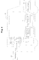
- Figs. 1 to 3 are perspective views illustrating three modes or patterns in which an antenna is incorporated into a receiver built on a printed circuit board according to the first embodiment of the present invention.
- Fig. 1 shows the receiver and antenna of the first mode.
- Two helical antennas 12a and 12b having the same constitution are set on a printed circuit board 11 to be built in the receiver 17.
- the central axes 13a and 13b of the antennas 12a and 12b are parallel to each other and correspond to z axis as shown in Fig. 1.
- Fig. 2 shows the receiver and antenna of the second mode.
- Two helical antennas 12x and 12y having the same constitution are set on a printed circuit board 11.
- the central axes 13x and 13y of the antennas 12x and 12y are perpendicular to each other and correspond to x and y axes shown in Fig. 2.
- Fig. 3 shows the receiver and antenna of the third mode.
- Three helical antennas 12x to 12z having the same constitution are set on a printed circuit board 11.
- the central axes of 13x to 13z of the associated antennas 12x to 12z are perpendicular to each other and correspond to x, y, and z axes in Fig. 3.
- a synthetic matching circuit 13 and a receiving circuit 14 are formed on a printed circuit board 11.
- Signal combination and impedance matching between the antennas 12a and 12b or 12x to 12z and the receiving circuit 14 is performed by the synthetic matching circuit 13. That is, the signals from each of the antennas 12a and 12b or 12x to 12z are synthesized by the receiving circuit 14.
- a further function of the synthetic matching circuit 13 is as a general impedance matching circuit comprising a coil and a capacitor.
- the first advantage is that the antenna volume increases and thereby the frequency band width of the antenna can be increased because each mode synthesizes operations by using the antennas 12a and 12b or 12x to 12z. As a result, it is possible to decrease the effects of a changing electric field, due to differences in the positioning or setting of the receiver, on reception characteristics of the receiver 17. This, in turn, increases the distances over which the remote control system functions, as well as improve the directivity of the system.
- the second advantage is that optimum signal reception characteristics can be obtained by properly selecting one first through third modes or antenna receiver 17 configurations appropriate to the state of the electric-field (intensity or vector magnitude of the electric field) an any given instance.
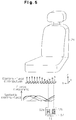
- the first mode shown in Fig. 1 is effective for setting the receiver 17 under the seat 21. This is because, referring to vector notation, even if the z-axis component of the electric field corresponding to one of the two or more vertically parallel antennas, e.g. 12a, is small, it is possible to match the z-axis component of the electric field corresponding to the other antenna 12b to a certain degree. Therefore, an adequate receiving gain can be obtained when both of the antennas 12a and 12b are used.
- the electric-field vector may differ significantly depending on the receiver 17 setting or position in the automobile 16.
- the antenna 12y (y axis) has the directivity, relative to the automobile 16, as shown in Fig. 6(a) and the antenna 12x (x axis) has the directivity shown in Fig. 6(b).
- the second mode shown in Fig. 2 would be most effective. That is, in the second mode electric fields in two directions of x and y axes can be received.
- This arrangement of antennas 12x and 12y results in a radiation distribution pattern as shown in Fig. 6(c), assuring adequate reception of gain.
- the third mode shown in Fig. 3 can receive electric fields in three directions of x, y, and z axes because it is provided with the antenna 12z corresponding to z axis in addition to the case of the second mode.
- This mode can be utilized where in a more complicated electric-field vector states exist.
- the directional property of the receiver can be made almost nondirectional.
- the effective distance of operating a "remote control system" and the directivity of the system remain uninfluenced by differences in the receiver 17 setting position in the automobile 16.
- Fig. 7 shows a plan view of the antenna to be incorporated in the receiver 17 of the first mode of this embodiment and Fig. 8 shows a side view of the antenna.
- An antenna 101 of the first mode comprises a cylindrical bobbin 102 and a dipole helical antenna 103 wound on the bobbin 102.
- the bobbin 102 is made of a material with a proper permittivity and has a flanged antenna-securing member 104 at its both ends, and the securing member 104 has a notch 104a.
- the notch 104a is fitted to the end of a printed circuit board 105 having an internal circuit of a receiver 17. With this structure, it is possible to secure the antenna 101 to the printed circuit board 105.
- the end 103a of the antenna 103 is inserted into a through-hole 105a formed on the printed circuit board 105. Then, the end 103a is soldered to a printed pattern 105b formed on the back of the printed circuit board 105.
- the internal circuit of the receiver can be connected to the antenna 101.
- FIG. 9 shows a plan view of an antenna to be incorporated in the receiver 17 of the second mode of this embodiment and Fig. 10 shows a side view of the antenna.
- An antenna 111 of this mode comprises a cylindrical bobbin 112 having the bottom and a monopole helical antenna 113 wound on the bobbin 112.
- the bobbin 112 is made of a material having a proper permittivity and has a threaded hole (not shown) at its bottom.
- the bobbin 112 is set on a printed circuit board 115 serving as a component of the receiver 17.
- a bolt 116 is inserted into a threaded hole (not shown) formed on the board 115 and the threaded hole at the bottom of the bobbin 112 and secured with a nut 117.
- the bobbin 112 has a protrusion 112a at its outer wall so as to secure a lead section 113b following the end 113a of the antenna 113 with the protrusion 112a.
- the bobbins 102 and 112 constructed with a certain permittivity for the antennas 101 and 111 of each mode, a proper loss can be given to the antennas 101 and 111 to set widely the characteristic of resonance with the receiver 17.
- the bobbins 102 and 112 are formed of a synthetic resin
- a desired resonance characteristic can be obtained by properly selecting the synthetic resin.
- the proper permittivity values for various resins is, polypropylene (2.2), ABS (2.6), polyacetal (3.7), and nylon (4.6).
- nylon 4.6
- the permittivity of the bobbins 102 and 112 increases, the resonance characteristic of the antennas 101 and 111 becomes wider. Therefore, when nylon among the above synthetic resins is used as the material of the bobbins 102 and 112, the resonance characteristic of the antennas 101 and 111 becomes the widest.
- the antennas 101 and 111 consequently will exhibit no significant any fluctuation in tuning frequency or deterioration over time. Moreover, this design facilitates the matching operation between the antenna and the receiver 17 during the manufacturing process. Furthermore, because the antenna has a small tuning-frequency fluctuation, it is not much effected by the electric field at the receiver 17 setting position in the automobile 16. Thus, even if the receiver 17 incorporating the antennas 101 and 111 is set under a slidable seat, the fluctuations in the tuning frequency of the antennas 101 and 111, caused by the difference of the adjusted position of the seat, can be reduced.
- the antenna securing member 104 integrally with the bobbin 102 by forming the bobbin 102 with a synthetic resin.
- the bottom of the bobbin 112 functioning as an antenna securing member can be formed integrally with the bobbin 112 by forming the bobbin 112 with a synthetic resin.
- the mechanical strength of the antennas 101 and 111 can be increased without separately providing securing means. Moreover, it is possible to firmly secure the antennas 101 and 111 to the printed circuit boards 105 and 115 respectively and solve the problems such as tuning frequency fluctuation and deterioration of the antennas 101 and 111 over time. Furthermore, because the antenna 101 is not set on the printed circuit board 105, the size of the board 105 can be reduced.
- first mode shown in Fig. 1 three or more helical antennas may be set in parallel with one another. Moreover, it is possible to use the first mode in Fig. 1 and the second mode in Fig. 2 or the third mode in Fig. 3 at the same time. That is, two or more helical antennas may be set with respect to x and y axes or x, y, and z axes.
- the antennas 12a and 12b or 12x to 12z may be replaced with other type of antennas (e.g. rod antennas, flat antennas, or even antennas formed by printed patterns on the printed circuit board 11).
- other type of antennas e.g. rod antennas, flat antennas, or even antennas formed by printed patterns on the printed circuit board 11.
- a monopole helical antenna may also be used instead.
- a dipole helical antenna may be used for the antenna 111 shown in Figs. 9 and 10.
- the modes shown in Figs. 1 to 3 and the modes shown in Figs. 7 to 10 can be used in combination. That is, the antennas 12a and 12b or 12x to 12z may be formed by winding them on a cylindrical bobbin made of a material with a proper permittivity. It is thus possible to construct a receiver with higher performance because of the synergistic effect obtained by the modes shown in Figs. 1 to 3 as well as the modes shown in Figs. 7 to 10.
Landscapes
- Engineering & Computer Science (AREA)
- Computer Security & Cryptography (AREA)
- Radar, Positioning & Navigation (AREA)
- Remote Sensing (AREA)
- Lock And Its Accessories (AREA)
- Support Of Aerials (AREA)
Applications Claiming Priority (2)
| Application Number | Priority Date | Filing Date | Title |
|---|---|---|---|
| JP243197/93 | 1993-09-29 | ||
| JP5243197A JPH0797880A (ja) | 1993-09-29 | 1993-09-29 | 受信機および受信機内蔵アンテナ |
Publications (2)
| Publication Number | Publication Date |
|---|---|
| EP0645837A2 true EP0645837A2 (de) | 1995-03-29 |
| EP0645837A3 EP0645837A3 (de) | 1996-04-10 |
Family
ID=17100281
Family Applications (1)
| Application Number | Title | Priority Date | Filing Date |
|---|---|---|---|
| EP94307063A Withdrawn EP0645837A3 (de) | 1993-09-29 | 1994-09-27 | Empfänger und Antenne vereinigt im Empfänger. |
Country Status (2)
| Country | Link |
|---|---|
| EP (1) | EP0645837A3 (de) |
| JP (1) | JPH0797880A (de) |
Cited By (6)
| Publication number | Priority date | Publication date | Assignee | Title |
|---|---|---|---|---|
| EP0901675A4 (de) * | 1996-04-25 | 2000-12-13 | Trw Inc | Fernbedienbares schlüsselloses eingangssystem mit wendelantenne |
| EP1160918A3 (de) * | 1998-08-12 | 2001-12-12 | Sony Corporation | Wendelantenne und mobiles Funkgerät |
| EP1478049A1 (de) * | 2003-05-16 | 2004-11-17 | Delphi Technologies, Inc. | Fahrzeugkommunikationsvorrichtung und tragbare Identitätsgeber um mit dieser zu kommunizieren |
| WO2005024159A3 (de) * | 2003-09-04 | 2005-07-07 | Hirschmann Electronics Gmbh | Vorrichting zum empfangen von signalen zur steuerung einer funktion in einem fahrzeug |
| EP2851995A1 (de) * | 2013-09-17 | 2015-03-25 | Alps Electric Co., Ltd. | Antenneneinrichtung |
| CN107394340A (zh) * | 2017-06-20 | 2017-11-24 | 深圳市泰和安科技有限公司 | 一种天线及其固定结构 |
Families Citing this family (4)
| Publication number | Priority date | Publication date | Assignee | Title |
|---|---|---|---|---|
| JP2005352757A (ja) * | 2004-06-10 | 2005-12-22 | Tdk Corp | 無線センサ送信装置、及び、無線センサ装置 |
| JP4636234B2 (ja) * | 2004-09-03 | 2011-02-23 | Tdk株式会社 | 無線センサ送信装置、及び、無線センサ装置 |
| JP2010272963A (ja) * | 2009-05-19 | 2010-12-02 | Mitsubishi Electric Corp | アンテナ装置 |
| DE102017211400B4 (de) * | 2017-07-04 | 2019-01-31 | Richard Wolf Gmbh | Schallwellenbehandlungsgerät |
Family Cites Families (6)
| Publication number | Priority date | Publication date | Assignee | Title |
|---|---|---|---|---|
| US3967280A (en) * | 1975-01-27 | 1976-06-29 | Rockwell International Corporation | Direction finding system with integrated loop and sense antenna assembly |
| US4025856A (en) * | 1976-02-23 | 1977-05-24 | Sode Laurence A | Antenna apparatus |
| US4584709A (en) * | 1983-07-06 | 1986-04-22 | Motorola, Inc. | Homotropic antenna system for portable radio |
| EP0209989B1 (de) * | 1985-06-28 | 1992-05-13 | Toyota Jidosha Kabushiki Kaisha | Fahrzeugantennensystem |
| US5678219A (en) * | 1991-03-29 | 1997-10-14 | E-Systems, Inc. | Integrated electronic warfare antenna receiver |
| US5138328A (en) * | 1991-08-22 | 1992-08-11 | Motorola, Inc. | Integral diversity antenna for a laptop computer |
-
1993
- 1993-09-29 JP JP5243197A patent/JPH0797880A/ja active Pending
-
1994
- 1994-09-27 EP EP94307063A patent/EP0645837A3/de not_active Withdrawn
Cited By (8)
| Publication number | Priority date | Publication date | Assignee | Title |
|---|---|---|---|---|
| EP0901675A4 (de) * | 1996-04-25 | 2000-12-13 | Trw Inc | Fernbedienbares schlüsselloses eingangssystem mit wendelantenne |
| EP1160918A3 (de) * | 1998-08-12 | 2001-12-12 | Sony Corporation | Wendelantenne und mobiles Funkgerät |
| US6434369B1 (en) | 1998-08-12 | 2002-08-13 | Sony Corporation | Antenna device and portable transceiver |
| EP1478049A1 (de) * | 2003-05-16 | 2004-11-17 | Delphi Technologies, Inc. | Fahrzeugkommunikationsvorrichtung und tragbare Identitätsgeber um mit dieser zu kommunizieren |
| FR2854986A1 (fr) * | 2003-05-16 | 2004-11-19 | Delphi Tech Inc | Dispositif de communication embarque dans un vehicule et identifiant portatif destine a communiquer avec celui-ci |
| WO2005024159A3 (de) * | 2003-09-04 | 2005-07-07 | Hirschmann Electronics Gmbh | Vorrichting zum empfangen von signalen zur steuerung einer funktion in einem fahrzeug |
| EP2851995A1 (de) * | 2013-09-17 | 2015-03-25 | Alps Electric Co., Ltd. | Antenneneinrichtung |
| CN107394340A (zh) * | 2017-06-20 | 2017-11-24 | 深圳市泰和安科技有限公司 | 一种天线及其固定结构 |
Also Published As
| Publication number | Publication date |
|---|---|
| EP0645837A3 (de) | 1996-04-10 |
| JPH0797880A (ja) | 1995-04-11 |
Similar Documents
| Publication | Publication Date | Title |
|---|---|---|
| US6664936B2 (en) | Loop antenna device | |
| EP1317016B1 (de) | Türgriff Antenne für schlüssellose Schliesseinrichtung | |
| US5355142A (en) | Microstrip antenna structure suitable for use in mobile radio communications and method for making same | |
| AU604810B2 (en) | Card-type radio receiver having slot antenna integrated with housing thereof | |
| US7142162B2 (en) | Antenna structure and television receiver | |
| JPH09260925A (ja) | アンテナ装置 | |
| WO2001026182A1 (en) | Antenna means | |
| US7564415B2 (en) | Antenna system for remote control automotive application | |
| US20060170610A1 (en) | Antenna system for remote control automotive application | |
| JP3606005B2 (ja) | アンテナ装置 | |
| US6583764B2 (en) | Loop antenna device | |
| JPH0797880A (ja) | 受信機および受信機内蔵アンテナ | |
| WO2002027862A1 (en) | Omni directional antenna with multiple polarizations | |
| US20080204337A1 (en) | Portable antenna device | |
| JP3562476B2 (ja) | ループアンテナ装置 | |
| JP2002217635A (ja) | アンテナ装置 | |
| JP2000091841A (ja) | 無指向性アンテナ | |
| JPH10163746A (ja) | キーレスエントリーシステム用内蔵アンテナ | |
| JP3941323B2 (ja) | ループアンテナ装置 | |
| JP4081198B2 (ja) | 車両用遠隔操作装置のアンテナ | |
| JP2696261B2 (ja) | アンテナ | |
| US20070115192A1 (en) | Key fob having LF single dimension tranceive antenna and two-dimension receive antenna | |
| US7932871B2 (en) | Orthogonal loop radiofrequency antenna device | |
| US8681055B2 (en) | Coupling structure for antenna device | |
| JP2002370584A (ja) | アンテナ内蔵車両用ドア |
Legal Events
| Date | Code | Title | Description |
|---|---|---|---|
| PUAI | Public reference made under article 153(3) epc to a published international application that has entered the european phase |
Free format text: ORIGINAL CODE: 0009012 |
|
| AK | Designated contracting states |
Kind code of ref document: A2 Designated state(s): DE FR GB |
|
| PUAL | Search report despatched |
Free format text: ORIGINAL CODE: 0009013 |
|
| AK | Designated contracting states |
Kind code of ref document: A3 Designated state(s): DE FR GB |
|
| 17P | Request for examination filed |
Effective date: 19960923 |
|
| 17Q | First examination report despatched |
Effective date: 19961230 |
|
| STAA | Information on the status of an ep patent application or granted ep patent |
Free format text: STATUS: THE APPLICATION IS DEEMED TO BE WITHDRAWN |
|
| 18D | Application deemed to be withdrawn |
Effective date: 19980221 |