EP0645868A2 - Ladegerät - Google Patents
Ladegerät Download PDFInfo
- Publication number
- EP0645868A2 EP0645868A2 EP94115027A EP94115027A EP0645868A2 EP 0645868 A2 EP0645868 A2 EP 0645868A2 EP 94115027 A EP94115027 A EP 94115027A EP 94115027 A EP94115027 A EP 94115027A EP 0645868 A2 EP0645868 A2 EP 0645868A2
- Authority
- EP
- European Patent Office
- Prior art keywords
- charging apparatus
- battery
- signal
- charging
- rotation
- Prior art date
- Legal status (The legal status is an assumption and is not a legal conclusion. Google has not performed a legal analysis and makes no representation as to the accuracy of the status listed.)
- Withdrawn
Links
Images


Classifications
-
- H—ELECTRICITY
- H02—GENERATION; CONVERSION OR DISTRIBUTION OF ELECTRIC POWER
- H02J—ELECTRIC POWER NETWORKS; CIRCUIT ARRANGEMENTS OR SYSTEMS FOR SUPPLYING OR DISTRIBUTING ELECTRIC POWER; SYSTEMS FOR STORING ELECTRIC ENERGY
- H02J7/00—Circuit arrangements for charging or discharging batteries or for supplying loads from batteries
- H02J7/14—Circuit arrangements for charging or discharging batteries or for supplying loads from batteries for charging batteries from dynamo-electric generators driven at varying speed, e.g. on vehicle
- H02J7/1407—Circuit arrangements for charging or discharging batteries or for supplying loads from batteries for charging batteries from dynamo-electric generators driven at varying speed, e.g. on vehicle on vehicles not being driven by a motor, e.g. bicycles
Definitions
- the present invention relates to apparatus for detecting and displaying a running condition of a vehicle by detecting rotation of a magnetic piece attached to a wheel of the vehicle. More particularly the invention pertains to such an apparatus capable of charging a storage battery by the magnetic piece rotation.
- Wheeled vehicles running on a road or rails include a bicycle, automoble, electric car or train etc.
- Computer-based running condition detecting apparatus are known which detect or compute a running condition of the vehicle (e.g., vehicle speed, travelled distance). Particularly, when applied to the bicycle, such a running condition detecting apparatus is called "cycle computer.”
- a magnet is mounted on one of spokes of a front wheel while a magnetic detector is fixed to a fork blade to detect passing of the magnet.
- a reed switch has been used as the magnetic detector.
- the reed switch is normally kept in an OFF condition.
- the reed switch When the magnet passes by the reed switch as the wheel rotates, the reed switch is turned ON. Thus it generates a magnet detection signal (reed switch signal) every one revolution of the wheel.
- the number of revolutions of the wheel per unit time is measured from the detection signal.
- the cycle computer CPU computes a travelled distance and/or a speed of the bicycle by multiplying the detected number of revolutions of the wheel by wheel circumference data previously stored.
- a display device such as a liquid crystal display device (LCD) displays the computed results.
- LCD liquid crystal display device
- a primary battery e.g., dry cells
- a primary battery has been used as a power source for the prior art cycle computer.
- the prior art running condition detecting apparatus or cycle computer detects the number of revolutions of the wheel, and computes and displays the travelled distance and/or speed of the vehicle therefrom.
- the prior art cycle computer Since it employs the primary battery as the power source the prior art cycle computer has the problem of the battery power consumption. Once the battery power has been comsumed, no further running condition can be detected.
- An object of the present invention is to provide a charging apparatus capable of detecting the running condition of a vehicle without the need of relacing the battery.
- a charging apparatus which comprises a magnetic piece attached to a wheel of a vehicle, induction means magnetically coupled with the magnetic piece for operatively generating electromagnetic induction, rotation detector means for detecting rotation of the wheel from an electric signal of the electromagnetic induction, a rechargeable battery for supplying electric power to the rotation detector means, and charging circuit means for charging the rechargeable battery with electric energy of the electromagnetic induction.
- Fig.1 shows a side elevational view of a bicycle 11 to which the cycle computer of the first embodiment is applied.
- a magnet 14 is attached to one of spokes 13 of a front wheel 12 of the bicycle 11.
- a rotation detector 16 is secured to a fork blade of a body 15 of the bicycle 11. The detector 16 is disposed in or by a rotating path of the magnet 14.
- an operation and display device 17 is mounted on a handle 15a. The device 17 computes and displays running condition of the bicycle such as travelled distance and/or running speed of the bicycle from rotation information of the wheel detected by the rotation detector 16.
- a wire or cable (not shown) connects the rotation detector 16 to the operation and display device 17 for signal and power communication.
- Fig.2 shows a block diagram of the cycle computer 18 incorporating the charging feature of the first embodiment.
- the cycle computer 18 of Fig.2 is constituted by the rotation detector 16 and the operation and display device 17 of Fig.1. They are integrally connected by a cable or wire.
- a rotation detecting coil 19 is placed in or by the rotating path of the magnet 14 so that, when the front wheel 12 rotates, a magnetic field of the rotation detecting coil 19 changes as the magnet 14 passes by the coil 19. The magnetic change induces an electromotive force across the rotating detecting coil 19.
- the rotation detecting coil 19 defines an induction means which is magnetically coupled with a magnetic piece or magnet and operatively generates electromagnetic induction.
- a detector 20 includes a switching transistor of MOS (Metal Oxide Semiconductor) type.
- the output voltage signal of the coil 19 indicates passing of the magnet 14.
- the signal is applied to the MOS transistor gate, causing the MOS transistor to turn on.
- the MOS transistor output signal thus generated is supplied to a wave shaping circuit 21 in the detector 20.
- the wave shaping circuit 21 generates a wave-shaped or pulsed signal (rotation signal) which is then supplied to CPU 22.
- the CPU 22 includes a program ROM (not shown) and a RAM (not shown).
- CPU computes the running condition of the bicycle 11 by executing the program stored in the program ROM, using various parameters stored in RAM and the rotation signal, and displays the computed results on a display 26. Specifically, CPU 22 computes or measures the travelled distance and speed of the bicycle 11 from the rotation signal. Since the rotation signal occurs once per one revolution of the wheel, multiplying the time interval measured from a rotation signal to the next by the wheel circumference (stored in RAM) yields the speed of the bicycle 11. The travelled distance may be computed by multiplying the count of the rotation signal pulses counted during the travelled time by the wheel circumference. Under the control of CPU 22, the display 27 visually indicates the running condition (speed and/or travelled distance).
- a charger 23 has an input connected across the rotation detecting coil 19 and an output connected across a rechargeable battery 24.
- the rotation detecting coil 19 induction means
- a magnetic reed switch is employed to detect passing of the magnet 14. This makes it possible to use the output signal of the coil 19 for two different purposes. First, the output signal of the coil 19 is used by CPU 22 through the detector 20 to measure the running condition of the bicycle or vehicle. Second, the same signal is also used as electric energy to charge the rechargeable battery 24 by means of the charger 23.
- the charger 23 charges the battery 24 only when the bicycle 11 or vehicle runs at a relatively high speed.
- CPU 22 controls the charger 23 by supplying a signal a when it detects a vehicle speed greater than a predetermined value.
- the charger 23 does not charge the battery 24.
- the reason for the charging control is as follows.
- an electric current flows in the rotation coil 19. The current serves to prevent or brake the rotation of the wheel 12 by reacting on the magnet 14 on the wheel 12.
- CPU 22 inhibits the charger 23 from charging the rechargeable battery 24.
- the rechargeable battery 24 is charged through the charger 23.
- the charged battery 24 supplies electric power to various components of the cycle computer 18 through a power supply 25.
- the induced voltage applies to the gate of the MOS transistor in the detector 20, thus turning on the transistor.
- the output signal of the MOS transistor is wave-shaped by the wave shaping circuit 21, into a pulsed rotation signal.
- the pulsed rotation signal is supplied to CPU 22.
- CPU 22 measures the pulse interval from a rotation signal pulse to the next and counts the rotation signal pulses having received. Then CPU 22 computes the current vehicle speed (per hour) by (3600 ⁇ wheel circumference/pulse interval), and the travelled distance by (pulse count ⁇ wheel circumference).
- the cycle computer 18 measures or computes the running condition of the bicycle from the rotational information of the front wheel.
- the running condition of the bicycle is displayed on the liquid crystal display 26 under the control of CPU 22.
- the charging feature of the cycle computer 18 charges the battery as follows.
- the rotation detecting coil 19 detects passing of the magnet 14 by electromagnetic induction.
- the electromotive force induced in the coil 19 from the rotating magnet 14 is supplied to the charger 23.
- the charger 23 charges the rechargeable battery 24 with the electromotive force induced in the coil 19.
- the charger battery 24 supplies the electric power to various components of the cycle computer 18 through the power supply 25.
- the charging apparatus of the first embodiment charges the rechargeable battery 24 while computing the running condition of the bicycle.
- the rechargeable battery 24 is used as a common power source for various components of the cycle computer 18. Thus, replacing battery is not required, and the risk of exhaustion of the battery can be prevented.
- the charging apparatus of the first embodiment selectively charges the battery only when the bicycle is running at a relatively high speed with a relatively light driving load, as in pedalling on a flat road or descending a slope.
- the apparatus inhibites the battery charging when the bicycle is running at a relatively low speed with a relatively heavy pedalling load, as in the case of ascending a slope or driving on an unpaved road.
- the charging apparatus of the first embodiment optimally controls the battery charging without essentially increasing the pedalling load on the part of the bicyclist.
- Fig.3 shows an external view of a cycle computer of the second embodiment.
- the cycle computer has two separate components i.e., rotation detector 16, and operation and display device 17. Radio communication is employed to send a rotation signal from the rotation detector 16 to the operation and display device 17.
- the rotation detector 16, and the operation and display device 17 are independently powered by their own batteries.
- the rotation detector 16 detects the rotation signal of the front wheel from magnet 14.
- the rotation detector 16 includes a radio transmitter which sends the rotation signal to a receiver in the operation and display device 17.
- the operation and display device 17 computes the running condition of the bicycle 11 (e.g., vehicle speed, travelled distance) from the rotation signal, and displays the results on a liquid crystal display device (LCD) 27.
- the operation and display device 17 has a plurality of keys arranged in its periphery, such as data entry key 28 for inputting data (e.g., weight of bicycle and driver) start key 29, and key 30 and second data entry key 31 for entering data (e.g., circumference of the front wheel).
- Fig. 4 is a block and circuit diagram of the rotation detector 16 of the second embodiment.
- a rotation detecting coil 19 a charger 23, a rechargeable battery 24 and a power supply 25 are the same as those shown in Fig.2 and, therefore, their description will be omitted.
- a detector 20 incorporates an oscillator 44.
- a voltage is induced across the coil 19 by electromagnetic induction.
- the induced voltage is applied to a gate of a MOS transistor in the detector 20, turning on the transistor.
- the MOS transistor output signal is supplied to the oscillator 21.
- the oscillator 21 generates successive clock signal pulses b for a short period.
- the clock signal pulses b are applied to the base of an NPN transistor 31 through a resistor 32.
- a capacitor 34 is connected across the collector and emitter of the transistor 33.
- the collector of the transistor 33 is connected to one end of an electromagnetic induction coil 35.
- the emitter of the transistor 33 is connected to the detector 20 ground.
- a voltage Vcc is applied to the other end of the electromagnetic induction coil 35 through a resistor 37.
- a capacitor 36 connects the other end of the induction coil 35 to the emitter of the transistor 33.
- the circuit elements 32-37 constitute a radio transmitter in which the induction coil 35 combined with the capacitors 34 and 36 forms an LC oscillator emitting a radio signal.
- the transistor 33 repeats switchings between on and off states for a short period.
- the LC osillator oscillates at its radio resonant frequency so that the induction coil 35 emits a radio signal.
- the radio signal indicates passing of the magnet 14.
- Fig.5 is a block diagram of the operation and display device 17 of the second embodiment.
- a receiver 38 receives radio signal from the transmitter in the rotation detector 16.
- the receiver 38 includes a turning circuit (not shown) formed by an electromagnetic induction coil (not shown) and a capacitor (not shown) in parallel connection.
- a wave shaping circuit (not shown) in the receiver 38 wave-shapes the received signal into a pulse.
- the received and pulsed signal (received rotation signal pulse) is then supplied to CPU 22. It is noted that the received rotation signal pulse indicates the passing of the magnet 14, and thus occurs per one revolution of the wheel 12.
- CPU 22 counts the rotation signal pulses and measures their time interval for computation of the rotation condition of the bicycle 11.
- a key input device 39 comprises the data input key 28, start key 29, end key 30 and input key 31 shown in Fig.3.
- a RAM 40 stores data and parameters (e.g., wheel circumference) entered from the key input device 39. The stored data and parameters are used by CPU 22 for computing the vehicle running condition (e.g., speed, travelled distance).
- ROM 41 stores a program for controlling CPU 22 of the cycle computer.
- a timer 42 is constituted by a crystal oscillator and a frequency divider circuit which frequency-divides a crystal output signal into a time signal.
- the CPU 22 receives the time signal for time management of the cycle computer (e.g., for measuring the time of receiving the rotation signal pulse).
- CPU 22 displays the computed running condition on the display 27.
- a power supply 43 supplies electric power to various components of the operation and display device 17.
- the power supply 43 includes a dry battery.
- the front wheel rotates.
- a voltage is induced across the rotation detecting coil 19 and turns on the MOS transistor in the detector 20.
- This causes the oscillator 21 in the detector 20 to generate clock signal pulses b for a short period.
- the clock signal pulses repeatedly switches the NPN transistor 33 off and on. This leads to the induction coil 35 of the transmitter to radiate a radio signal.
- the radio signal indicates passing of the magnet 14 by the coil 19 and occurs per one revolution of the wheel 12.
- the receiver 38 receives the radio signal from the transmitter in the rotation detector 16 by means of its electromagnetic coil (not shown), and processes it into a rotation signal pulse.
- the rotation signal pulse is supplied to CPU 22.
- CPU 22 counts the rotation signal pulses and measures their pulse interval. Using the pulse count and pulse interval as well as stored data in RAM 40 such as wheel circumference, CPU 22 computes the running condition of the bicycle 11 (e.g., speed and travelled distance), and displays the results on the display 27.
- the running condition of the bicycle 11 e.g., speed and travelled distance
- the electromagnet induction generated in the coil 19 is also used for battery charging.
- the charger 23 charges the rechargeable battery 24 with the electric energy of the electromagnetic induction from the coil 17.
- the rechargeable battery 24 charged in this way supplies electric power to various components of the rotation detector 16 through the power supply 25.
- the charging apparatus of the second embodiment advantageously charges the rechargeable battery 24 while at the same time detecting the rotation of the front wheel by the rotation detector 16. This eliminates the need of replacing the rechargeable battery 24 and preserves the operative condition of the battery and the rotation detector 16.
- the detector 20 may be modified such that it controls battery charging depending on the speed of the bicycle.
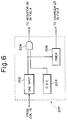
- Fig.6 shows a block diagram of a modified detector 20P incorporating a battery charging control feature.
- the detector 20P includes a one shot circuit 202 which generates a one shot pulse in response to the signal from the induction coil 19.
- the one shot pulse is supplied to a first input to AND gate 206.
- the AND gate 206 has a second input which receives clock signal pulses from an oscillator 204.
- the AND gate 206 outputs the clock signal pulses b during the period of one shot pulse.
- the output clock signal pulses b are supplied to the base of the transistor 33 (Fig.4) through the resistor 32.
- the one shot circuit 202 is also connected to a timer 208.
- the timer 208 measures the time interval between one shot pulses.
- the timer 208 starts time counting after receiving a one shot pulse.
- the timer 208 count at the time of receiving a one shot pulse indicates the time interval. If the time interval is relatively short, this means that the bicycle 11 is running at a relatively high speed. When the bicycle 11 speed is relatively slow, a relatively long time interval will be observed between one shot pulses.
- the timer 208 outputs a charging control signal a which is supplied to the charger 23 in Fig.4 for battery charging control.
- the charging control signal a When the timer 208 count is smaller than a predetermined value, indicating a relatively high speed of the bicycle 11, the charging control signal a enables the charger 23 to charge the battery 24 with electric energy induced in the coil 19. When the timer 208 count exceeds the predetermined value, indicating a relatively low speed of the bicycle 11, the charging control signal a is switched to inhibit the charger 23 from charging the battery 24.
Landscapes
- Engineering & Computer Science (AREA)
- Power Engineering (AREA)
- Secondary Cells (AREA)
- Electric Propulsion And Braking For Vehicles (AREA)
- Charge And Discharge Circuits For Batteries Or The Like (AREA)
Applications Claiming Priority (2)
| Application Number | Priority Date | Filing Date | Title |
|---|---|---|---|
| JP26172593A JP3567473B2 (ja) | 1993-09-24 | 1993-09-24 | 充電装置および走行体用コンピュータ |
| JP261725/93 | 1993-09-24 |
Publications (2)
| Publication Number | Publication Date |
|---|---|
| EP0645868A2 true EP0645868A2 (de) | 1995-03-29 |
| EP0645868A3 EP0645868A3 (de) | 1995-04-26 |
Family
ID=17365846
Family Applications (1)
| Application Number | Title | Priority Date | Filing Date |
|---|---|---|---|
| EP94115027A Withdrawn EP0645868A2 (de) | 1993-09-24 | 1994-09-23 | Ladegerät |
Country Status (2)
| Country | Link |
|---|---|
| EP (1) | EP0645868A2 (de) |
| JP (1) | JP3567473B2 (de) |
Cited By (9)
| Publication number | Priority date | Publication date | Assignee | Title |
|---|---|---|---|---|
| EP1244192A3 (de) * | 2001-03-22 | 2003-08-06 | Shimano Inc. | Fahrradbatterielader und Geschwindigkeitsmesserschaltung |
| EP1560185A2 (de) | 2004-01-21 | 2005-08-03 | Shimano Inc. | Selbstangetriebene Fahrradvorrichtung zur Ausgabe eines Signals und diese verwendenden Anzeigeapparat |
| EP1876510A3 (de) * | 2006-07-04 | 2011-07-27 | CAMPAGNOLO S.r.l. | Verfahren zur Steuerung und System zum Laden eines batteriebetriebenen Netzteils |
| EP1882999A3 (de) * | 2006-07-24 | 2011-07-27 | CAMPAGNOLO S.r.l. | Verfahren und System zum Wiederaufladen eines batteriebetriebenen Netzteils |
| US9018940B2 (en) | 2012-06-28 | 2015-04-28 | Shimano Inc. | Bicycle rotation detecting device |
| WO2016139617A1 (es) * | 2015-03-04 | 2016-09-09 | Juan Moya Saez | Sensor de giro y velocidad |
| US9634518B2 (en) | 2006-07-04 | 2017-04-25 | Campagnolo S.R.L. | Method and system for supplying electrical energy from a battery power supply unit to a heating element |
| CN107294282A (zh) * | 2017-07-27 | 2017-10-24 | 东南大学 | 一种基于法拉第电磁感应定律的自行车自发电装置 |
| CN108749982A (zh) * | 2018-04-18 | 2018-11-06 | 天津博众运动器材股份有限公司 | 一种手机充电用自行车前叉 |
Families Citing this family (3)
| Publication number | Priority date | Publication date | Assignee | Title |
|---|---|---|---|---|
| EP2805141B1 (de) * | 2012-04-09 | 2018-06-06 | Belon Engineering Inc. | Rotationssensor für ein pedal eines elektrisches fahrrads |
| KR20180045938A (ko) * | 2016-10-25 | 2018-05-08 | 한경대학교 산학협력단 | 자전거용 방향 지시 및 속도 표시 장치 |
| CN106839961A (zh) * | 2017-02-21 | 2017-06-13 | 南通市测绘院有限公司 | 一种快速测量卡距仪 |
Family Cites Families (6)
| Publication number | Priority date | Publication date | Assignee | Title |
|---|---|---|---|---|
| SE385408B (sv) * | 1973-03-21 | 1976-06-28 | Asea Ab | Sett att overvaka fyllnadsgraden i schakt o.d. for uppsamling av styckeformigt gods samt anordning for genomforande av settet |
| WO1981001274A1 (en) * | 1979-11-06 | 1981-05-14 | T Murphy | Bicycle or other vehicle generator improvement unit |
| DE3135380A1 (de) * | 1981-09-07 | 1983-03-17 | EMR-Elektronik GmbH, 7700 Singen | Verfahren und vorrichtung zum messen der laenge der fahrstrecke eines drehenden laufrades eines fahrzeuges und/oder von dessen geschwindigkeit |
| US5008647A (en) * | 1989-02-06 | 1991-04-16 | Orleander S.A. | Wireless bicycle wheel monitor system |
| RU1793227C (ru) * | 1990-12-21 | 1993-02-07 | Центральный научно-исследовательский институт технологии судостроения | Устройство дл определени параметров движени колесного транспортного средства с использованием мускульной силы |
| EP0516113A3 (en) * | 1991-05-31 | 1993-06-30 | Ppg Industries, Inc. | Disk mounting arrangement and wireless angular velocity detector |
-
1993
- 1993-09-24 JP JP26172593A patent/JP3567473B2/ja not_active Expired - Fee Related
-
1994
- 1994-09-23 EP EP94115027A patent/EP0645868A2/de not_active Withdrawn
Cited By (16)
| Publication number | Priority date | Publication date | Assignee | Title |
|---|---|---|---|---|
| EP1244192A3 (de) * | 2001-03-22 | 2003-08-06 | Shimano Inc. | Fahrradbatterielader und Geschwindigkeitsmesserschaltung |
| EP1422805A3 (de) * | 2001-03-22 | 2004-06-02 | Shimano Inc. | Fahrradbatterielader und Geschwindigkeitsmesserschaltung |
| USRE41015E1 (en) | 2001-03-22 | 2009-12-01 | Shimano, Inc. | Bicycle battery charger and speedometer circuit |
| EP1560185A2 (de) | 2004-01-21 | 2005-08-03 | Shimano Inc. | Selbstangetriebene Fahrradvorrichtung zur Ausgabe eines Signals und diese verwendenden Anzeigeapparat |
| EP1560185A3 (de) * | 2004-01-21 | 2007-08-01 | Shimano Inc. | Selbstangetriebene Fahrradvorrichtung zur Ausgabe eines Signals und diese verwendenden Anzeigeapparat |
| US7253610B2 (en) | 2004-01-21 | 2007-08-07 | Shimano, Inc. | Self-powered bicycle signal output device and display apparatus using same |
| US9469202B2 (en) | 2006-07-04 | 2016-10-18 | Campagnolo S.R.L. | Method for controlling and system for charging a battery power supply unit |
| CN101102054B (zh) * | 2006-07-04 | 2012-09-05 | 坎培诺洛有限公司 | 用于控制对电池供电单元充电的方法和系统 |
| EP1876510A3 (de) * | 2006-07-04 | 2011-07-27 | CAMPAGNOLO S.r.l. | Verfahren zur Steuerung und System zum Laden eines batteriebetriebenen Netzteils |
| US9634518B2 (en) | 2006-07-04 | 2017-04-25 | Campagnolo S.R.L. | Method and system for supplying electrical energy from a battery power supply unit to a heating element |
| EP1882999A3 (de) * | 2006-07-24 | 2011-07-27 | CAMPAGNOLO S.r.l. | Verfahren und System zum Wiederaufladen eines batteriebetriebenen Netzteils |
| US8143849B2 (en) | 2006-07-24 | 2012-03-27 | Campagnolo S.R.L. | Method and system for recharging a battery power supply unit for a bicycle electronic device |
| US9018940B2 (en) | 2012-06-28 | 2015-04-28 | Shimano Inc. | Bicycle rotation detecting device |
| WO2016139617A1 (es) * | 2015-03-04 | 2016-09-09 | Juan Moya Saez | Sensor de giro y velocidad |
| CN107294282A (zh) * | 2017-07-27 | 2017-10-24 | 东南大学 | 一种基于法拉第电磁感应定律的自行车自发电装置 |
| CN108749982A (zh) * | 2018-04-18 | 2018-11-06 | 天津博众运动器材股份有限公司 | 一种手机充电用自行车前叉 |
Also Published As
| Publication number | Publication date |
|---|---|
| JP3567473B2 (ja) | 2004-09-22 |
| EP0645868A3 (de) | 1995-04-26 |
| JPH0794213A (ja) | 1995-04-07 |
Similar Documents
| Publication | Publication Date | Title |
|---|---|---|
| EP0645868A2 (de) | Ladegerät | |
| US5511435A (en) | Apparatus for measuring vehicle running condition | |
| US5623193A (en) | Apparatus for controlling battery discharge | |
| JPH0321447Y2 (de) | ||
| JPS60118713U (ja) | 自転車用走行データ表示装置 | |
| JP2593132B2 (ja) | 電池作動式装置 | |
| US11794600B2 (en) | Vehicle and control method of vehicle | |
| US5740132A (en) | Electronic timepiece and method of charging the same | |
| US10697793B2 (en) | Hub-mountable wheel-rotation detector | |
| JP3475458B2 (ja) | 走行状態検出装置および走行状態検出用受信機 | |
| JP2018083529A (ja) | 電動補助自転車および電動補助自転車のバッテリ状態監視方法 | |
| JP4190965B2 (ja) | タイヤモニタ装置 | |
| US4807265A (en) | Recreation vehicle distance measuring device | |
| JPH1138161A5 (de) | ||
| JP2005178425A (ja) | タイヤ空気圧検出装置 | |
| WO2019069337A1 (en) | PROGRAMMABLE AND REMOTELY CONTROLLED SAFETY PEDAL FOR BICYCLE | |
| JPH07229909A (ja) | 自転車のスピードメーター | |
| JPH0717450A (ja) | 走行状態検出装置 | |
| US4879732A (en) | Odometer with distance traveled and distance remaining displays | |
| RU1793227C (ru) | Устройство дл определени параметров движени колесного транспортного средства с использованием мускульной силы | |
| JPS6052641B2 (ja) | 電気自動車における走行情報表示装置 | |
| JPH10304502A (ja) | アシスト走行可能距離表示装置 | |
| JP4198818B2 (ja) | タイヤ回転数測定装置 | |
| HK1013435B (en) | Apparatus for measuring vehicle running condition | |
| JP2933052B2 (ja) | マイクロロボット |
Legal Events
| Date | Code | Title | Description |
|---|---|---|---|
| PUAI | Public reference made under article 153(3) epc to a published international application that has entered the european phase |
Free format text: ORIGINAL CODE: 0009012 |
|
| PUAL | Search report despatched |
Free format text: ORIGINAL CODE: 0009013 |
|
| 17P | Request for examination filed |
Effective date: 19940923 |
|
| AK | Designated contracting states |
Kind code of ref document: A2 Designated state(s): DE FR GB |
|
| AK | Designated contracting states |
Kind code of ref document: A3 Designated state(s): DE FR GB |
|
| 18D | Application deemed to be withdrawn |
Effective date: 19951027 |