EP0646068B1 - Gleitschutzstift - Google Patents
Gleitschutzstift Download PDFInfo
- Publication number
- EP0646068B1 EP0646068B1 EP92900137A EP92900137A EP0646068B1 EP 0646068 B1 EP0646068 B1 EP 0646068B1 EP 92900137 A EP92900137 A EP 92900137A EP 92900137 A EP92900137 A EP 92900137A EP 0646068 B1 EP0646068 B1 EP 0646068B1
- Authority
- EP
- European Patent Office
- Prior art keywords
- tip
- skid stud
- skid
- stud
- tip part
- Prior art date
- Legal status (The legal status is an assumption and is not a legal conclusion. Google has not performed a legal analysis and makes no representation as to the accuracy of the status listed.)
- Expired - Lifetime
Links
- 239000000463 material Substances 0.000 claims description 10
- 239000011800 void material Substances 0.000 claims description 4
- 239000011162 core material Substances 0.000 claims 1
- 229910000831 Steel Inorganic materials 0.000 description 5
- 239000010959 steel Substances 0.000 description 5
- 239000002184 metal Substances 0.000 description 4
- 230000001133 acceleration Effects 0.000 description 3
- 238000005096 rolling process Methods 0.000 description 3
- 229910010293 ceramic material Inorganic materials 0.000 description 1
- 230000004313 glare Effects 0.000 description 1
- 239000003562 lightweight material Substances 0.000 description 1
- 239000004033 plastic Substances 0.000 description 1
Images
Classifications
-
- B—PERFORMING OPERATIONS; TRANSPORTING
- B60—VEHICLES IN GENERAL
- B60C—VEHICLE TYRES; TYRE INFLATION; TYRE CHANGING; CONNECTING VALVES TO INFLATABLE ELASTIC BODIES IN GENERAL; DEVICES OR ARRANGEMENTS RELATED TO TYRES
- B60C11/00—Tyre tread bands; Tread patterns; Anti-skid inserts
- B60C11/14—Anti-skid inserts, e.g. vulcanised into the tread band
- B60C11/16—Anti-skid inserts, e.g. vulcanised into the tread band of plug form, e.g. made from metal, textile
-
- B—PERFORMING OPERATIONS; TRANSPORTING
- B60—VEHICLES IN GENERAL
- B60C—VEHICLE TYRES; TYRE INFLATION; TYRE CHANGING; CONNECTING VALVES TO INFLATABLE ELASTIC BODIES IN GENERAL; DEVICES OR ARRANGEMENTS RELATED TO TYRES
- B60C11/00—Tyre tread bands; Tread patterns; Anti-skid inserts
- B60C11/14—Anti-skid inserts, e.g. vulcanised into the tread band
- B60C11/16—Anti-skid inserts, e.g. vulcanised into the tread band of plug form, e.g. made from metal, textile
- B60C11/1643—Anti-skid inserts, e.g. vulcanised into the tread band of plug form, e.g. made from metal, textile with special shape of the plug-body portion, i.e. not cylindrical
- B60C11/1656—Anti-skid inserts, e.g. vulcanised into the tread band of plug form, e.g. made from metal, textile with special shape of the plug-body portion, i.e. not cylindrical concave or convex, e.g. barrel-shaped
Definitions
- This invention relates to anti-skid studs as specified in the preamble of Claim 1.
- anti-skid studs are well known from the state of the art.
- Anti-skid studs for vehicle tires are largely based on the principle of a spike projecting out from the tire and being made up of a thin hard-metal stud, 2 - 3 mm in diameter, which is surrounded in a varying manner by metal or plastic or by a combination of the two. All of them have the disadvantage that the small hard-metal tip subjects the road to a relatively high surface pressure, which wears an ice-free road, and that, on the other hand, its grip is very poor on a thin so-called black ice surface, which the tip of the stud cannot penetrate. As a result, a stud, rounded by wear, will skate on the ice surface, with a friction coefficient even lower than that of rubber.
- an anti-skid stud according to the present invention reduces the disadvantages referred to above.
- an anti-skid stud in accordance with the present invention is characterised by the features specified in the characterising part of Claim 1.
- a special embodiment is claimed in Claim 2.
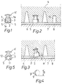
- An anti-skid stud according to the invention is characterised in that the fastening flanged (15) anti-skid stud ( Figures 1 and 5), installed in a vehicle tire in a conventional manner, has no conventional hard-metal pin; the anti-skid tip 1 of the stud has in the gripping area 5 a diameter (in general 5... 12 mm) which is large in comparison with the total length of the anti-skid stud.
- the tip of the stud constitutes a concave or straight surface 2, in which case its road contact is primarily annular and wide when the stud is in its basic position perpendicular to the road surface ( Figure 2). Owing to the width of the contact area, the surface pressure against the road is relatively low.
- the core part, i.e. the body material 1a, of the anti-skid stud is not so hard as its mantle surface 3, and this prevents the tip 2 of the stud from obtaining a convex shape as the stud wears down.
- Anti-skid studs according to the invention are placed in a vehicle tire in a conventional manner, installed in bed-holes 10 prepared in advance in the tire tread rubber 4 ( Figure 2), i.e. around the whole tire, in a suitable number, usually the maximum number permitted in the regulations. Unloaded, the annular tip 5 of the anti-skid stud protrudes somewhat from the surface 6 of the vehicle tire. In Figure 2 the tire is pressed by the weight of the vehicle against the ice surface 8 on the road surface 7, whereupon the annular tip 5 of the anti-skid stud will penetrate somewhat into the ice surface 8. When the vehicle is travelling, without acceleration or braking, on a road covered with glare ice, the anti-skid stud is in its stand-by position in accordance with Figure 2.
- the anti-skid stud according to Figure 1 is made of a material which can be processed so as to be hard on its surface, for example of cemented steel with a cementation depth of approx. 1 mm and a surface hardness of over 800 HV within the area 3, the core part 1a which will wear into a concave shape remaining softer.
- the tip part 2 which will wear so as to obtain a concave shape can be left uncemented, in which case it will initially operate as a straight plane and will gradually wear into a concave shape, or it can be machined into a concave shape after the cementation.
- an anti-skid stud thus made is somewhat heavier than conventional studs, owing to its greater exterior diameter, its road-wearing action is considerably less than that of conventional studs, owing to the considerably lower surface pressure against the road surface during normal rolling. However, in a skid situation the grip against the road is good.
- the material of the anti-skid stud may also be some other material which can be processed to be hard on its exterior surface but is lighter than cemented steel.
- an anti-skid stud according to Figure 5 made of a suitably hard material or of a material which can be processed so as to be hard, the concavity 2 in Figure 1 has been replaced by a void 11, which will maintain the straightness of the tip 5 and its annular contact with the road surface during rolling.
- a void 11 which will maintain the straightness of the tip 5 and its annular contact with the road surface during rolling.
- rapid steel, cemented steel, and various ceramic materials are suitable materials.
- the weight of an anti-skid stud made of cemented steel may be reduced and the hardest possible cementation is obtained for almost all of the material 12 coming into contact with the road, as cementation also takes place inside the void 11.
- the void 11 may, when necessary, be filled up with some lightweight material softer than the material 12.
Landscapes
- Mechanical Engineering (AREA)
- Engineering & Computer Science (AREA)
- Tires In General (AREA)
- Regulating Braking Force (AREA)
- Organic Low-Molecular-Weight Compounds And Preparation Thereof (AREA)
- Saccharide Compounds (AREA)
- Polishing Bodies And Polishing Tools (AREA)
- Devices For Conveying Motion By Means Of Endless Flexible Members (AREA)
- Valve-Gear Or Valve Arrangements (AREA)
- Braking Arrangements (AREA)
- Electrical Discharge Machining, Electrochemical Machining, And Combined Machining (AREA)
- Polymers With Sulfur, Phosphorus Or Metals In The Main Chain (AREA)
- Luminescent Compositions (AREA)
Claims (2)
- Gleitschutzstift, der mit einem Befestigungsflansch (15) versehen ist, um auf herkömmliche Weise in einer im voraus in der Lauffläche eines Fahrzeugreifens hergestellten Einbettungsöffnung (10) eingebracht zu werden, dadurch gekennzeichnet, daß das vordere Ende (2) des vorderen Teils (1) gleichen oder etwas kleineren Durchmesser als der Befestigungsflansch des Gleitschutzstiftes aufweist, flach oder konkav ist, und daß die Haftung des Gleitschutzstiftes auf einer glatten Straßenoberfläche (8) dann auftritt, wenn die Kante (5) des vorderen Endes (2) des Gleitschutzstiftes von der Oberfläche (6) des Fahrzeugreifens in größerem Ausmaß als in seiner Bereitschaftsposition (Figur 2) vorragt wenn der Gleitschutzstift kippt, beispielsweise unter Einwirkung einer äußeren Kraft (P) beim Bremsen, woraufhin die vorragende Kante (5) des vorderen Teil eine breiten (B in Figur 4) Haftung, tiefer (H in Figur 3) als bei der Bereitschaftsposition des Stiftes, auf der eisigen Straßenoberfläche erzeugt.
- Gleitschutzstift nach Anspruch 1, dadurch gekennzeichnet, daß beim Gleitschutzstift der mittlere Teil jenes Bereiches des Gleitschutzvorderteils (1), welcher in Berührung mit der Straßenoberfläche kommt, mit einer Ausnehmung (11) versehen ist, um zu verhindern, daß das vordere Ende beim Verschleiß eine konvexe Form annimmt, oder daß die Manteloberfläche (3) des vorderen Teils (1) bis zu einer geeigneten Tiefe aus einem Material besteht, das verschleißfester, d.h. in erster Linie härter, als das Kernmaterial des vorderen Teils (1) ist, wobei das vordere Ende des vorderen Teils, wenn es derart ausgeführt ist, unter der Verschleißeinwirkung beim Fahren keine konvexe Gestalt annimmt, sondern an seiner Oberfläche (2) eine konkave Gestalt annimmt oder beinahe flach bleibt.
Applications Claiming Priority (3)
| Application Number | Priority Date | Filing Date | Title |
|---|---|---|---|
| FI906197A FI89688C (fi) | 1990-12-14 | 1990-12-14 | Slirskydd |
| FI906197 | 1990-12-14 | ||
| PCT/FI1991/000383 WO1992010374A1 (en) | 1990-12-14 | 1991-12-12 | Anti-skid stud |
Publications (2)
| Publication Number | Publication Date |
|---|---|
| EP0646068A1 EP0646068A1 (de) | 1995-04-05 |
| EP0646068B1 true EP0646068B1 (de) | 1997-06-04 |
Family
ID=8531583
Family Applications (1)
| Application Number | Title | Priority Date | Filing Date |
|---|---|---|---|
| EP92900137A Expired - Lifetime EP0646068B1 (de) | 1990-12-14 | 1991-12-12 | Gleitschutzstift |
Country Status (9)
| Country | Link |
|---|---|
| EP (1) | EP0646068B1 (de) |
| JP (1) | JPH06503284A (de) |
| AT (1) | ATE153925T1 (de) |
| CA (1) | CA2098318C (de) |
| DE (1) | DE69126448T2 (de) |
| EE (1) | EE03080B1 (de) |
| FI (1) | FI89688C (de) |
| RU (1) | RU2093368C1 (de) |
| WO (1) | WO1992010374A1 (de) |
Families Citing this family (2)
| Publication number | Priority date | Publication date | Assignee | Title |
|---|---|---|---|---|
| WO1996028310A1 (en) * | 1995-03-10 | 1996-09-19 | Taiti Oy | Stud |
| JP5196115B2 (ja) * | 2007-07-23 | 2013-05-15 | 横浜ゴム株式会社 | 空気入りタイヤ |
Family Cites Families (2)
| Publication number | Priority date | Publication date | Assignee | Title |
|---|---|---|---|---|
| US3179147A (en) * | 1963-03-15 | 1965-04-20 | Sandvikens Jernverks Ab | Traction-augmenting stud for a vehicle tire |
| FI82907C (fi) * | 1988-01-22 | 1991-05-10 | Neste Oy | Fast dubb, motsvarande holkdubb, avsedd foer ett fordonsdaeck. |
-
1990
- 1990-12-14 FI FI906197A patent/FI89688C/fi active IP Right Grant
-
1991
- 1991-12-12 AT AT92900137T patent/ATE153925T1/de not_active IP Right Cessation
- 1991-12-12 CA CA002098318A patent/CA2098318C/en not_active Expired - Fee Related
- 1991-12-12 EP EP92900137A patent/EP0646068B1/de not_active Expired - Lifetime
- 1991-12-12 WO PCT/FI1991/000383 patent/WO1992010374A1/en not_active Ceased
- 1991-12-12 JP JP4500399A patent/JPH06503284A/ja active Pending
- 1991-12-12 RU RU9193046321A patent/RU2093368C1/ru not_active IP Right Cessation
- 1991-12-12 DE DE69126448T patent/DE69126448T2/de not_active Expired - Fee Related
-
1994
- 1994-11-23 EE EE9400355A patent/EE03080B1/xx not_active IP Right Cessation
Also Published As
| Publication number | Publication date |
|---|---|
| JPH06503284A (ja) | 1994-04-14 |
| FI906197L (fi) | 1992-06-15 |
| DE69126448T2 (de) | 1997-09-25 |
| WO1992010374A1 (en) | 1992-06-25 |
| ATE153925T1 (de) | 1997-06-15 |
| EE03080B1 (et) | 1998-04-15 |
| EP0646068A1 (de) | 1995-04-05 |
| FI906197A0 (fi) | 1990-12-14 |
| CA2098318C (en) | 2003-02-18 |
| RU2093368C1 (ru) | 1997-10-20 |
| CA2098318A1 (en) | 1992-06-15 |
| FI89688C (fi) | 1993-11-10 |
| DE69126448D1 (de) | 1997-07-10 |
| FI89688B (fi) | 1993-07-30 |
Similar Documents
| Publication | Publication Date | Title |
|---|---|---|
| US12083829B2 (en) | Three-dimensional tire sipe | |
| US6484772B1 (en) | Tread pattern and method of manufacture | |
| US4186823A (en) | Wheel wedge | |
| AU766391B2 (en) | Tire having sacrificial bridging | |
| CA2170797C (en) | Vehicle tyre that can be elastically fitted with studs | |
| NZ232623A (en) | Heavy vehicle speed-endurance radial tyre tread: inclined transverse incisions in ribs | |
| EP0342908A2 (de) | Luftreifen | |
| EP0810104A1 (de) | Reifenlauffläche mit Feineinschnitten in den elastomerischen Profilblöcken | |
| JPH08324211A (ja) | 空気入りタイヤ | |
| JPH1199810A (ja) | 雪路用空気入りタイヤ | |
| EP1241026A3 (de) | Reifen, Vorrichtung zum Extrudieren eines unvulkanisierten Reifenlaufflächengummis, und Verfahren zum Extrudieren desselben | |
| US5634994A (en) | Anti-skid stud | |
| WO2009068744A1 (en) | Anti-skid stud for a tyre | |
| CA2098318C (en) | Anti-skid stud | |
| US3426822A (en) | Tire stud | |
| EP0540339B1 (de) | Luftreifen | |
| CA1284087C (en) | Sleeve-mounted spike fitted on a vehicle tyre | |
| JPH05319028A (ja) | 重荷重用空気入りラジアルタイヤ | |
| EP1304239A2 (de) | Lauffläche für einen LKW-Reifen | |
| WO1992013729A1 (en) | Anti-skid stud | |
| WO1996028310A1 (en) | Stud | |
| JPH0683402U (ja) | 冬用タイヤ | |
| JP2816853B2 (ja) | 空気入りラジアルタイヤ | |
| EP2285597B1 (de) | Anti-rutsch-noppen und fahrzeugreifen | |
| JPH07266809A (ja) | 空気入りラジアルタイヤ |
Legal Events
| Date | Code | Title | Description |
|---|---|---|---|
| PUAI | Public reference made under article 153(3) epc to a published international application that has entered the european phase |
Free format text: ORIGINAL CODE: 0009012 |
|
| 17P | Request for examination filed |
Effective date: 19930614 |
|
| AK | Designated contracting states |
Kind code of ref document: A1 Designated state(s): AT CH DE FR GB LI SE |
|
| 17Q | First examination report despatched |
Effective date: 19950606 |
|
| GRAG | Despatch of communication of intention to grant |
Free format text: ORIGINAL CODE: EPIDOS AGRA |
|
| GRAH | Despatch of communication of intention to grant a patent |
Free format text: ORIGINAL CODE: EPIDOS IGRA |
|
| RAP1 | Party data changed (applicant data changed or rights of an application transferred) |
Owner name: TAITI OY |
|
| RIN1 | Information on inventor provided before grant (corrected) |
Inventor name: TEERI, NIILO HEIKKI |
|
| GRAH | Despatch of communication of intention to grant a patent |
Free format text: ORIGINAL CODE: EPIDOS IGRA |
|
| GRAA | (expected) grant |
Free format text: ORIGINAL CODE: 0009210 |
|
| AK | Designated contracting states |
Kind code of ref document: B1 Designated state(s): AT CH DE FR GB LI SE |
|
| REF | Corresponds to: |
Ref document number: 153925 Country of ref document: AT Date of ref document: 19970615 Kind code of ref document: T |
|
| REG | Reference to a national code |
Ref country code: CH Ref legal event code: EP |
|
| REF | Corresponds to: |
Ref document number: 69126448 Country of ref document: DE Date of ref document: 19970710 |
|
| ET | Fr: translation filed | ||
| REG | Reference to a national code |
Ref country code: CH Ref legal event code: NV Representative=s name: BUECHEL, VON REVY & PARTNER |
|
| PLBE | No opposition filed within time limit |
Free format text: ORIGINAL CODE: 0009261 |
|
| STAA | Information on the status of an ep patent application or granted ep patent |
Free format text: STATUS: NO OPPOSITION FILED WITHIN TIME LIMIT |
|
| 26N | No opposition filed | ||
| PGFP | Annual fee paid to national office [announced via postgrant information from national office to epo] |
Ref country code: CH Payment date: 20011217 Year of fee payment: 11 |
|
| PGFP | Annual fee paid to national office [announced via postgrant information from national office to epo] |
Ref country code: AT Payment date: 20011220 Year of fee payment: 11 |
|
| REG | Reference to a national code |
Ref country code: GB Ref legal event code: IF02 |
|
| PG25 | Lapsed in a contracting state [announced via postgrant information from national office to epo] |
Ref country code: AT Free format text: LAPSE BECAUSE OF NON-PAYMENT OF DUE FEES Effective date: 20021212 |
|
| PG25 | Lapsed in a contracting state [announced via postgrant information from national office to epo] |
Ref country code: LI Free format text: LAPSE BECAUSE OF NON-PAYMENT OF DUE FEES Effective date: 20021231 Ref country code: CH Free format text: LAPSE BECAUSE OF NON-PAYMENT OF DUE FEES Effective date: 20021231 |
|
| REG | Reference to a national code |
Ref country code: CH Ref legal event code: PL |
|
| PGFP | Annual fee paid to national office [announced via postgrant information from national office to epo] |
Ref country code: FR Payment date: 20061130 Year of fee payment: 16 |
|
| PGFP | Annual fee paid to national office [announced via postgrant information from national office to epo] |
Ref country code: SE Payment date: 20061212 Year of fee payment: 16 |
|
| PGFP | Annual fee paid to national office [announced via postgrant information from national office to epo] |
Ref country code: DE Payment date: 20061219 Year of fee payment: 16 |
|
| PGFP | Annual fee paid to national office [announced via postgrant information from national office to epo] |
Ref country code: GB Payment date: 20061221 Year of fee payment: 16 |
|
| EUG | Se: european patent has lapsed | ||
| GBPC | Gb: european patent ceased through non-payment of renewal fee |
Effective date: 20071212 |
|
| PG25 | Lapsed in a contracting state [announced via postgrant information from national office to epo] |
Ref country code: SE Free format text: LAPSE BECAUSE OF NON-PAYMENT OF DUE FEES Effective date: 20071213 Ref country code: DE Free format text: LAPSE BECAUSE OF NON-PAYMENT OF DUE FEES Effective date: 20080701 |
|
| REG | Reference to a national code |
Ref country code: FR Ref legal event code: ST Effective date: 20081020 |
|
| PG25 | Lapsed in a contracting state [announced via postgrant information from national office to epo] |
Ref country code: GB Free format text: LAPSE BECAUSE OF NON-PAYMENT OF DUE FEES Effective date: 20071212 |
|
| PG25 | Lapsed in a contracting state [announced via postgrant information from national office to epo] |
Ref country code: FR Free format text: LAPSE BECAUSE OF NON-PAYMENT OF DUE FEES Effective date: 20071231 |