EP0646349A2 - Sonde d'imagerie ultrasonore - Google Patents
Sonde d'imagerie ultrasonore Download PDFInfo
- Publication number
- EP0646349A2 EP0646349A2 EP94110438A EP94110438A EP0646349A2 EP 0646349 A2 EP0646349 A2 EP 0646349A2 EP 94110438 A EP94110438 A EP 94110438A EP 94110438 A EP94110438 A EP 94110438A EP 0646349 A2 EP0646349 A2 EP 0646349A2
- Authority
- EP
- European Patent Office
- Prior art keywords
- probe
- transducer
- ultrasonic imaging
- holder
- imaging probe
- Prior art date
- Legal status (The legal status is an assumption and is not a legal conclusion. Google has not performed a legal analysis and makes no representation as to the accuracy of the status listed.)
- Granted
Links
Images

Classifications
-
- A—HUMAN NECESSITIES
- A61—MEDICAL OR VETERINARY SCIENCE; HYGIENE
- A61B—DIAGNOSIS; SURGERY; IDENTIFICATION
- A61B8/00—Diagnosis using ultrasonic, sonic or infrasonic waves
- A61B8/06—Measuring blood flow
-
- A—HUMAN NECESSITIES
- A61—MEDICAL OR VETERINARY SCIENCE; HYGIENE
- A61B—DIAGNOSIS; SURGERY; IDENTIFICATION
- A61B8/00—Diagnosis using ultrasonic, sonic or infrasonic waves
- A61B8/12—Diagnosis using ultrasonic, sonic or infrasonic waves in body cavities or body tracts, e.g. by using catheters
-
- A—HUMAN NECESSITIES
- A61—MEDICAL OR VETERINARY SCIENCE; HYGIENE
- A61B—DIAGNOSIS; SURGERY; IDENTIFICATION
- A61B8/00—Diagnosis using ultrasonic, sonic or infrasonic waves
- A61B8/44—Constructional features of the ultrasonic, sonic or infrasonic diagnostic device
- A61B8/4444—Constructional features of the ultrasonic, sonic or infrasonic diagnostic device related to the probe
- A61B8/445—Details of catheter construction
-
- A—HUMAN NECESSITIES
- A61—MEDICAL OR VETERINARY SCIENCE; HYGIENE
- A61B—DIAGNOSIS; SURGERY; IDENTIFICATION
- A61B8/00—Diagnosis using ultrasonic, sonic or infrasonic waves
- A61B8/44—Constructional features of the ultrasonic, sonic or infrasonic diagnostic device
- A61B8/4444—Constructional features of the ultrasonic, sonic or infrasonic diagnostic device related to the probe
- A61B8/4461—Features of the scanning mechanism, e.g. for moving the transducer within the housing of the probe
Definitions
- This invention generally relates to ultrasonic intravascular imaging devices -- i.e., devices of the type which utilize acoustic transducers operating at ultrasonic frequencies to image intravascular geometry and/or associated tissue characteristics.
- it includes an elongate probe guide assembly, an ultrasonic transducer fixed to the probe guide assembly's distal end, and electrical cabling housed within, and extending proximally of, the probe guide assembly so as to send/receive electrical signals to/from the transducer.
- This invention effectively reduces "dead space” radially of the probe otherwise obscuring nearby reflections during the normal "ring down" time of a piezoelectric transceiver/transducer immediately after a transmit operation.
- a reflector is distally spaced from the transducer so as to reflect the ultrasound waves between a first path which is substantially parallel to the probe axis and a second path which is substantially perpendicular (i.e., radial) to the probe axis.
- a tuning induction coil is electrically connected in series with the transducer and is coaxially positioned within the tube section closely adjacent to the transducer. Such structure permits the ultrasound probes of this invention to be sufficiently miniaturized to be useful in extremely near-field intravascular imaging procedures.
- Intravascular probes which include ultrasound imaging crystal arrays have been proposed in the past. It is known, for example, to mount a piezoelectric crystal element (conventionally termed a "transducer") on or within a catheter of the type which can be inserted into a blood vessel. Once the probe has been inserted into a blood vessel, the transducer is electro-mechanically excited (as by the application of an electrical signal) to cause emission of ultrasonic energy into the surrounding tissue.
- a piezoelectric crystal element conventionally termed a "transducer”
- the transducer is electro-mechanically excited (as by the application of an electrical signal) to cause emission of ultrasonic energy into the surrounding tissue.
- the transducer in turn, produces weak electrical signals in response to electro mechanical excitation by the returning reflected ("echo") ultrasonic energy.
- These weak electrical signals can be used to determine the geometry and/or other characteristics of the blood vessel, for example, to determine whether or not the blood vessel contains lesions or other abnormalities.
- imaging suitable video and/or other signal monitoring equipment are employed to convert the weak electrical signals produced by the transducer into human-readable form. Information gained from such imaging thus may assist the physician in a vascular treatment in real time or in diagnosing a patient's particular ailment or disease so that suitable therapy can be prescribed.
- the ultrasonic imaging probe consists of a commercially available elongate probe guide assembly made of polyvinyl chloride.
- This ultrasonic imaging probe features a cylindrical ultrasonic transducer array of six elements for detecting lumen area together with a single transducer for detecting blood velocity, both located at the tip of the probe and mounted within a holder.
- This holder is connected to an axially distal end of the probe guide assembly by connecting means.
- Electrical cable means are operatively connected to the transducers for transmitting electrical signals to, and for receiving electrical signals from the transducers.
- the ultrasound propagates in radial direction of the transducers and is reflected by the object to be imaged or measured, respectively.
- ring down time will inherently be present so that a region surrounding the transducer is effectively masked -- that is to say, the ring down time creates a "dead space" in the immediate vicinity of the transducer where no imaging is possible.
- transducer dead space The dimensional extent of such dead space is dependant upon many variables, including the frequency of operation of the transducer. Suffice it to say here that although transducer dead space can be tolerated when relatively large intravascular cavities are imaged (i.e., relative to the size of the imaging probe), significant problems are encountered when small intravascular cavities, such as small diameter blood vessels, etcetera, are to be imaged. And, in any event, transducer dead space mitigates against miniaturization since even the smallest diameter imaging probe is only capable of imaging intravascular cavities outside of its surrounding dead space, thereby providing for an effective imaging area which is usually only significantly greater than the probe's diameter.
- transducer must be "tuned” to the electrical cabling which supplies driving signals to, and returns weaker echo electrical signals from, the transducer. That is, since the transducer, at its frequency of operation, exhibits a net capacitive reactance, inductive reactance should be provided so as to efficiently couple the transmit/receive signals to the transducer (e.g., so as to maximize signal-to-noise ratios).
- the present invention provides a miniaturized ultrasonic imaging probe which not only exhibits essentially zero "dead space" (i.e., intravascular imaging can be accomplished in blood vessels having, or capable of being dilated to, substantially the same diameter as the probe itself) but also provides for internal (i.e., as part of the probe per se) inductive reactance. And, the fact that internal inductive reactance may now be provided enhances the ability to use weak electrical echo signals for purposes of diagnostic imaging.
- an ultrasonic imaging probe of the type including a probe guide assembly, a transducer connected to the distal end of the probe guide assembly, and electrical cabling housed within the probe guide assembly and operatively connected to the transducer for transmitting electrical power to, and receiving electrical signals from, the transducer.
- the transducer is mounted within a proximal end portion of a generally cylindrical holder (itself being attached to the distal end of the probe guide assembly) which defines an elongate, open trough.
- the transducer is also mounted near the proximal end of the trough.
- An ultrasound reflector (e.g., polished stainless steel) is mounted at the distal end of the holder (i.e., at the distal end of the defined trough) in axially spaced relation to the transducer for directing ultrasonic energy waves between a first path (which is substantially parallel to the elongate axis of the probe) to a second path (which is substantially perpendicular to the elongate axis of the probe).
- a first path which is substantially parallel to the elongate axis of the probe
- second path which is substantially perpendicular to the elongate axis of the probe.
- Echo waves which radially return from the surrounding tissue will likewise be redirected by means of the reflector axially of the probe towards the transducer.
- the distance that the reflector is axially spaced from the transducer is selected such that the "dead space" lies substantially therebetween.
- the probe of the invention is also provided with an inductor coil as the inductive reactance, the inductor coil being coaxially housed within the probe guide assembly and positioned closely adjacent the transducer.
- the electrical cabling of the invention is a standard coaxial cable having an inner conductor (with an associated insulating layer) and an annular outer conductor (with an associated insulating layer).
- a distal end segment of the outer conductor (and its associated insulating layer) is removed.
- the inductor coil is then coaxially positioned over the inner conductor (and its associated insulating layer) in the space previously occupied by the removed outer conductor segment.
- the proximal end of the inductor coil is thus connected to the distal end of the remaining outer conductor while the distal end of the inductor coil is connected electrically to the transducer.
- the inner conductor is connected electrically to the transducer at a location different from the connection of the inductor coil (preferably at a location on the front face of the transducer). In such a manner, the transducer and inductor coil are connected closely adjacent, and in series relationship, to one another.
- System 10 generally includes an ultrasound imaging probe 12 (which will be described in greater detail below) generally comprised of proximal probe guide assembly 14, an ultrasound "bullet” 16 (i.e., structure which includes the ultrasound transducer), and a distal guidewire assembly 18.
- a visual position indicator and rotation knob 20 are operatively associated with the probe 12 so as to assist the physician in his/her intravascular manipulation and positioning of the bullet 16.
- An ultrasound transmitter/receiver 24 is connected to a preamplifier 26 via standard coaxial cable 28.
- the transmitter/receiver 24 is of a conventional type in that it produces a pulse signal (of a desired magnitude and shape) which is applied via cable 28 and preamplifier 26 to excite an elec- troacoustic transducer housed within bullet 16.
- the receiver portion of transmitter/receiver 24 performs conventional signal processing operations (e.g., amplification, noise reduction and the like) on electrical signals generated by electro mechanical excitation of the transducer within bullet 16 (i.e., signals generated by the transducer in response to receiving echo waves), which signals have been amplified via preamplifier 26.
- These processed signals are then supplied as an input to a CRT 20 monitor (or any other equivalent display device) so as to generate an ultrasound image 30 representative of the vascular structures reflecting ultrasonic energy toward the transducer within bullet 16 using, for example, conventional PPI (radar) algorithms.
- a CRT 20 monitor or any other equivalent display device
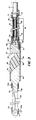
- the imaging probe 12 of this invention is shown more clearly in accompanying FIGURES 2 and 3 in a greatly enlarged manner for clarity of presentation.
- the probe 12 can be of any desired length, it preferably is fabricated to a length of about 60 inches having a nominal diameter of about .0038 inch.
- the probe guide assembly 14 is currently comprised of a coaxial cable 28 housed within the lumen 32 (see FIGURE 3) of a tube section 33 so as to transmit electrical pulses to, and return electrical signals from, the transducer 34 housed within the bullet 16.
- the bullet 16 is itself comprised of a one-piece holder 36 which defines an axially elongate open trough 38.
- the holder 36 thus houses the transducer 34 within its proximal end so that the front face 40 of transducer 34 extends slightly beyond the proximal end 42 of trough 38.
- the other, distal end of holder 36 houses an acoustic reflector 44 (whose functions will be described in greater detail below) which in the preferred embodiment shown, defines a beveled planar surface 46 oriented at an angle (e.g., 450) relative to the longitudinal axis 48 of probe 12.
- the surface 46 of reflector 44 may, however, be concave, particularly if convergent focussing of emit- ted/returned echo waves is desired. In either case, the angular orientation of surface 46 with respect to a transverse plane may be greater/lesser than 45 ° so as to project the reflected acoustic waves in a proximal/distal direction, respectively.
- the acoustic reflector 44 and holder 36 are each preferably fabricated from stainless steel and are rigidly coupled to one another via soldering, welding or like techniques.
- the transducer 34 is rigidly maintained within holder 36 via a suitable biocompatible adhesive.
- transducer 34 and reflector 44 within holder 36 could, however, be reversed from that shown in the accompanying FIGURES, if desired.
- transducer 34 could occupy the distal end of holder 36 while reflector 44 could occupy the proximal end of holder 36.
- the open trough 38 is filled with a solid acoustic couplant 49 which is shown only in FIGURE 3 for clarity of presentation.
- Acoustic couplant 49 can be any suitable minimally acoustic-absorbant polymer material such as low density polyethlene, polyurethane, and the like.
- Couplant 49 thus exhibits an acoustic impedence which is closely matched to that of transducer 34 and the patient's blood.
- the acoustic couplant 49 also presents an overall smooth cylindrical exterior surface to holder 36 which is beneficial since the holder 36 may then be more easily manipulated within a patient's arterial tissue. Because it fills the trough 38, the acousic couplant 49 prevents blood from pooling and clotting within holder 36, which clotting could cause patient thrombosis.
- the distal guidewire assembly 18 is comprised of a coiled guidewire 50 (e.g., formed from about .003 in. diameter wire and tightly coiled to an outside diameter of about .038 in.) having its proximal end 50a rigidly coupled to the holder/reflector 36/44 as by soldering, welding or the like.
- a tip 52 of a noble metal e.g., gold, platinum or the like
- Tip 52 presents a smooth convex surface to more easily facilitate intravascular maneuvering. Also, since the tip 52 is formed of a noble metal, it is visible when fluoroscopic techniques are employed.
- the tip 52 also embeds the distal end of a continuous safety ribbon 54.
- the proximate end of ribbon 54 is soldered or welded rigidly to an axially bevelled surface 56 of a generally cylindrical, distally extending boss 58 integral with reflector 44.
- the ribbon 54 thus provides an added measure of safety to ensure that the assembly 18 will not inadvertently become separated from the catheter 12 during use.
- the proximal end of holder 36 is rigidly connected to the distal end of tube section 33 via a "trumpet-shaped" connecting region 60. That is, the tube section 33 includes an outwardly (i.e., in the distal direction) flared region 62 coupled to the interior of an inwardly (i.e., in a proximal direction) tapered region 64 of the holder 36. The region 64 thus surrounds and is rigidly coupled (as by soldering, welding, or the like) to the region 62 so as to prevent separation of the holder 36 and tube section 33 during intravascular manipulations.
- the tube section 33 is formed of stainless steel and dimensioned so as to be about six (6) inches in length and have about a .028 in. outside diameter and about a .023 in. inside diameter.
- the tube section 33 is thin-walled (e.g., about .0025 in. thick) such that it is flexible (bendable) relative to the catheter axis 48.
- the tube section 33 is surrounded by another coiled guide wire 66 and extends proximally beyond the axial length of tube section 33 (i.e., to the exterior of the patient so as to permit guide wire 66 functions to support tube 33 (i.e., so as to provide increased strength) so as to prevent kinks from forming in the otherwise thin-walled tube 33 when it is manipulated during intravascular imaging.
- the guide wire 66 is formed of a tightly coiled wire approximately .005 in. in diameter so that the resulting inside diameter of the coil is about .0028 inch.
- the coaxial cable 28 is of a conventional type in that it includes a center conductor 70 (and its associated insulating layer 72) and an annular (i.e., braided shield) outer conductor 74 (and its associated outer insulating layer 76).
- the inner and outer conductors are preferably copper, but other electrically conductive materials may be employed provided that the impedance of the cable is sufficient for purposes of ultrasound imaging.
- the coaxial cable 28, in the preferred embodiment will exhibit an impedance of about 25 or 50 ohms.
- a distal segment 78 (see FIGURE 3) of the outer conductor/insulating layer 74/76 is removed according to this invention and, in its place, an inductor coil 80 is positioned coaxially surrounding the underlying inner conductor/insulating layer 70/72.
- the proximal end of inductor coil 80 is electrically connected to the terminal end of the outer conductor 76 while the other distal end of inductor coil 80 is electrically connected via a soldered flat copper ribbon 81 (about .01 in. wide by .001 in. thick) to the peripheral exterior surface of transducer 34 (or at any other suitable location).
- the terminal end of the center conductor 70 is electrically coupled via a soldered flat copper ribbon 82 (similar to ribbon 81), to the front face 40 of transducer 34 (i.e., at a location different from that of the electrical connection of ribbon 81, and hence coil 80).
- the inductor coil 80 is therefore series-connected to the transducer 34.
- coil 80 The particular characteristics of coil 80 are chosen so as to "tune" the signal carrying capability of cable 28 to the operating characteristics of the transducer 34. That is, the wire diameter, coil size, number of turns, etcetera, are selected so that the overall performance of the inductor coil 80 is such that it exhibits an inductive reactance which is substantially equivalent to the net capacitive reactance of the transducer 34 at its operating frequency.
- coil 80 will be formed of about .005 in. diameter single strand, ML (DuPontT"" ) coated copper wire and coiled to an outside diameter of about .020 in. and a length of about 2.8 inches.
- Such an inductor coil will exhibit an inductive reactance of about 100 ohms at 20 MHz (i.e., an inductance of about one micro-Henry). Since the inductor coil 80 is located closely adjacent the transducer 34, an effectively increased signal to noise ratio results with the benefit being that higher quality imaging signals are transmitted into the receiver portion of the transmitter/receiver 24.
- the probe 12 is intravascularly inserted into a patient.
- the catheter 12 may conveniently be inserted percutaneously into the patient's femoral artery.
- the catheter 12 is then maneuvered by the physician until a desired region of the patient's coronary arteries is adjacent the bullet 16, such maneuvering being aided by the position indicator and rotation knob 20 (see FIGURE 1) in addition to the fluoroscopically visible tip 52 (i.e., if fluoroscopic imaging techniques are also employed).
- ultrasound imaging of the adjacent arterial tissue may be accomplished conventionally by sending electrical pulses to and receiving electrical signals from, transducer 34 as has been previously described.
- the transmission of ultrasound waves to/from transducer 34 may be aided by the presence of blood and/or other body fluids in trough 38, which fluids serve to acoustically couple the transducer 34 and reflector 44.
- the "dead space" i.e., that region in advance of the transducer 34 in which no imaging is possible
Landscapes
- Health & Medical Sciences (AREA)
- Life Sciences & Earth Sciences (AREA)
- Surgery (AREA)
- Animal Behavior & Ethology (AREA)
- Nuclear Medicine, Radiotherapy & Molecular Imaging (AREA)
- Pathology (AREA)
- Radiology & Medical Imaging (AREA)
- Engineering & Computer Science (AREA)
- Biomedical Technology (AREA)
- Heart & Thoracic Surgery (AREA)
- Medical Informatics (AREA)
- General Health & Medical Sciences (AREA)
- Biophysics (AREA)
- Physics & Mathematics (AREA)
- Molecular Biology (AREA)
- Public Health (AREA)
- Veterinary Medicine (AREA)
- Hematology (AREA)
- Ultra Sonic Daignosis Equipment (AREA)
- Surgical Instruments (AREA)
- Measurement Of Velocity Or Position Using Acoustic Or Ultrasonic Waves (AREA)
- Diaphragms For Electromechanical Transducers (AREA)
- Holo Graphy (AREA)
- Electrophonic Musical Instruments (AREA)
Applications Claiming Priority (3)
| Application Number | Priority Date | Filing Date | Title |
|---|---|---|---|
| US07/158,761 US4899757A (en) | 1988-02-22 | 1988-02-22 | Ultrasound imaging probe with zero dead space |
| US158761 | 1988-02-22 | ||
| EP89901769A EP0356473B1 (fr) | 1988-02-22 | 1989-01-04 | Sonde d'imagerie ultrasonore |
Related Parent Applications (2)
| Application Number | Title | Priority Date | Filing Date |
|---|---|---|---|
| EP89901769.3 Division | 1989-01-04 | ||
| EP89901769A Division EP0356473B1 (fr) | 1988-02-22 | 1989-01-04 | Sonde d'imagerie ultrasonore |
Publications (3)
| Publication Number | Publication Date |
|---|---|
| EP0646349A2 true EP0646349A2 (fr) | 1995-04-05 |
| EP0646349A3 EP0646349A3 (fr) | 1995-04-19 |
| EP0646349B1 EP0646349B1 (fr) | 1998-12-16 |
Family
ID=22569592
Family Applications (3)
| Application Number | Title | Priority Date | Filing Date |
|---|---|---|---|
| EP94110438A Expired - Lifetime EP0646349B1 (fr) | 1988-02-22 | 1989-01-04 | Sonde d'imagerie ultrasonore |
| EP89901769A Expired - Lifetime EP0356473B1 (fr) | 1988-02-22 | 1989-01-04 | Sonde d'imagerie ultrasonore |
| EP94110437A Ceased EP0646348A3 (fr) | 1988-02-22 | 1989-01-04 | Sonde d'imagerie ultrasonore |
Family Applications After (2)
| Application Number | Title | Priority Date | Filing Date |
|---|---|---|---|
| EP89901769A Expired - Lifetime EP0356473B1 (fr) | 1988-02-22 | 1989-01-04 | Sonde d'imagerie ultrasonore |
| EP94110437A Ceased EP0646348A3 (fr) | 1988-02-22 | 1989-01-04 | Sonde d'imagerie ultrasonore |
Country Status (8)
| Country | Link |
|---|---|
| US (1) | US4899757A (fr) |
| EP (3) | EP0646349B1 (fr) |
| JP (1) | JP2766696B2 (fr) |
| AT (2) | ATE174490T1 (fr) |
| AU (2) | AU611256B2 (fr) |
| DE (2) | DE68926415T2 (fr) |
| DK (1) | DK507389D0 (fr) |
| WO (1) | WO1989007419A1 (fr) |
Cited By (1)
| Publication number | Priority date | Publication date | Assignee | Title |
|---|---|---|---|---|
| EP0754430A3 (fr) * | 1995-06-30 | 1997-06-11 | Terumo Corp | Cathéter d'imagerie à ultrasons |
Families Citing this family (120)
| Publication number | Priority date | Publication date | Assignee | Title |
|---|---|---|---|---|
| US5582178A (en) * | 1986-02-28 | 1996-12-10 | Cardiovascular Imaging Systems, Inc. | Method and apparatus for intravascular ultrasonography |
| US5000185A (en) * | 1986-02-28 | 1991-03-19 | Cardiovascular Imaging Systems, Inc. | Method for intravascular two-dimensional ultrasonography and recanalization |
| US5105818A (en) * | 1987-04-10 | 1992-04-21 | Cardiometric, Inc. | Apparatus, system and method for measuring spatial average velocity and/or volumetric flow of blood in a vessel and screw joint for use therewith |
| US5372138A (en) | 1988-03-21 | 1994-12-13 | Boston Scientific Corporation | Acousting imaging catheters and the like |
| US5152291A (en) * | 1990-09-07 | 1992-10-06 | Hewlett-Packard Company | Acoustic fiber measurement of intravascular blood |
| US5115814A (en) * | 1989-08-18 | 1992-05-26 | Intertherapy, Inc. | Intravascular ultrasonic imaging probe and methods of using same |
| JP2791165B2 (ja) * | 1990-02-07 | 1998-08-27 | 株式会社東芝 | 血管内超音波プローブ |
| US5168878A (en) * | 1990-04-06 | 1992-12-08 | Kabushiki Kaisha Toshiba | Mechanical scan type ultasonic probe |
| US5095911A (en) * | 1990-05-18 | 1992-03-17 | Cardiovascular Imaging Systems, Inc. | Guidewire with imaging capability |
| US5558093A (en) * | 1990-05-18 | 1996-09-24 | Cardiovascular Imaging Systems, Inc. | Guidewire with imaging capability |
| US5131397A (en) * | 1990-09-07 | 1992-07-21 | Boston Scientific Corp. | Imaging system for producing ultrasonic images and insonifier for such systems |
| US5267954A (en) * | 1991-01-11 | 1993-12-07 | Baxter International Inc. | Ultra-sound catheter for removing obstructions from tubular anatomical structures such as blood vessels |
| US5304115A (en) * | 1991-01-11 | 1994-04-19 | Baxter International Inc. | Ultrasonic angioplasty device incorporating improved transmission member and ablation probe |
| US5957882A (en) * | 1991-01-11 | 1999-09-28 | Advanced Cardiovascular Systems, Inc. | Ultrasound devices for ablating and removing obstructive matter from anatomical passageways and blood vessels |
| US5380274A (en) * | 1991-01-11 | 1995-01-10 | Baxter International Inc. | Ultrasound transmission member having improved longitudinal transmission properties |
| US5368558A (en) * | 1991-01-11 | 1994-11-29 | Baxter International Inc. | Ultrasonic ablation catheter device having endoscopic component and method of using same |
| US5405318A (en) * | 1992-05-05 | 1995-04-11 | Baxter International Inc. | Ultra-sound catheter for removing obstructions from tubular anatomical structures such as blood vessels |
| US5368557A (en) * | 1991-01-11 | 1994-11-29 | Baxter International Inc. | Ultrasonic ablation catheter device having multiple ultrasound transmission members |
| US5324255A (en) * | 1991-01-11 | 1994-06-28 | Baxter International Inc. | Angioplasty and ablative devices having onboard ultrasound components and devices and methods for utilizing ultrasound to treat or prevent vasopasm |
| US5353798A (en) * | 1991-03-13 | 1994-10-11 | Scimed Life Systems, Incorporated | Intravascular imaging apparatus and methods for use and manufacture |
| JPH05508099A (ja) * | 1991-03-13 | 1993-11-18 | ボストン サイエンティフィック リミテッド | 脈管内撮像用装置及びその方法 |
| US5438997A (en) * | 1991-03-13 | 1995-08-08 | Sieben; Wayne | Intravascular imaging apparatus and methods for use and manufacture |
| US5243988A (en) * | 1991-03-13 | 1993-09-14 | Scimed Life Systems, Inc. | Intravascular imaging apparatus and methods for use and manufacture |
| US5183048A (en) * | 1991-06-24 | 1993-02-02 | Endosonics Corporation | Method and apparatus for removing artifacts from an ultrasonically generated image of a small cavity |
| US5645065A (en) * | 1991-09-04 | 1997-07-08 | Navion Biomedical Corporation | Catheter depth, position and orientation location system |
| US5201315A (en) * | 1991-10-08 | 1993-04-13 | Griffith James M | Ultrasound imaging sheath |
| US5327885A (en) * | 1991-10-08 | 1994-07-12 | Griffith James M | Combination catheter for invasive probe delivery and balloon dilation |
| US5249580A (en) * | 1991-10-08 | 1993-10-05 | Griffith James M | Method for ultrasound imaging |
| CA2122834C (fr) * | 1991-11-04 | 1999-10-05 | Henry Nita | Instrument d'ablation par ultrasons adapte au passage d'un fil-guide |
| US5246016A (en) * | 1991-11-08 | 1993-09-21 | Baxter International Inc. | Transport catheter and multiple probe analysis method |
| EP0575580B1 (fr) * | 1991-12-23 | 1999-03-17 | Sims Deltec, Inc. | Appareil guide-fil dote d'un element de detection d'emplacement |
| US5259385A (en) * | 1991-12-23 | 1993-11-09 | Advanced Cardiovascular Systems, Inc. | Apparatus for the cannulation of blood vessels |
| GB2263974B (en) * | 1992-01-30 | 1995-11-08 | Intravascular Res Ltd | Ultrasound imaging and catheters for use therein |
| US5669878A (en) * | 1992-01-30 | 1997-09-23 | Intravascular Research Limited | Guide wire for a catheter with position indicating means |
| EP0626823B1 (fr) * | 1992-02-21 | 2000-04-19 | Boston Scientific Limited | Fil de guidage pour imagerie a ultrasons |
| GB2266371A (en) * | 1992-04-23 | 1993-10-27 | Deltex Instr Limited | Ultrasonic oesophageal probe |
| US5382228A (en) * | 1992-07-09 | 1995-01-17 | Baxter International Inc. | Method and device for connecting ultrasound transmission member (S) to an ultrasound generating device |
| US5383460A (en) * | 1992-10-05 | 1995-01-24 | Cardiovascular Imaging Systems, Inc. | Method and apparatus for ultrasound imaging and atherectomy |
| WO1994027501A1 (fr) * | 1993-05-24 | 1994-12-08 | Boston Scientific Corporation | Catheter et fil de guidage pour imagerie acoustique medicale |
| US5458585A (en) * | 1993-07-28 | 1995-10-17 | Cardiovascular Imaging Systems, Inc. | Tracking tip for a work element in a catheter system |
| US5427118A (en) * | 1993-10-04 | 1995-06-27 | Baxter International Inc. | Ultrasonic guidewire |
| US5390678A (en) * | 1993-10-12 | 1995-02-21 | Baxter International Inc. | Method and device for measuring ultrasonic activity in an ultrasound delivery system |
| US5377685A (en) * | 1993-12-17 | 1995-01-03 | Baylis Medical Company, Inc. | Ultrasound catheter with mechanically steerable beam |
| US5454373A (en) * | 1994-07-20 | 1995-10-03 | Boston Scientific Corporation | Medical acoustic imaging |
| GB2293651B (en) * | 1994-09-30 | 1998-04-22 | Intravascular Res Ltd | Medical untrasound imaging |
| US6689086B1 (en) | 1994-10-27 | 2004-02-10 | Advanced Cardiovascular Systems, Inc. | Method of using a catheter for delivery of ultrasonic energy and medicament |
| DE4442260C2 (de) * | 1994-11-28 | 2000-06-08 | Mipm Mammendorfer Inst Fuer Ph | Verfahren und Anordnung zur nicht invasiven in vivo Bestimmung der Sauerstoffsättigung |
| JP3754500B2 (ja) * | 1995-06-30 | 2006-03-15 | テルモ株式会社 | 超音波カテーテル |
| US5647367A (en) * | 1996-05-31 | 1997-07-15 | Hewlett-Packard Company | Scanning ultrasonic probe with locally-driven sweeping ultrasonic source |
| US5779643A (en) * | 1996-11-26 | 1998-07-14 | Hewlett-Packard Company | Imaging guidewire with back and forth sweeping ultrasonic source |
| US5701901A (en) * | 1996-11-26 | 1997-12-30 | Hewlett Packard Company | Ultrasonic probe with back and forth sweeping ultrasonic source |
| US5865748A (en) * | 1998-01-16 | 1999-02-02 | Guidant Corporation | Guided directional coronary atherectomy distal linear encoder |
| AU2481199A (en) * | 1998-01-26 | 1999-08-09 | Scimed Life Systems, Inc. | Catheter assembly with distal end inductive coupler and embedded transmission line |
| US6659957B1 (en) | 1998-03-05 | 2003-12-09 | Gil M. Vardi | Optical-acoustic imaging device |
| US6217530B1 (en) * | 1999-05-14 | 2001-04-17 | University Of Washington | Ultrasonic applicator for medical applications |
| US6666835B2 (en) * | 1999-05-14 | 2003-12-23 | University Of Washington | Self-cooled ultrasonic applicator for medical applications |
| US20050137715A1 (en) * | 1999-08-05 | 2005-06-23 | Broncus Technologies, Inc. | Methods and devices for maintaining patency of surgically created channels in a body organ |
| US7462162B2 (en) | 2001-09-04 | 2008-12-09 | Broncus Technologies, Inc. | Antiproliferative devices for maintaining patency of surgically created channels in a body organ |
| US7022088B2 (en) * | 1999-08-05 | 2006-04-04 | Broncus Technologies, Inc. | Devices for applying energy to tissue |
| US20030130657A1 (en) * | 1999-08-05 | 2003-07-10 | Tom Curtis P. | Devices for applying energy to tissue |
| US7175644B2 (en) * | 2001-02-14 | 2007-02-13 | Broncus Technologies, Inc. | Devices and methods for maintaining collateral channels in tissue |
| WO2001010314A2 (fr) * | 1999-08-05 | 2001-02-15 | Broncus Technologies, Inc. | Procedes et dispositifs permettant de creer des canaux collateraux dans les poumons |
| US20040073155A1 (en) * | 2000-01-14 | 2004-04-15 | Broncus Technologies, Inc. | Methods and devices for maintaining patency of surgically created channels in tissue |
| US20050060044A1 (en) * | 1999-08-05 | 2005-03-17 | Ed Roschak | Methods and devices for maintaining patency of surgically created channels in a body organ |
| US6712812B2 (en) | 1999-08-05 | 2004-03-30 | Broncus Technologies, Inc. | Devices for creating collateral channels |
| US7422563B2 (en) | 1999-08-05 | 2008-09-09 | Broncus Technologies, Inc. | Multifunctional tip catheter for applying energy to tissue and detecting the presence of blood flow |
| US6749606B2 (en) | 1999-08-05 | 2004-06-15 | Thomas Keast | Devices for creating collateral channels |
| US7713279B2 (en) | 2000-12-20 | 2010-05-11 | Fox Hollow Technologies, Inc. | Method and devices for cutting tissue |
| US8328829B2 (en) | 1999-08-19 | 2012-12-11 | Covidien Lp | High capacity debulking catheter with razor edge cutting window |
| US6299622B1 (en) * | 1999-08-19 | 2001-10-09 | Fox Hollow Technologies, Inc. | Atherectomy catheter with aligned imager |
| US7708749B2 (en) | 2000-12-20 | 2010-05-04 | Fox Hollow Technologies, Inc. | Debulking catheters and methods |
| DE60144107D1 (de) | 2000-12-20 | 2011-04-07 | Fox Hollow Technologies Inc | Verkleinerungskatheter |
| US20030013972A1 (en) * | 2001-05-29 | 2003-01-16 | Makin Inder Raj. S. | Treatment of lung lesions using ultrasound |
| US20050060042A1 (en) * | 2001-09-04 | 2005-03-17 | Broncus Technologies, Inc. | Methods and devices for maintaining surgically created channels in a body organ |
| US20050137611A1 (en) * | 2001-09-04 | 2005-06-23 | Broncus Technologies, Inc. | Methods and devices for maintaining surgically created channels in a body organ |
| US7708712B2 (en) | 2001-09-04 | 2010-05-04 | Broncus Technologies, Inc. | Methods and devices for maintaining patency of surgically created channels in a body organ |
| US7194297B2 (en) * | 2001-11-13 | 2007-03-20 | Boston Scientific Scimed, Inc. | Impedance-matching apparatus and construction for intravascular device |
| AU2003221744A1 (en) * | 2002-04-19 | 2003-11-03 | Broncus Technologies, Inc. | Devices for maintaining surgically created openings |
| US7245789B2 (en) | 2002-10-07 | 2007-07-17 | Vascular Imaging Corporation | Systems and methods for minimally-invasive optical-acoustic imaging |
| US7081094B2 (en) * | 2003-03-28 | 2006-07-25 | Scimed Life Systems, Inc. | Imaging transducer assembly |
| JP2004305604A (ja) * | 2003-04-09 | 2004-11-04 | Japan Science & Technology Agency | 配線埋込みカテーテル及びその製造方法 |
| US8246640B2 (en) * | 2003-04-22 | 2012-08-21 | Tyco Healthcare Group Lp | Methods and devices for cutting tissue at a vascular location |
| US8308682B2 (en) | 2003-07-18 | 2012-11-13 | Broncus Medical Inc. | Devices for maintaining patency of surgically created channels in tissue |
| US7496397B2 (en) * | 2004-05-06 | 2009-02-24 | Boston Scientific Scimed, Inc. | Intravascular antenna |
| US20050251031A1 (en) * | 2004-05-06 | 2005-11-10 | Scimed Life Systems, Inc. | Apparatus and construction for intravascular device |
| US8409167B2 (en) | 2004-07-19 | 2013-04-02 | Broncus Medical Inc | Devices for delivering substances through an extra-anatomic opening created in an airway |
| CA2591543A1 (fr) * | 2004-07-19 | 2006-02-09 | Broncus Technologies, Inc. | Methodes et dispositifs permettant de maintenir la permeabilite de canaux crees par intervention chirurgicale dans un organe du corps |
| AU2006252347A1 (en) * | 2005-06-01 | 2006-12-07 | Broncus Technologies, Inc. | Methods and devices for maintaining surgically created channels in a body organ |
| US8047996B2 (en) | 2005-10-31 | 2011-11-01 | Volcano Corporation | System and method for reducing angular geometric distortion in an imaging device |
| US7599588B2 (en) | 2005-11-22 | 2009-10-06 | Vascular Imaging Corporation | Optical imaging probe connector |
| US7785286B2 (en) | 2006-03-30 | 2010-08-31 | Volcano Corporation | Method and system for imaging, diagnosing, and/or treating an area of interest in a patient's body |
| US7612773B2 (en) * | 2006-05-22 | 2009-11-03 | Magnin Paul A | Apparatus and method for rendering for display forward-looking image data |
| US20070276419A1 (en) | 2006-05-26 | 2007-11-29 | Fox Hollow Technologies, Inc. | Methods and devices for rotating an active element and an energy emitter on a catheter |
| JP2010500153A (ja) * | 2006-08-14 | 2010-01-07 | ノベリス・インコーポレーテッド | 画像化装置、画像化システム、および画像化の方法 |
| WO2008063935A2 (fr) * | 2006-11-22 | 2008-05-29 | Broncus Technologies, Inc. | Dispositifs pour créer des passages et détecter des vaisseaux sanguins |
| US8784440B2 (en) | 2008-02-25 | 2014-07-22 | Covidien Lp | Methods and devices for cutting tissue |
| WO2010039950A1 (fr) | 2008-10-02 | 2010-04-08 | Eberle Michael J | Récepteur optique d’ultrasons |
| CN102223847B (zh) | 2008-10-13 | 2013-10-30 | 泰科保健集团有限合伙公司 | 用于操纵导管轴的装置和方法 |
| KR101323553B1 (ko) | 2009-04-29 | 2013-10-29 | 코비디엔 엘피 | 조직을 절제하고 연마하기 위한 방법 및 장치 |
| KR101581091B1 (ko) | 2009-05-14 | 2015-12-30 | 코비디엔 엘피 | 세척이 용이한 죽상반 절제 카테터 및 사용 방법 |
| US8968358B2 (en) * | 2009-08-05 | 2015-03-03 | Covidien Lp | Blunt tissue dissection surgical instrument jaw designs |
| CN101699280B (zh) * | 2009-10-15 | 2011-08-17 | 北京索瑞特医学技术有限公司 | 超声无损检测粘弹性介质弹性的方法及其装置 |
| EP2913013B1 (fr) * | 2009-12-02 | 2016-11-09 | Covidien LP | Procédés et dispositifs pour couper des tissus |
| IN2012DN04977A (fr) * | 2009-12-11 | 2015-09-25 | Tyco Healthcare | |
| WO2011159697A1 (fr) | 2010-06-14 | 2011-12-22 | Tyco Healthcare Group Lp | Dispositif de retrait de matériau |
| WO2012058438A1 (fr) | 2010-10-28 | 2012-05-03 | Tyco Healthcare Group Lp | Dispositif d'ablation de matériau et procédé d'utilisation |
| RU2553930C2 (ru) | 2010-11-11 | 2015-06-20 | Ковидиен Лп | Гибкие фрагментирующие катетеры с визуализацией и способы их использования и изготовления |
| US9345532B2 (en) | 2011-05-13 | 2016-05-24 | Broncus Medical Inc. | Methods and devices for ablation of tissue |
| US8709034B2 (en) | 2011-05-13 | 2014-04-29 | Broncus Medical Inc. | Methods and devices for diagnosing, monitoring, or treating medical conditions through an opening through an airway wall |
| JP5806407B2 (ja) | 2011-09-01 | 2015-11-10 | コヴィディエン リミテッド パートナーシップ | 螺旋駆動軸を有するカテーテルおよび製造方法 |
| WO2013078235A1 (fr) | 2011-11-23 | 2013-05-30 | Broncus Medical Inc | Procédés et dispositifs pour le diagnostic, la surveillance ou le traitement d'affections médicales par une ouverture à travers une paroi des voies aériennes |
| US9579157B2 (en) | 2012-09-13 | 2017-02-28 | Covidien Lp | Cleaning device for medical instrument and method of use |
| US9943329B2 (en) | 2012-11-08 | 2018-04-17 | Covidien Lp | Tissue-removing catheter with rotatable cutter |
| WO2015200702A1 (fr) | 2014-06-27 | 2015-12-30 | Covidien Lp | Dispositif de nettoyage pour cathéter, et cathéter le comprenant |
| US10314667B2 (en) | 2015-03-25 | 2019-06-11 | Covidien Lp | Cleaning device for cleaning medical instrument |
| US10292721B2 (en) | 2015-07-20 | 2019-05-21 | Covidien Lp | Tissue-removing catheter including movable distal tip |
| US10314664B2 (en) | 2015-10-07 | 2019-06-11 | Covidien Lp | Tissue-removing catheter and tissue-removing element with depth stop |
| WO2018187244A2 (fr) | 2017-04-03 | 2018-10-11 | Broncus Medical Inc. | Gaine d'accès électrochirurgicale |
| EP3632334A1 (fr) * | 2018-10-05 | 2020-04-08 | Koninklijke Philips N.V. | Dispositif d'intervention comprenant un transducteur ultrasonore |
| WO2022045182A1 (fr) * | 2020-08-26 | 2022-03-03 | テルモ株式会社 | Cathéter à ultrasons et système de cathéter à ultrasons |
Family Cites Families (15)
| Publication number | Priority date | Publication date | Assignee | Title |
|---|---|---|---|---|
| NL132749C (fr) * | 1958-08-29 | 1900-01-01 | ||
| US4237729A (en) * | 1978-06-02 | 1980-12-09 | Howmedica, Inc. | Doppler flow meter |
| GB8328789D0 (en) * | 1983-10-27 | 1983-12-29 | Atomic Energy Authority Uk | Ultrasonic transducer assembly |
| US4541433A (en) * | 1984-06-01 | 1985-09-17 | Medtronic, Inc. | Cardiac output monitor |
| US4697595A (en) * | 1984-07-24 | 1987-10-06 | Telectronics N.V. | Ultrasonically marked cardiac catheters |
| JPS61288845A (ja) * | 1985-06-17 | 1986-12-19 | 富士通株式会社 | 超音波診断装置 |
| JPS61293439A (ja) * | 1985-06-21 | 1986-12-24 | オリンパス光学工業株式会社 | 超音波内視鏡 |
| FR2584288A1 (fr) * | 1985-07-08 | 1987-01-09 | Bazenet Jean Pierre | Sonde intracorporelle de type sonde oesophagienne et dispositif de montage des ballonnets d'une telle sonde |
| US4665925A (en) * | 1985-09-13 | 1987-05-19 | Pfizer Hospital Products Group, Inc. | Doppler catheter |
| US4646742A (en) * | 1986-01-27 | 1987-03-03 | Angiomedics Incorporated | Angioplasty catheter assembly |
| US4794931A (en) * | 1986-02-28 | 1989-01-03 | Cardiovascular Imaging Systems, Inc. | Catheter apparatus, system and method for intravascular two-dimensional ultrasonography |
| JP2653792B2 (ja) * | 1986-07-18 | 1997-09-17 | ハウメディカ・インコーポレーテッド | 血液速度測定ワイヤガイド |
| US4771788A (en) * | 1986-07-18 | 1988-09-20 | Pfizer Hospital Products Group, Inc. | Doppler tip wire guide |
| US4757821A (en) * | 1986-11-12 | 1988-07-19 | Corazonix Corporation | Omnidirectional ultrasonic probe |
| WO1989006934A1 (fr) * | 1988-02-02 | 1989-08-10 | Intra-Sonix, Inc. | Transducteur ultrasonore |
-
1988
- 1988-02-22 US US07/158,761 patent/US4899757A/en not_active Expired - Fee Related
-
1989
- 1989-01-04 JP JP1501641A patent/JP2766696B2/ja not_active Expired - Lifetime
- 1989-01-04 DE DE68926415T patent/DE68926415T2/de not_active Expired - Fee Related
- 1989-01-04 EP EP94110438A patent/EP0646349B1/fr not_active Expired - Lifetime
- 1989-01-04 EP EP89901769A patent/EP0356473B1/fr not_active Expired - Lifetime
- 1989-01-04 AU AU29386/89A patent/AU611256B2/en not_active Ceased
- 1989-01-04 WO PCT/US1989/000017 patent/WO1989007419A1/fr not_active Ceased
- 1989-01-04 EP EP94110437A patent/EP0646348A3/fr not_active Ceased
- 1989-01-04 AT AT94110438T patent/ATE174490T1/de active
- 1989-01-04 DE DE68928882T patent/DE68928882T2/de not_active Expired - Fee Related
- 1989-01-04 AT AT89901769T patent/ATE137649T1/de not_active IP Right Cessation
- 1989-10-12 DK DK507389A patent/DK507389D0/da not_active Application Discontinuation
-
1990
- 1990-11-29 AU AU67614/90A patent/AU643734B2/en not_active Ceased
Cited By (2)
| Publication number | Priority date | Publication date | Assignee | Title |
|---|---|---|---|---|
| EP0754430A3 (fr) * | 1995-06-30 | 1997-06-11 | Terumo Corp | Cathéter d'imagerie à ultrasons |
| US5738100A (en) * | 1995-06-30 | 1998-04-14 | Terumo Kabushiki Kaisha | Ultrasonic imaging catheter |
Also Published As
| Publication number | Publication date |
|---|---|
| EP0356473B1 (fr) | 1996-05-08 |
| EP0356473A4 (en) | 1991-01-23 |
| WO1989007419A1 (fr) | 1989-08-24 |
| EP0646349B1 (fr) | 1998-12-16 |
| ATE137649T1 (de) | 1996-05-15 |
| EP0646349A3 (fr) | 1995-04-19 |
| US4899757A (en) | 1990-02-13 |
| AU2938689A (en) | 1989-09-06 |
| AU6761490A (en) | 1991-03-14 |
| AU611256B2 (en) | 1991-06-06 |
| EP0646348A2 (fr) | 1995-04-05 |
| DK507389A (da) | 1989-10-12 |
| DE68928882T2 (de) | 1999-07-22 |
| JP2766696B2 (ja) | 1998-06-18 |
| ATE174490T1 (de) | 1999-01-15 |
| DE68926415D1 (de) | 1996-06-13 |
| DE68928882D1 (de) | 1999-01-28 |
| AU643734B2 (en) | 1993-11-25 |
| DE68926415T2 (de) | 1996-11-28 |
| DK507389D0 (da) | 1989-10-12 |
| EP0646348A3 (fr) | 1995-04-19 |
| EP0356473A1 (fr) | 1990-03-07 |
| JPH02503279A (ja) | 1990-10-11 |
Similar Documents
| Publication | Publication Date | Title |
|---|---|---|
| EP0356473B1 (fr) | Sonde d'imagerie ultrasonore | |
| US5115814A (en) | Intravascular ultrasonic imaging probe and methods of using same | |
| JP4612263B2 (ja) | フォワード及びサイドルッキング超音波画像化 | |
| US4841977A (en) | Ultra-thin acoustic transducer and balloon catheter using same in imaging array subassembly | |
| US8303510B2 (en) | Medical imaging device having a forward looking flow detector | |
| US5010886A (en) | Medical probe assembly having combined ultrasonic imaging and laser ablation capabilities | |
| US20120245457A1 (en) | Ultrasound imaging catheters and guidewires with non-interfering and coordinated position and orientation sensors | |
| US20210059642A1 (en) | Intravascular ultrasound device with impedance matching structure | |
| JP2002500911A (ja) | 遠方誘導結合器および埋め込み伝送路を備えたカテーテルアセンブリ | |
| JPS62270140A (ja) | 血管内の2次元超音波検査のためのカテーテル装置 | |
| JP2016501626A (ja) | 短縮型先端を有するカテーテルアセンブリ | |
| JP2002502622A (ja) | 環状アレイ構造の超音波カテーテル | |
| WO2003103501A1 (fr) | Transducteur a frequences resonantes multiples destine a un catheter d'imagerie | |
| JP2000070270A (ja) | 脈管内撮像用装置 | |
| US5025789A (en) | Shock wave source having a central ultrasound locating system | |
| EP1608260B1 (fr) | Ensemble transducteur d'imagerie | |
| US5515850A (en) | Apparatus for coupling acoustic waves with an acoustic waveguide | |
| JPH05277112A (ja) | 超音波診断装置 | |
| JPH05161651A (ja) | 体腔内用超音波プローブ |
Legal Events
| Date | Code | Title | Description |
|---|---|---|---|
| PUAI | Public reference made under article 153(3) epc to a published international application that has entered the european phase |
Free format text: ORIGINAL CODE: 0009012 |
|
| PUAL | Search report despatched |
Free format text: ORIGINAL CODE: 0009013 |
|
| 17P | Request for examination filed |
Effective date: 19940705 |
|
| AC | Divisional application: reference to earlier application |
Ref document number: 356473 Country of ref document: EP |
|
| AK | Designated contracting states |
Kind code of ref document: A2 Designated state(s): AT BE CH DE FR GB IT LI LU NL SE |
|
| AK | Designated contracting states |
Kind code of ref document: A3 Designated state(s): AT BE CH DE FR GB IT LI LU NL SE |
|
| 17Q | First examination report despatched |
Effective date: 19961210 |
|
| RAP1 | Party data changed (applicant data changed or rights of an application transferred) |
Owner name: CARDIOVASCULAR IMAGING SYSTEMS, INC. |
|
| GRAG | Despatch of communication of intention to grant |
Free format text: ORIGINAL CODE: EPIDOS AGRA |
|
| GRAG | Despatch of communication of intention to grant |
Free format text: ORIGINAL CODE: EPIDOS AGRA |
|
| GRAH | Despatch of communication of intention to grant a patent |
Free format text: ORIGINAL CODE: EPIDOS IGRA |
|
| GRAH | Despatch of communication of intention to grant a patent |
Free format text: ORIGINAL CODE: EPIDOS IGRA |
|
| GRAA | (expected) grant |
Free format text: ORIGINAL CODE: 0009210 |
|
| AC | Divisional application: reference to earlier application |
Ref document number: 356473 Country of ref document: EP |
|
| AK | Designated contracting states |
Kind code of ref document: B1 Designated state(s): AT BE CH DE FR GB IT LI LU NL SE |
|
| REF | Corresponds to: |
Ref document number: 174490 Country of ref document: AT Date of ref document: 19990115 Kind code of ref document: T |
|
| REG | Reference to a national code |
Ref country code: CH Ref legal event code: EP |
|
| REF | Corresponds to: |
Ref document number: 68928882 Country of ref document: DE Date of ref document: 19990128 |
|
| ET | Fr: translation filed | ||
| ITF | It: translation for a ep patent filed | ||
| RAP2 | Party data changed (patent owner data changed or rights of a patent transferred) |
Owner name: BOSTON SCIENTIFIC IRELAND LIMITED |
|
| PLBE | No opposition filed within time limit |
Free format text: ORIGINAL CODE: 0009261 |
|
| STAA | Information on the status of an ep patent application or granted ep patent |
Free format text: STATUS: NO OPPOSITION FILED WITHIN TIME LIMIT |
|
| 26N | No opposition filed | ||
| PGFP | Annual fee paid to national office [announced via postgrant information from national office to epo] |
Ref country code: AT Payment date: 20001212 Year of fee payment: 13 |
|
| PGFP | Annual fee paid to national office [announced via postgrant information from national office to epo] |
Ref country code: SE Payment date: 20010103 Year of fee payment: 13 |
|
| PGFP | Annual fee paid to national office [announced via postgrant information from national office to epo] |
Ref country code: LU Payment date: 20010124 Year of fee payment: 13 |
|
| PGFP | Annual fee paid to national office [announced via postgrant information from national office to epo] |
Ref country code: BE Payment date: 20010326 Year of fee payment: 13 |
|
| PGFP | Annual fee paid to national office [announced via postgrant information from national office to epo] |
Ref country code: CH Payment date: 20010327 Year of fee payment: 13 |
|
| REG | Reference to a national code |
Ref country code: GB Ref legal event code: IF02 |
|
| PG25 | Lapsed in a contracting state [announced via postgrant information from national office to epo] |
Ref country code: LU Free format text: LAPSE BECAUSE OF NON-PAYMENT OF DUE FEES Effective date: 20020104 Ref country code: AT Free format text: LAPSE BECAUSE OF NON-PAYMENT OF DUE FEES Effective date: 20020104 |
|
| PG25 | Lapsed in a contracting state [announced via postgrant information from national office to epo] |
Ref country code: SE Free format text: LAPSE BECAUSE OF NON-PAYMENT OF DUE FEES Effective date: 20020105 |
|
| PG25 | Lapsed in a contracting state [announced via postgrant information from national office to epo] |
Ref country code: LI Free format text: LAPSE BECAUSE OF NON-PAYMENT OF DUE FEES Effective date: 20020131 Ref country code: CH Free format text: LAPSE BECAUSE OF NON-PAYMENT OF DUE FEES Effective date: 20020131 Ref country code: BE Free format text: LAPSE BECAUSE OF NON-PAYMENT OF DUE FEES Effective date: 20020131 |
|
| BERE | Be: lapsed |
Owner name: CARDIOVASCULAR IMAGING SYSTEMS INC. Effective date: 20020131 |
|
| EUG | Se: european patent has lapsed |
Ref document number: 94110438.2 |
|
| REG | Reference to a national code |
Ref country code: CH Ref legal event code: PL |
|
| PGFP | Annual fee paid to national office [announced via postgrant information from national office to epo] |
Ref country code: GB Payment date: 20041210 Year of fee payment: 17 |
|
| PGFP | Annual fee paid to national office [announced via postgrant information from national office to epo] |
Ref country code: NL Payment date: 20041215 Year of fee payment: 17 |
|
| PG25 | Lapsed in a contracting state [announced via postgrant information from national office to epo] |
Ref country code: IT Free format text: LAPSE BECAUSE OF NON-PAYMENT OF DUE FEES;WARNING: LAPSES OF ITALIAN PATENTS WITH EFFECTIVE DATE BEFORE 2007 MAY HAVE OCCURRED AT ANY TIME BEFORE 2007. THE CORRECT EFFECTIVE DATE MAY BE DIFFERENT FROM THE ONE RECORDED. Effective date: 20050104 |
|
| PGFP | Annual fee paid to national office [announced via postgrant information from national office to epo] |
Ref country code: FR Payment date: 20050105 Year of fee payment: 17 |
|
| PGFP | Annual fee paid to national office [announced via postgrant information from national office to epo] |
Ref country code: DE Payment date: 20050131 Year of fee payment: 17 |
|
| PG25 | Lapsed in a contracting state [announced via postgrant information from national office to epo] |
Ref country code: GB Free format text: LAPSE BECAUSE OF NON-PAYMENT OF DUE FEES Effective date: 20060104 |
|
| PG25 | Lapsed in a contracting state [announced via postgrant information from national office to epo] |
Ref country code: FR Free format text: LAPSE BECAUSE OF NON-PAYMENT OF DUE FEES Effective date: 20060131 |
|
| PG25 | Lapsed in a contracting state [announced via postgrant information from national office to epo] |
Ref country code: NL Free format text: LAPSE BECAUSE OF NON-PAYMENT OF DUE FEES Effective date: 20060801 Ref country code: DE Free format text: LAPSE BECAUSE OF NON-PAYMENT OF DUE FEES Effective date: 20060801 |
|
| GBPC | Gb: european patent ceased through non-payment of renewal fee |
Effective date: 20060104 |
|
| NLV4 | Nl: lapsed or anulled due to non-payment of the annual fee |
Effective date: 20060801 |
|
| REG | Reference to a national code |
Ref country code: FR Ref legal event code: ST Effective date: 20060929 |
|
| PGFP | Annual fee paid to national office [announced via postgrant information from national office to epo] |
Ref country code: IT Payment date: 20060131 Year of fee payment: 18 |
|
| PGRI | Patent reinstated in contracting state [announced from national office to epo] |
Ref country code: IT Effective date: 20080301 |
|
| PGRI | Patent reinstated in contracting state [announced from national office to epo] |
Ref country code: IT Effective date: 20080301 |