EP0646504A2 - Enrouleur de ceinture pour des systèmes de retenue dans des véhicules - Google Patents
Enrouleur de ceinture pour des systèmes de retenue dans des véhicules Download PDFInfo
- Publication number
- EP0646504A2 EP0646504A2 EP94115252A EP94115252A EP0646504A2 EP 0646504 A2 EP0646504 A2 EP 0646504A2 EP 94115252 A EP94115252 A EP 94115252A EP 94115252 A EP94115252 A EP 94115252A EP 0646504 A2 EP0646504 A2 EP 0646504A2
- Authority
- EP
- European Patent Office
- Prior art keywords
- belt
- belt retractor
- retractor according
- pawls
- locking
- Prior art date
- Legal status (The legal status is an assumption and is not a legal conclusion. Google has not performed a legal analysis and makes no representation as to the accuracy of the status listed.)
- Granted
Links
Images

Classifications
-
- B—PERFORMING OPERATIONS; TRANSPORTING
- B60—VEHICLES IN GENERAL
- B60R—VEHICLES, VEHICLE FITTINGS, OR VEHICLE PARTS, NOT OTHERWISE PROVIDED FOR
- B60R22/00—Safety belts or body harnesses in vehicles
- B60R22/34—Belt retractors, e.g. reels
- B60R22/36—Belt retractors, e.g. reels self-locking in an emergency
-
- B—PERFORMING OPERATIONS; TRANSPORTING
- B60—VEHICLES IN GENERAL
- B60R—VEHICLES, VEHICLE FITTINGS, OR VEHICLE PARTS, NOT OTHERWISE PROVIDED FOR
- B60R22/00—Safety belts or body harnesses in vehicles
- B60R22/34—Belt retractors, e.g. reels
Definitions
- the invention relates to a belt retractor for restraint systems in vehicles, with a housing to be fastened to the vehicle body by means of a fastening plate, in which a belt reel is rotatably mounted, the flanges of which each have locking teeth.
- Belt retractors for restraint systems in vehicles are known in numerous designs.
- the belt spool is rotatably mounted between the two parallel legs of the housing.
- the housing is fastened in the vehicle on the base connecting the two legs of the housing, which is designed as a fastening plate with an eyelet.
- the housing In the event of a restraint, the housing must not only absorb the load in the belt strap but also the forces that occur when the belt spool is locked against rotation and introduce it into the vehicle body via its fastening plate.
- the housing sheet steel with a thickness of 2 mm or more. This dimensioning leads to high weight and material expenditure.
- the housing Since vehicle technology generally strives to save weight and material, in conventional belt retractor designs, the housing is provided with recesses in those areas which, due to the geometry, are not exposed to high stresses. Nevertheless, the housing has a large share in the total weight of the belt retractor.
- the invention provides a belt retractor for restraint systems in vehicles, which has a significantly reduced weight compared to conventional designs and, particularly in the axial direction of the belt reel, has a smaller overall size.
- at least one band-shaped jacket section of this housing is connected to the fastening plate of the housing, which forms a closed loop with the fastening plate and surrounds the locking teeth provided on the circumference of the flanges.
- the band-shaped jacket section is made from a one-piece, punched and bent flat material piece, the superimposed and fastened ends of which form the fastening plate.
- the interior surrounded by the band-shaped casing section of the housing is composed of a cylindrical part in which the belt reel is received and a generally prism-shaped part attached to the circumference of this cylindrical part, in which the pawls are accommodated and of which one Boundary wall is formed by the mounting plate.
- the pawls When the belt reel is blocked under load, the pawls are supported on the inside of the jacket section receiving them. The supporting forces that occur are also essentially converted into tensile loads on the band-shaped casing section of the housing.
- the axial ends of the casing section of the housing are each closed off by an attached cap. Be between the caps both the belt reel and the pawls are easily supported.
- the attached caps can make a considerable contribution to the load-bearing capacity of the housing, since their peripheral wall engages around the band-shaped jacket section of the housing in those areas which are exposed to the highest stresses.
- These circumferential sections of the fitted caps are also essentially subjected to tension in the event of a load.
- a particularly space-saving design in the axial direction of the belt reel results in a further advantageous development in that the locking teeth are each formed on the outer circumference of an externally attached ring to the associated flange and that this ring surrounds a cylindrical space in which functional parts of the belt retractor are accommodated.
- the reel spring can be accommodated in one cylindrical space within the ring, and the other cylindrical space accommodates the functional parts of the belt-sensitive control mechanism.
- Fig. 1 shows immediately the compact design of the belt retractor.
- the load-bearing housing of the belt retractor is made of a band-shaped, section of a jacket section 10 closed and two on the axial ends of the jacket section 10 attached caps 12, 14 formed.
- the jacket section 10 is made of an elongated, rectangular piece of flat material, in particular sheet metal, in the central region of which two rectangular windows 10a, 10b are cut out and the end pieces 10c, 10d are placed one above the other and connected to one another. These superimposed end pieces 10c, 10d form a fastening plate with a through hole 16 for a mounting screw.
- the strips 10e, 10f formed by the punched-out windows 10a, 10b are connected to one another by a web 10g and are kept at a distance from one another.
- the web 10g is approximately diametrically opposite the fastening plate formed by the end pieces 10c, 10d.
- the band-shaped casing section 10 of the housing surrounds a belt spool 18 which is rotatably mounted in the caps 12, 14 placed on the side.
- the interior of the housing surrounded by the jacket section 10 consists of a cylindrical space, in which the belt reel 18 is received, and a generally prism-shaped space adjoining the circumference of this cylindrical space, in which two pawls 22, 24 rigidly connected to one another by a web 20 are included.
- This prism-shaped space is formed between the end pieces 10c, 10d of the jacket section 10 which are connected to one another.
- the pawls 22, 24 are pivotally mounted in the caps 12, 14.
- All functional parts of the belt retractor are accommodated in the space formed by the jacket section 10 and the caps 12, 14.
- the axial size of the belt retractor is determined by the belt reel 18, the flanges 18a, 18b of which each carry an outwardly directed ring 26, 28.
- a locking toothing 26a, 28a is formed on the outer circumference of the rings 26, 28.
- a cylindrical space for accommodating functional parts of the belt retractor is formed in each case in the interior of the rings 26, 28.
- a spiral-shaped reel spring 30 is arranged in the space surrounded by the ring 26. In the opposite, surrounded by the ring 28 cylindrical space is a belt-sensitive control mechanism for the pawls 22, 24 housed.
- This trigger mechanism comprises a control disk 32 connected to the belt reel 18 in a manner fixed against relative rotation, on the side of which facing the belt reel 18 a coupling pawl 34 is pivotably mounted in its center of gravity, and an internally toothed clutch wheel 36 which, when the clutch pawl 34 engages in its internal teeth, through the belt reel 18 is rotated to a limited extent.
- the clutch wheel 36 carries on its outer circumference a bracket 36a in which an elongated hole 36b is recessed.
- the control pawl 38 is pivotally mounted in a lateral recess of the pawl 22.
- control pawl 38 It rests on a sensor ball 42 which, like the control pawl 38, is part of a vehicle-sensitive trigger mechanism.
- the tip of the control pawl 38 projects through a window 22a on that side of the pawl 22 which is opposite the locking toothing 28a in the assembled state of the belt retractor.
- the control pawl 38 can therefore interact with the locking teeth 28a in a vehicle-sensitive manner.
- the windows 10a, 10b and the through openings 16 are punched out of a thin steel sheet compared to the material used in conventional belt retractors.
- the stamped sheet metal piece is then rolled into the desired shape shown in FIG. 2, the web 10g preferably being given a channel-shaped profile.
- the superimposed end pieces 10c, 10d are connected to one another, for example by spot welding.
- the belt reel 18 is formed in one piece with the flanges 18a, 18b and the rings 26, 28 having the locking teeth 26a, 28a.
- all functional parts of the belt retractor can be joined together in the axial direction.
- the caps 12, 14 are also placed in the axial direction.
- the control pawl 38 is raised by the sensor ball 42 and deflected into engagement with the locking toothing 28a.
- a pressure is exerted on the control pawl 38, which pressure is transmitted to the pawl 22.
- This is therefore pivoted, with its tip also engaging with the locking teeth 28a.
- the pawl 24 is carried along by the web 20 and simultaneously moved into engagement with the locking toothing 26a.
- the pawls 22, 24 are inevitably synchronized with the rotation of the belt spool 18, since the pawls 22, 24 are carried along by the control pawl 38 when the belt spool 18 is rotated. It can therefore be excluded that during the blocking process the tips of the pawls 22, 24 meet the tips of the locking teeth 26a, 28a.
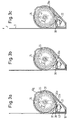
- FIGS. 3a to 3c The function of the belt-sensitive trigger mechanism is illustrated in FIGS. 3a to 3c.
- 3a shows the idle state: in this state, the clutch pawl 34 is held by a compression spring against a stop pin and out of engagement with the internal toothing of the clutch wheel 36.
- the clutch pawl 34 is pivoted on the side of the control disk 32, as a result of which it engages with the internal toothing of the clutch wheel 36 and the clutch wheel 36 is now carried along by the rotation of the belt reel 18.
- the pin 40 engaging in its elongated hole 36d is pressed up at the same time as the control pawl 38, so that it comes into engagement with the locking toothing 28a.
- the pawls 22, 24 are now pivoted in the same manner as previously described for the vehicle-sensitive triggering and brought into engagement with the locking teeth 26a, 28a.
Landscapes
- Engineering & Computer Science (AREA)
- Mechanical Engineering (AREA)
- Automotive Seat Belt Assembly (AREA)
- Handcart (AREA)
Applications Claiming Priority (2)
| Application Number | Priority Date | Filing Date | Title |
|---|---|---|---|
| DE4333760A DE4333760A1 (de) | 1993-10-04 | 1993-10-04 | Gurtaufroller für Rückhaltesysteme in Fahrzeugen |
| DE4333760 | 1993-10-04 |
Publications (3)
| Publication Number | Publication Date |
|---|---|
| EP0646504A2 true EP0646504A2 (fr) | 1995-04-05 |
| EP0646504A3 EP0646504A3 (fr) | 1996-01-17 |
| EP0646504B1 EP0646504B1 (fr) | 1999-02-03 |
Family
ID=6499348
Family Applications (1)
| Application Number | Title | Priority Date | Filing Date |
|---|---|---|---|
| EP94115252A Expired - Lifetime EP0646504B1 (fr) | 1993-10-04 | 1994-09-28 | Enrouleur de ceinture pour des systèmes de retenue dans des véhicules |
Country Status (6)
| Country | Link |
|---|---|
| US (1) | US5524833A (fr) |
| EP (1) | EP0646504B1 (fr) |
| JP (1) | JP2634380B2 (fr) |
| KR (1) | KR0164624B1 (fr) |
| DE (2) | DE4333760A1 (fr) |
| ES (1) | ES2074411T3 (fr) |
Families Citing this family (10)
| Publication number | Priority date | Publication date | Assignee | Title |
|---|---|---|---|---|
| DE19705881C1 (de) * | 1997-02-15 | 1998-07-30 | Autoliv Dev | Gehäuse für eine Sicherheitsgurteinrichtung |
| US5899298A (en) * | 1997-03-19 | 1999-05-04 | Crouse, Jr.; Benjamin F. | Safety harness for stairs |
| GB2354207B (en) | 1999-09-17 | 2001-12-12 | Breed Automotive Tech | Retractor |
| US7862582B2 (en) * | 2006-05-02 | 2011-01-04 | Ethicon Endo-Surgery, Inc. | Suture management |
| EP2242543B1 (fr) * | 2008-01-29 | 2017-07-26 | Carleton Life Support Systems Inc. | Dispositif de verrouillage d'enrouleur pour un dispositif de retenue de passager ayant des positions de verrouillage double |
| EP2247343B1 (fr) * | 2008-02-25 | 2017-12-27 | Honeywell Safety Products USA, Inc. | Systèmes de corde de sécurité à rétractation automatique et systèmes de freinage associés |
| US8516979B2 (en) * | 2010-09-27 | 2013-08-27 | Joseph Ek | Retractable leash with automatic braking mechanism |
| USD929074S1 (en) * | 2018-04-05 | 2021-08-31 | Braunability Uk Limited | Safety belt |
| DE102021105013A1 (de) * | 2021-03-02 | 2022-09-08 | Autoliv Development Ab | Lasttragender Gurtaufroller |
| CN116692245B (zh) * | 2023-07-18 | 2025-12-26 | 泰州润杰物流安全装备科技有限公司 | 一种惯性离心力控制安全收带拉紧装置 |
Family Cites Families (8)
| Publication number | Priority date | Publication date | Assignee | Title |
|---|---|---|---|---|
| US3074761A (en) * | 1961-07-10 | 1963-01-22 | Univ Minnesota | Safety seat belt |
| BE638603A (fr) * | 1962-10-15 | 1964-02-03 | ||
| SE334301B (fr) * | 1965-09-16 | 1971-04-19 | H Karlsson | |
| US3471100A (en) * | 1966-05-17 | 1969-10-07 | Robert N Arcari | Self-adjusting safety reel |
| US3787002A (en) * | 1970-10-20 | 1974-01-22 | Tokai Rika Co Ltd | Emergency locking device for safety seat belt used in motor vehicles and the like |
| JPS5027048Y1 (fr) * | 1970-11-24 | 1975-08-12 | ||
| US4164337A (en) * | 1978-03-16 | 1979-08-14 | General Motors Corporation | Seat belt retractor with pivoted locking mechanism |
| DE3244204A1 (de) * | 1982-11-30 | 1984-05-30 | Hans-Hellmut Dipl.-Ing. 2061 Sülfeld Ernst | Gehaeuse fuer sicherheitsgurtaufrollautomat |
-
1993
- 1993-10-04 DE DE4333760A patent/DE4333760A1/de not_active Withdrawn
-
1994
- 1994-09-28 DE DE59407766T patent/DE59407766D1/de not_active Expired - Fee Related
- 1994-09-28 ES ES94115252T patent/ES2074411T3/es not_active Expired - Lifetime
- 1994-09-28 EP EP94115252A patent/EP0646504B1/fr not_active Expired - Lifetime
- 1994-09-30 KR KR1019940024911A patent/KR0164624B1/ko not_active Expired - Fee Related
- 1994-09-30 US US08/315,588 patent/US5524833A/en not_active Expired - Fee Related
- 1994-10-03 JP JP6238704A patent/JP2634380B2/ja not_active Expired - Lifetime
Also Published As
| Publication number | Publication date |
|---|---|
| ES2074411T3 (es) | 1999-08-01 |
| JPH07149205A (ja) | 1995-06-13 |
| EP0646504A3 (fr) | 1996-01-17 |
| DE59407766D1 (de) | 1999-03-18 |
| JP2634380B2 (ja) | 1997-07-23 |
| KR950011235A (ko) | 1995-05-15 |
| KR0164624B1 (ko) | 1999-02-01 |
| US5524833A (en) | 1996-06-11 |
| ES2074411T1 (es) | 1995-09-16 |
| DE4333760A1 (de) | 1995-04-06 |
| EP0646504B1 (fr) | 1999-02-03 |
Similar Documents
| Publication | Publication Date | Title |
|---|---|---|
| EP0773147B1 (fr) | Rétracteur de ceinture de sécurité pour véhicule | |
| EP0798178B1 (fr) | Rétracteur de sangle | |
| EP0796774A1 (fr) | Rétracteur de ceinture de sécurité comportant un prétentionneur venant en prise avec la bobine d'enroulement | |
| WO1997033778A1 (fr) | Systeme combine pour enrouler et tendre une ceinture, muni d'un limiteur de force | |
| DE3407378A1 (de) | Sicherheitsgurtaufroller mit strammvorrichtung | |
| DE2524874B2 (de) | Vorrichtung zum absorbieren von energie bei kraftfahrzeug-sitzgurten | |
| DE10213906A1 (de) | Leistungsstraffer | |
| DE19820641B4 (de) | Gurtaufwickeleinrichtung | |
| DE2832160A1 (de) | Sicherheitsgurtaufroller | |
| EP0752350B1 (fr) | Rétracteur de sangle pour une ceinture de sécurité | |
| DE3124188C2 (de) | Gurtband-Klemmvorrichtung für Sicherheitsgurte in Kraftfahrzeugen | |
| EP0646504B1 (fr) | Enrouleur de ceinture pour des systèmes de retenue dans des véhicules | |
| DE29500807U1 (de) | Kupplung zwischen der Gurtwelle eines Gurtaufrollers und einem Gurtstraffer-Drehantrieb | |
| EP0717687B1 (fr) | Enrouleur de ceinture de securite | |
| EP0472529B1 (fr) | Enrouleur de ceinture de securite avec dispositif de deblocage | |
| DE4132876A1 (de) | Selbstsperrender gurtaufroller mit retractor-umschaltung | |
| EP2673173B1 (fr) | Rétracteur de ceinture de sécurité pour véhicule | |
| EP0627344B1 (fr) | Enrouleur de ceinture pour systèmes de retenue par ceinture de sécurité dans les véhicules | |
| EP0473832A1 (fr) | Rétracteur de sangle comportant un dispositif de blocage sensible au véhicule à la sangle | |
| DE19544918A1 (de) | Sicherheitsgurtaufroller | |
| EP0543044B1 (fr) | Rétracteur de sangle avec soulagement de traction pour systèmes de retenue par ceinture de sécurité pour véhicules | |
| DE3873878T2 (de) | Gurtband-aufroller. | |
| DE60014118T2 (de) | Sicherheitsgurtaufroller mit sekundärem verriegelungsmechanismus | |
| DE2540671A1 (de) | Aufwickelvorrichtung fuer sicherheitsgurte | |
| EP0261453B1 (fr) | Dispositif pour ajuster la longueur de la sangle d'un système de ceinture |
Legal Events
| Date | Code | Title | Description |
|---|---|---|---|
| PUAI | Public reference made under article 153(3) epc to a published international application that has entered the european phase |
Free format text: ORIGINAL CODE: 0009012 |
|
| AK | Designated contracting states |
Kind code of ref document: A2 Designated state(s): DE ES FR GB IT SE |
|
| ITCL | It: translation for ep claims filed |
Representative=s name: DR. ING. A. RACHELI & C. |
|
| EL | Fr: translation of claims filed | ||
| GBC | Gb: translation of claims filed (gb section 78(7)/1977) | ||
| REG | Reference to a national code |
Ref country code: ES Ref legal event code: BA2A Ref document number: 2074411 Country of ref document: ES Kind code of ref document: T1 |
|
| PUAL | Search report despatched |
Free format text: ORIGINAL CODE: 0009013 |
|
| AK | Designated contracting states |
Kind code of ref document: A3 Designated state(s): DE ES FR GB IT SE |
|
| RAP1 | Party data changed (applicant data changed or rights of an application transferred) |
Owner name: TRW OCCUPANT RESTRAINT SYSTEMS GMBH |
|
| 17P | Request for examination filed |
Effective date: 19960319 |
|
| 17Q | First examination report despatched |
Effective date: 19961127 |
|
| RAP1 | Party data changed (applicant data changed or rights of an application transferred) |
Owner name: TRW OCCUPANT RESTRAINT SYSTEMS GMBH & CO. KG |
|
| GRAG | Despatch of communication of intention to grant |
Free format text: ORIGINAL CODE: EPIDOS AGRA |
|
| GRAG | Despatch of communication of intention to grant |
Free format text: ORIGINAL CODE: EPIDOS AGRA |
|
| GRAH | Despatch of communication of intention to grant a patent |
Free format text: ORIGINAL CODE: EPIDOS IGRA |
|
| GRAH | Despatch of communication of intention to grant a patent |
Free format text: ORIGINAL CODE: EPIDOS IGRA |
|
| GRAA | (expected) grant |
Free format text: ORIGINAL CODE: 0009210 |
|
| AK | Designated contracting states |
Kind code of ref document: B1 Designated state(s): DE ES FR GB IT SE |
|
| PG25 | Lapsed in a contracting state [announced via postgrant information from national office to epo] |
Ref country code: SE Free format text: THE PATENT HAS BEEN ANNULLED BY A DECISION OF A NATIONAL AUTHORITY Effective date: 19990203 |
|
| ITF | It: translation for a ep patent filed | ||
| REF | Corresponds to: |
Ref document number: 59407766 Country of ref document: DE Date of ref document: 19990318 |
|
| GBT | Gb: translation of ep patent filed (gb section 77(6)(a)/1977) |
Effective date: 19990311 |
|
| ET | Fr: translation filed | ||
| REG | Reference to a national code |
Ref country code: ES Ref legal event code: FG2A Ref document number: 2074411 Country of ref document: ES Kind code of ref document: T3 |
|
| PLBE | No opposition filed within time limit |
Free format text: ORIGINAL CODE: 0009261 |
|
| STAA | Information on the status of an ep patent application or granted ep patent |
Free format text: STATUS: NO OPPOSITION FILED WITHIN TIME LIMIT |
|
| 26N | No opposition filed | ||
| PGFP | Annual fee paid to national office [announced via postgrant information from national office to epo] |
Ref country code: GB Payment date: 20000807 Year of fee payment: 7 |
|
| PGFP | Annual fee paid to national office [announced via postgrant information from national office to epo] |
Ref country code: FR Payment date: 20000905 Year of fee payment: 7 |
|
| PGFP | Annual fee paid to national office [announced via postgrant information from national office to epo] |
Ref country code: ES Payment date: 20000926 Year of fee payment: 7 |
|
| PGFP | Annual fee paid to national office [announced via postgrant information from national office to epo] |
Ref country code: DE Payment date: 20000928 Year of fee payment: 7 |
|
| PG25 | Lapsed in a contracting state [announced via postgrant information from national office to epo] |
Ref country code: GB Free format text: LAPSE BECAUSE OF NON-PAYMENT OF DUE FEES Effective date: 20010928 |
|
| PG25 | Lapsed in a contracting state [announced via postgrant information from national office to epo] |
Ref country code: ES Free format text: LAPSE BECAUSE OF NON-PAYMENT OF DUE FEES Effective date: 20010929 |
|
| REG | Reference to a national code |
Ref country code: GB Ref legal event code: IF02 |
|
| PG25 | Lapsed in a contracting state [announced via postgrant information from national office to epo] |
Ref country code: DE Free format text: LAPSE BECAUSE OF NON-PAYMENT OF DUE FEES Effective date: 20020501 |
|
| GBPC | Gb: european patent ceased through non-payment of renewal fee |
Effective date: 20010928 |
|
| PG25 | Lapsed in a contracting state [announced via postgrant information from national office to epo] |
Ref country code: FR Free format text: LAPSE BECAUSE OF NON-PAYMENT OF DUE FEES Effective date: 20020531 |
|
| REG | Reference to a national code |
Ref country code: FR Ref legal event code: ST |
|
| REG | Reference to a national code |
Ref country code: ES Ref legal event code: FD2A Effective date: 20021011 |
|
| PG25 | Lapsed in a contracting state [announced via postgrant information from national office to epo] |
Ref country code: IT Free format text: LAPSE BECAUSE OF NON-PAYMENT OF DUE FEES Effective date: 20050928 |