EP0646676A2 - Dispositif d'entretien avec support réglable en hauteur pour une brosse cylindrique - Google Patents
Dispositif d'entretien avec support réglable en hauteur pour une brosse cylindrique Download PDFInfo
- Publication number
- EP0646676A2 EP0646676A2 EP94113707A EP94113707A EP0646676A2 EP 0646676 A2 EP0646676 A2 EP 0646676A2 EP 94113707 A EP94113707 A EP 94113707A EP 94113707 A EP94113707 A EP 94113707A EP 0646676 A2 EP0646676 A2 EP 0646676A2
- Authority
- EP
- European Patent Office
- Prior art keywords
- maintenance
- chassis
- maintenance tool
- care device
- roller
- Prior art date
- Legal status (The legal status is an assumption and is not a legal conclusion. Google has not performed a legal analysis and makes no representation as to the accuracy of the status listed.)
- Granted
Links
Images




Classifications
-
- E—FIXED CONSTRUCTIONS
- E01—CONSTRUCTION OF ROADS, RAILWAYS, OR BRIDGES
- E01H—STREET CLEANING; CLEANING OF PERMANENT WAYS; CLEANING BEACHES; DISPERSING OR PREVENTING FOG IN GENERAL CLEANING STREET OR RAILWAY FURNITURE OR TUNNEL WALLS
- E01H1/00—Removing undesirable matter from roads or like surfaces, with or without moistening of the surface
- E01H1/02—Brushing apparatus, e.g. with auxiliary instruments for mechanically loosening dirt
- E01H1/04—Brushing apparatus, e.g. with auxiliary instruments for mechanically loosening dirt taking- up the sweepings, e.g. for collecting, for loading
- E01H1/045—Brushing apparatus, e.g. with auxiliary instruments for mechanically loosening dirt taking- up the sweepings, e.g. for collecting, for loading the loading means being a rotating brush with horizontal axis
-
- A—HUMAN NECESSITIES
- A01—AGRICULTURE; FORESTRY; ANIMAL HUSBANDRY; HUNTING; TRAPPING; FISHING
- A01B—SOIL WORKING IN AGRICULTURE OR FORESTRY; PARTS, DETAILS, OR ACCESSORIES OF AGRICULTURAL MACHINES OR IMPLEMENTS, IN GENERAL
- A01B45/00—Machines for treating meadows or lawns, e.g. for sports grounds
-
- A—HUMAN NECESSITIES
- A01—AGRICULTURE; FORESTRY; ANIMAL HUSBANDRY; HUNTING; TRAPPING; FISHING
- A01G—HORTICULTURE; CULTIVATION OF VEGETABLES, FLOWERS, RICE, FRUIT, VINES, HOPS OR SEAWEED; FORESTRY; WATERING
- A01G20/00—Cultivation of turf, lawn or the like; Apparatus or methods therefor
- A01G20/40—Apparatus for cleaning the lawn or grass surface
- A01G20/43—Apparatus for cleaning the lawn or grass surface for sweeping, collecting or disintegrating lawn debris
Definitions
- the invention relates to a maintenance device for maintaining substantially flat surfaces, preferably in the communal, private or commercial area, such as green areas, paved areas or the like, with a device which can be attached via a drawbar to a tractor vehicle with a PTO shaft, for example a tractor or the like Chassis which has at least one axle with at least two wheels, a receiving device fastened to the chassis for goods received from the area to be maintained, such as, for example, mown plant parts, swept up impurities such as leaves, garbage, sand, grit or the like, and with one arranged on the chassis maintenance unit, which has at least one rotationally driven maintenance tool, such as a flail mower, a sweeping roller and / or a scarifying roller or the like.
- a maintenance device for maintaining substantially flat surfaces, preferably in the communal, private or commercial area, such as green areas, paved areas or the like, with a device which can be attached via a drawbar to a tractor vehicle with a PTO shaft, for example a tractor or
- DE-OS 3713445 discloses a device for the maintenance of green areas consisting of a chassis with wheels attached to a towing vehicle with a PTO shaft with wheels and a receptacle for mowed grass, leaves or the like, a maintenance unit with pendulum wheels suspended in the chassis frame and at least one roller-shaped maintenance tool, which is mounted in side plates of the maintenance unit and is driven on one side by the PTO shaft via a gear train.
- this previously known device provides that a lifting cylinder is arranged between the chassis frame and the maintenance unit, and that the roller-shaped maintenance tool is detachably received in the side plates and can be removed in the released state when the maintenance unit is raised.
- the replacement of the floor-side maintenance tool is carried out with the aid of axially pluggable axle bolts, the axle bolt being designed as a wedge element which engages through the driving V-belt hub and engages in the maintenance tool.
- the V-belt pulley and the maintenance tool are non-rotatably connected.
- This embodiment of the known device has proven particularly effective in that the floor-side maintenance tool can be replaced in a simple and quick manner. In this case, however, it is necessary that the device is raised at least to such an extent that the maintenance tool can be pulled out of the area of the chassis frame to the front or to the side after it has been dismantled. As a result, the lifting dimension of the device is essentially determined by the diameter of the maintenance tool.
- the connecting elements between the maintenance tool and the chassis frame namely the axle bolts designed as wedge elements and the driving V-belt hub or the connection of the axle bolt with the maintenance tool, have a high degree of manufacturing accuracy, so that over a predetermined operating time proper operation of this known device is guaranteed. Otherwise there is the disadvantage that there is play at lower manufacturing accuracies between the above-mentioned components, so that the connection between the chassis frame and the maintenance tool deflects over time. This results in a rattling or fluttering of the pulley, which on the one hand leads to increased noise pollution when working with the previously known device and on the other hand to a high level of maintenance of this device.
- the invention has for its object to provide a generic maintenance device that is structurally simple, good ground adaptation and can be easily adapted to different conditions of use.
- the solution to this problem provides that the maintenance tool is held in a frame or the like, which can be connected to or detached from the chassis such that the structural unit (40) thus formed can be removed from the chassis or independent of other devices. can be inserted.
- the structural unit is held on the chassis in an approximately horizontal direction laterally to the direction of travel and can be removed.
- this procedure ensures that, for the purpose of replacing or changing the care devices to be used and their maintenance, only the assembly from the respective care tool and associated frame are removed from the device or the special care area such as the sweeping head or the like, and used again can without special procedures such as erecting the chassis for spacing the maintenance tool from the floor to be maintained must be provided in case of doubt.
- the maintenance device is based on the idea of not only replacing the maintenance tool, for example the sweeping roller, flail mower or scarifying roller, but also designing a lower part of a sweeping head housing, on which the lower maintenance tool is held, as a modular unit.
- the bearing between the lower maintenance tool and the V-belt pulley can be carried out precisely and rigidly in the usual way, so that there are no deflections of the aforementioned Kind can occur.
- a V-belt pulley is assigned to the respective maintenance tool, which is adapted to the desired number of revolutions.
- the maintenance tools are driven via the PTO shaft drive, which is connected to a bevel gear, which has V-belt pulleys on the output side, one of which is assigned, for example, to an upper sweeping roller and the other of which is assigned to the bottom-side maintenance tool.
- V-belt drives remain unchanged when the maintenance tool is replaced.
- the associated V-belts are simply put on as a function of the desired number of revolutions when the maintenance tool is replaced. This can already be done at the factory. This configuration makes it much easier to replace the maintenance tool, since only the frame of the maintenance device has to be detached from the chassis and pulled out.
- the maintenance tool is stored in this frame together with the V-belt pulley.
- This frame can then be exchanged for another frame, for example one Flail mower or a scarifying roller.
- another frame for example one Flail mower or a scarifying roller.
- An upstream countershaft transmission which adjusts the corresponding speeds, can therefore be dispensed with.
- the care unit has a transport roller in addition to the care tool, which is preferably designed as a rotatingly driven brush and is arranged between the care tool and the receiving device.
- This transport roller is preferably also part of the frame, so that when the maintenance unit is replaced, both the maintenance tool and the transport roller can be removed from the chassis together with the frame. Maintenance tool and transport roller thus form a single unit.
- a maintenance device it is further provided in a maintenance device according to the invention that the maintenance tool and the transport roller are driven by a drive device which can be driven by the towing vehicle via the PTO shaft.
- a drive device which can be driven by the towing vehicle via the PTO shaft.
- This is the bevel gear already mentioned above, which carries V-belt pulleys on the output side, with the transport roller being driven via at least one V-belt pulley and the maintenance tool being driven via at least one further V-belt pulley.
- both the maintenance tool, the transport roller and the drive device have pulleys which are connected to one another via at least one drive belt, the speed of the maintenance tool and the transport roller being in relation to the belt pulley of the drive device appropriately dimensioned pulleys is adjustable.
- the drive device is preferably firmly connected to the chassis.
- the storage of the care unit is slidable in the frame, so that the spatial Assignment of the maintenance unit to the transport roller can be changed to one another.
- This feature is particularly advantageous for sweeping rollers as a floor-side maintenance tool, since these sweeping rollers should be at a certain distance from a baffle plate in order to ensure that the swept material taken up is conveyed to the further transport roller. This is necessary, for example, in adaptation to the bristle wear. For manufacturing reasons, such adjustability is also desirable for other maintenance tools in order to be able to optimize the gap width accordingly even with flail mowers.
- the frame and the maintenance unit and / or the transport roller form a sweeping head which is pivotally mounted about a pivot point, it having proven to be advantageous if the pivot point in the working direction of the device behind the wheels lies.
- the sweeping head is a separately pivotable element which, in connection with front support wheels, ensures the alignment of the sweeping roller to the floor, with height adjustability being able to provide signs of wear and tear of the maintenance tool or an exact adjustment of cutting tools of the maintenance tool.
- chassis has longitudinal beams which are preferably U-shaped in cross-section such that they allow limited torsion.
- the carriers of the chassis of a device or the sweeping head of a previously known device towards the rear pivot point have been designed as tubular profiles which are relatively rigid.
- the now proposed innovation in that longitudinal members are used that allow a limited torsion has the advantage that an inclined position of the front support wheels and thus the roller relative to the rear wheels is made possible, which leads to better ground adaptation, especially when using mowing rollers in non-planar areas Terrain leads.
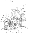
- a care device 1 shown in the figures consists of a chassis 2 which has at least two longitudinal beams 3 arranged in parallel in the direction of travel, which are connected to one another via an axis arranged at right angles to the longitudinal beams 3.
- Impellers 4, which stand on the surface 5 to be machined, are rotatably arranged on both sides of the axis.
- the direction of travel of the care device 1 pulled by a towing vehicle, not shown, is shown in FIG. 1 by an arrow 6, the direction of travel in the working position of the care device 1 being indicated thereby.
- the care device 1 is connected to the towing vehicle, not shown, via a tiller, not shown, which is pivotally articulated in the horizontal direction at the front end, which lies opposite the running wheels 4.
- a connection between the towing vehicle, not shown, and the maintenance device 1 via a shaft, not shown, which is arranged on the one hand on a PTO shaft of the towing vehicle and on the other hand on a PTO shaft connection 7 of the maintenance device 1 in such a way that the torque output by the PTO shaft is transmitted to the PTO shaft connection 7 the care device 1 is transferred.
- the PTO shaft connection 7 is connected to a bevel gear 8, which is arranged in the front area of the chassis 2 and has at least two pulleys 9 on the output side.
- the care device 1 has in its front area facing the towing vehicle at least one support wheel 10 which is fixedly connected to the chassis 2 via a height adjustment device 11.
- the support wheel 10 is in this case rotatably arranged in the height adjustment device 11 so that it can follow cornering of the maintenance device 1.
- the care device 1 has a receiving device 12, which is designed as a container and has in its rear region a tilting opening, not shown, which is closed by a lid, which is also not shown and is pivotably articulated.
- the receiving device 12 is preferably tiltable about a pivot point in the rear region of the chassis, so that the material conveyed into the receiving device 12, namely, for example, mown plant parts, swept up impurities such as leaves, garbage, sand, grit or the like via the rear one with the lid closed opening can be removed from the receiving device 12.
- the receiving device 12 is pivoted about its rear pivot point by means of a linear motor, for example a hydraulic cylinder, whereby the cover of the receiving device 12 is also pivoted about its pivot point and opens the opening in the rear part of the receiving device 12.
- the care device 1 has a sweeping head 13, which consists of a frame 14 and a care unit 15 inserted into the frame 14.
- the maintenance unit 15 has a maintenance tool 16 in the form of a sweeping roller 17 (see FIG. 3), a scarifying roller 18 (see FIG. 4) or a flail mower 19 (see FIG. 5), the maintenance tool 16 having an axis 20 in its center has, at one end, at least one pulley 21 is arranged in a rotationally fixed manner, which is operatively connected to the pulley 2 of the bevel gear 8 via at least one drive belt 22.
- the care unit 15 has a transport roller 23 which is arranged above the care tool 16 in a conveying channel 24 directly in front of an inlet opening 25 of the receiving device 12.
- the transport roller 23 also has an axis of rotation 26 arranged in its center, which is provided at one end with at least one non-rotatably arranged pulley 27, which is connected to the pulley 9 of the bevel gear 8 via a drive belt 28.
- both the maintenance tool 16 and the transport roller 23 are driven in rotation in the same direction via the PTO shaft of the towing vehicle, not shown.
- the transmission of the torque of the PTO shaft and the setting of the required speed of the maintenance tool 16 and the transport roller 23 takes place here via the bevel gear 8, the pulley 9, the drive belts 22 and 28 and the pulleys 21 and 27.
- the sweeping head 3 is shown in detail in FIG. 2, so that the gear connection between the PTO shaft connection 7 and the maintenance tool 16 or the transport roller 23 is clearly recognizable.
- the maintenance device 1 can be equipped with various sweeping heads 13, so that, for example, the maintenance tools 16 shown in FIGS. 3 to 5, namely the sweeping roller 17, the scarifying roller 18 or the flail mower 19, can be inserted into the chassis 2 of the maintenance device 1.
- a pulley 21 with a larger diameter is consequently used than in the scarifying roller 18 or in the flail mower 19, since the sweeping roller 17 rotates at only 800 rpm, whereas the scarifying roller 18 and the flail mower 19 each have a number of revolutions of about 2000 min ⁇ 1 to ensure satisfactory or optimal operation. Accordingly, it is only necessary in the care device 1 according to the invention to adapt the drive belt 22 to the corresponding pulley 21 of the care tool 16.
- the drive belt 28 for driving the transport roller 23 can essentially remain unchanged in all of the above-mentioned maintenance tools 16, since the number of revolutions of the transport roller 23 is essentially independent of the number of revolutions of the maintenance device 16 with regard to the optimal functioning of this maintenance tool 16.
- the sweeping head 13 can be pivoted about a pivot point behind the impellers 4. This pivoting movement is effected by a cylinder 29.
- a spindle drive can also be provided, which enables a purely mechanical pivoting movement of the sweeping head 13.
- the sweeping head 13 is a separately pivotable element.
- the height adjustment of the sweeping head 13 is also carried out by means of the front support wheel 10, which is connected to the chassis 2 in a height-adjustable manner via the height adjustment device 11.
- the alignment of the maintenance tool 16 with respect to the surface 5 to be machined is set, on the one hand, for example to show signs of wear to compensate for the sweeping roller 17 or, on the other hand, to ensure an exact setting of the cutting tools of the flail mower 19 or the scarifying roller 18.
- the receiving device 12 is provided on the side with a V-shaped cutout which extends over the axis 20 of the maintenance tool 16.
- This configuration allows, for example, the maintenance tool 16 to be removed laterally without the chassis 2 having to be raised unnecessarily high.
- the receiving device 12 is sealed against backflow of small goods.
- the receptacle 12 in the region of its inlet opening 25 obliquely downwards and obliquely upwards to the respective receptacle surface facing diaphragms 30 and 31, which are connected to guide plates 32 and 33 projecting into the conveying channel 24 and form an L-shaped profile in cross section .
- diaphragms 30 and 31 above and below the inlet opening 25 diaphragms, not shown, are also arranged laterally in the inlet opening 25 and seal the receiving device 12 against small material flowing back.
- the receiving device 12 is designed somewhat wider than the sweeping head 13 or the inlet opening 25 to the inside of the receiving device 12.
- FIGS. 3 to 5 show various sweeping heads 13, the sweeping head 13 shown in FIG. 3 having the sweeping roller 17, which is arranged below the transport roller 23 in the conveying channel 24.
- the conveying channel 24 is formed, among other things, by a front wall 34, which at its end facing the surface 5 to be machined has a step 35 which extends forwards, ie in the direction of arrow 6 (cf. FIG. 1), to which a baffle flap directed downward 36 is attached.
- This impact flap 36 must of course yield to the not yet mowed grass, or the impurities arranged on the surface 5 to be worked, so that it can be pivoted and is therefore insofar as far from the maintenance tool 16, ie in FIG. 3 from the sweeping roller 17, in FIG in Figure 5 arranged from the flail mower 19. In the case of the flail mower 19, as shown in FIG. 5, it is thus achieved that the impact flap 36 does not get into the circumferential area of the knives 37 of the flail mower 19.
- FIGS. 3 and 5 an alternative arrangement of a baffle flap 38 is also shown in dashed lines, which is arranged closer to the circumference of the maintenance tool 16, but tangentially to the bumping tool, in comparison to the baffle flaps 36.
- This recessed impact flap 38 can be arranged either alternatively or in addition to the impact flap 36 and consequently projects forward in the direction of arrow 6, which indicates the direction of travel of the care device 1 in the working position.
- the sweeping roller 17 rotating in the direction of arrow 39 generates a sufficiently large suction due to its rotating movement to convey the absorbed material to the transport roller 23 even with this arrangement of the impact flap 38.
- FIG. 4 which shows a sweeping head 13 with a scarifying roller 18, it can also be seen that in the area of the gradation 35 a counter knife 40 running in the horizontal direction is provided as an additional device, that for further comminution of the mowed by the scarifying roller 18 and thrown up good.
- the storage of the care unit 15 in the frame 14 is slidable, so that the spatial assignment of the care tool 16 to the transport roller 23 can be changed.
- This embodiment is particularly advantageous when using a sweeping roller 17 as a maintenance tool 16, since the sweeping roller 17 should have a certain distance from the impact flap 36 in order to ensure the conveyed goods are conveyed to the further transport roller 23. This is necessary, for example, in adaptation to the bristle wear.
- adjustability is also desirable in order to be able to optimize the gap width between the knives 37 of the flail mower 19 to the impact flap 38.
- the longitudinal beams 3 are U-shaped in cross-section in order to allow a limited torsion of the longitudinal beams 3, so that an inclined position of the front support wheels 10 and thus of the maintenance tool 16 is made possible.
- a better ground adaptation of the maintenance tool 16 is achieved, in particular when using a sweeping roller 17 in non-even terrain.
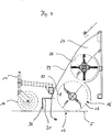
- FIG. 6 shows an enlarged section of the side views, in particular of the examples in FIGS. 1 and 2, with a support which is arranged in the vicinity of the maintenance tool 16, namely in the longitudinal direction of the mobile device, on the side of the maintenance tool facing away from the support wheels 10.
- This support consists of a roller 41 which is symbolized by means of a height adjustment device 42 - symbolically adjustable in the exemplary embodiment from the chassis 2 or its longitudinal members 3.
- Such a support is advisable when it comes down to a precise spacing of the maintenance tool or its circumference from the ground to be worked, as is the case in particular when the maintenance tool is designed as a flail mower.
- the support roller 41 In order not to impair this spacing by excessive contamination of the lateral surface of the support roller 41, it is designed to be self-cleaning, i.e. a stripping device, not shown, acts on its outer surface, which removes dirt adhering to the outer surface.
- FIG. 7 shows a rear view of the maintenance tool arrangement on the bottom provided with the support in a schematic representation, from which the support roller 41, which is adjustable by means of the height adjustment 42, can be seen as extending over the majority of the Width of the care device is visible extending.
- the sweeping tool 16 is indicated with respect to its axis driven via the pulley 21 and outlined schematically with regard to its working surface.
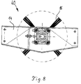
- FIG. 8 is intended to make it very clear what can be removed as a unit 40 from all the other devices from the care device or inserted into it, specifically with a carrier 14 in which differently designed care devices 16 can be used.
- the different maintenance tools 16 are preferably provided prepared with their carriers. This avoids work associated with the pivoting of the care devices. It is only necessary to insert the respective assembly, namely carrier plus sweeping roller, carrier plus flail mower, carrier plus scarifying roller, etc., into the maintenance device, as shown in the exemplary embodiments, in a so-called sweeper head which has a transport roller arranged above the maintenance tool , which picks up the sweepings, the mowing material or the residues resulting from scarifying and transfers them into the receiving device provided for this purpose. This transport roller along with the sweeping head and the like always remains in place when a unit consisting of maintenance tool and carrier is replaced.
Landscapes
- Life Sciences & Earth Sciences (AREA)
- Engineering & Computer Science (AREA)
- Environmental Sciences (AREA)
- Architecture (AREA)
- Civil Engineering (AREA)
- Structural Engineering (AREA)
- Soil Sciences (AREA)
- Mechanical Engineering (AREA)
- Harvester Elements (AREA)
- Road Repair (AREA)
- Road Paving Machines (AREA)
- Coating Apparatus (AREA)
- Brushes (AREA)
- Cleaning In General (AREA)
Applications Claiming Priority (2)
| Application Number | Priority Date | Filing Date | Title |
|---|---|---|---|
| DE9313169U | 1993-09-01 | ||
| DE9313169 | 1993-09-01 |
Publications (3)
| Publication Number | Publication Date |
|---|---|
| EP0646676A2 true EP0646676A2 (fr) | 1995-04-05 |
| EP0646676A3 EP0646676A3 (fr) | 1995-08-02 |
| EP0646676B1 EP0646676B1 (fr) | 1999-12-15 |
Family
ID=6897544
Family Applications (1)
| Application Number | Title | Priority Date | Filing Date |
|---|---|---|---|
| EP94113707A Expired - Lifetime EP0646676B1 (fr) | 1993-09-01 | 1994-09-01 | Dispositif d'entretien avec support réglable en hauteur pour une brosse cylindrique |
Country Status (3)
| Country | Link |
|---|---|
| EP (1) | EP0646676B1 (fr) |
| AT (1) | ATE187786T1 (fr) |
| DE (2) | DE4431182A1 (fr) |
Cited By (3)
| Publication number | Priority date | Publication date | Assignee | Title |
|---|---|---|---|---|
| AU682883B2 (en) * | 1993-07-20 | 1997-10-23 | Rodney Mackenzie Pettigrew | Surface treatment apparatus including brush means and impact means mounted on a single shaft |
| AU726437B2 (en) * | 1997-01-30 | 2000-11-09 | Peter Harry Whitton | Turf renovation sweeper and grader |
| JP2020090875A (ja) * | 2018-12-07 | 2020-06-11 | 有限会社河島農具製作所 | 芝生清掃車のブラシ高さ調整構造 |
Families Citing this family (3)
| Publication number | Priority date | Publication date | Assignee | Title |
|---|---|---|---|---|
| DE10325187B4 (de) * | 2002-06-04 | 2007-10-18 | Keusch, Siegfried, Dipl.-Ing. | Spindelmäher |
| WO2007011398A2 (fr) * | 2004-10-21 | 2007-01-25 | Deka Products Limited Partnership | Dispositif de lancement commande |
| CN103015351A (zh) * | 2011-09-22 | 2013-04-03 | 陈德伦 | 新型轻便扫地车 |
Family Cites Families (8)
| Publication number | Priority date | Publication date | Assignee | Title |
|---|---|---|---|---|
| DE1759781A1 (de) * | 1968-06-07 | 1971-07-29 | Rasma Ag | Kehrmaschine,insbesondere Rasenkehrmaschine |
| US3879786A (en) * | 1974-02-07 | 1975-04-29 | Ecolotec Inc | Pivotable rotary brush drive assembly |
| DE2460584C3 (de) * | 1974-12-20 | 1980-01-31 | Wiedenmann Gmbh, 7901 Rammingen | Kehrmaschine |
| DE3034741C2 (de) * | 1980-09-15 | 1983-05-11 | Ing. Alfred Schmidt Gmbh, 7822 St Blasien | Kehrmaschine mit einer an einem Trägerfahrzeug lösbar angeordneten Kehrgruppe |
| DE3512730A1 (de) * | 1985-04-09 | 1986-10-09 | "Saku" Maschinenbau A. Schmid, 8398 Pocking | Strassenkehrmaschine |
| DE3641634A1 (de) * | 1986-12-05 | 1988-06-16 | Eggenmueller Alfred | Sammelmaschine, insbesondere kehrmaschine, mit auswechselbaren werkzeugen |
| DE3713445A1 (de) * | 1987-04-22 | 1988-11-03 | Wiedenmann Gmbh | Vorrichtung zur pflege von gruenflaechen |
| DE4001088C2 (de) * | 1990-01-17 | 1998-09-17 | Smv | Kehrfahrzeug |
-
1994
- 1994-09-01 EP EP94113707A patent/EP0646676B1/fr not_active Expired - Lifetime
- 1994-09-01 AT AT94113707T patent/ATE187786T1/de not_active IP Right Cessation
- 1994-09-01 DE DE4431182A patent/DE4431182A1/de not_active Ceased
- 1994-09-01 DE DE59409003T patent/DE59409003D1/de not_active Expired - Fee Related
Cited By (3)
| Publication number | Priority date | Publication date | Assignee | Title |
|---|---|---|---|---|
| AU682883B2 (en) * | 1993-07-20 | 1997-10-23 | Rodney Mackenzie Pettigrew | Surface treatment apparatus including brush means and impact means mounted on a single shaft |
| AU726437B2 (en) * | 1997-01-30 | 2000-11-09 | Peter Harry Whitton | Turf renovation sweeper and grader |
| JP2020090875A (ja) * | 2018-12-07 | 2020-06-11 | 有限会社河島農具製作所 | 芝生清掃車のブラシ高さ調整構造 |
Also Published As
| Publication number | Publication date |
|---|---|
| EP0646676B1 (fr) | 1999-12-15 |
| DE4431182A1 (de) | 1995-04-27 |
| EP0646676A3 (fr) | 1995-08-02 |
| DE59409003D1 (de) | 2000-01-20 |
| ATE187786T1 (de) | 2000-01-15 |
Similar Documents
| Publication | Publication Date | Title |
|---|---|---|
| DE2461748C2 (de) | Mähvorrichtung | |
| DE2814440A1 (de) | Erntemaschine | |
| DE202006016981U1 (de) | Kombinationsgerät zum Schneefräsen, Mähen, Vertikutieren oder Bodenhacken | |
| DE102012101109B4 (de) | Geräteträger für Reinigungsgeräte mit Mittenantrieb zum Frontanbau | |
| DE102005026754A1 (de) | Fahrzeug | |
| DE2818314A1 (de) | Geblaeseeinrichtung fuer das entfernen von laub, maehgut o.dgl. | |
| DE29719508U1 (de) | Anbau-Kehrvorrichtung mit Aufnahmeeinrichtung | |
| EP0646676B1 (fr) | Dispositif d'entretien avec support réglable en hauteur pour une brosse cylindrique | |
| DE102011075472B4 (de) | Erdkegelbearbeitungsvorrichtung | |
| DE3603902A1 (de) | Motorgetriebener rasenmaeher | |
| WO2017009098A1 (fr) | Machine de nettoyage du sol et procédé pour faire fonctionner une machine de nettoyage du sol | |
| EP0518167B1 (fr) | Véhicule | |
| DE69512559T2 (de) | Heuwerbungsmaschine, insbesondere ein Schwader für Futter | |
| EP0025848B1 (fr) | Véhicule automoteur muni d'instruments de travail, en particulier véhicule agricole | |
| DE9420899U1 (de) | Kehrgerät | |
| EP0470560B1 (fr) | Véhicule de traitement de sol | |
| DE69418738T2 (de) | Untersetzungsgetriebe für selbstangetriebene Rasenmäher | |
| DE3118493A1 (de) | "saugkehrvorrichtung" | |
| EP0368021B1 (fr) | Balai-ramasseur à gazon | |
| DE8623442U1 (de) | Gerät für das Kehren von Flächen | |
| DE3013544A1 (de) | Graslader zum anbau an maehgeraete | |
| DE3713445C2 (fr) | ||
| DE10325033B3 (de) | Antriebseinheit für eine Materialfördereinrichtung, insbesondere für ein Grasaufnahmefahrzeug | |
| EP0368019B1 (fr) | Appareil à tondre et aérer le gazon | |
| DE19620070A1 (de) | Arbeitsaggregatekombination an einem selbstfahrenden Trägerfahrzeug |
Legal Events
| Date | Code | Title | Description |
|---|---|---|---|
| PUAI | Public reference made under article 153(3) epc to a published international application that has entered the european phase |
Free format text: ORIGINAL CODE: 0009012 |
|
| AK | Designated contracting states |
Kind code of ref document: A2 Designated state(s): AT CH DE LI |
|
| PUAL | Search report despatched |
Free format text: ORIGINAL CODE: 0009013 |
|
| AK | Designated contracting states |
Kind code of ref document: A3 Designated state(s): AT CH DE LI NL PT SE |
|
| 17P | Request for examination filed |
Effective date: 19951130 |
|
| RBV | Designated contracting states (corrected) |
Designated state(s): AT CH DE LI |
|
| 17Q | First examination report despatched |
Effective date: 19980720 |
|
| GRAG | Despatch of communication of intention to grant |
Free format text: ORIGINAL CODE: EPIDOS AGRA |
|
| GRAG | Despatch of communication of intention to grant |
Free format text: ORIGINAL CODE: EPIDOS AGRA |
|
| GRAH | Despatch of communication of intention to grant a patent |
Free format text: ORIGINAL CODE: EPIDOS IGRA |
|
| GRAH | Despatch of communication of intention to grant a patent |
Free format text: ORIGINAL CODE: EPIDOS IGRA |
|
| GRAA | (expected) grant |
Free format text: ORIGINAL CODE: 0009210 |
|
| AK | Designated contracting states |
Kind code of ref document: B1 Designated state(s): AT CH DE LI |
|
| REF | Corresponds to: |
Ref document number: 187786 Country of ref document: AT Date of ref document: 20000115 Kind code of ref document: T |
|
| REG | Reference to a national code |
Ref country code: CH Ref legal event code: EP |
|
| REG | Reference to a national code |
Ref country code: CH Ref legal event code: NV Representative=s name: PATENTANWALTSBUERO EDER AG |
|
| REF | Corresponds to: |
Ref document number: 59409003 Country of ref document: DE Date of ref document: 20000120 |
|
| PG25 | Lapsed in a contracting state [announced via postgrant information from national office to epo] |
Ref country code: AT Free format text: LAPSE BECAUSE OF NON-PAYMENT OF DUE FEES Effective date: 20000901 |
|
| PG25 | Lapsed in a contracting state [announced via postgrant information from national office to epo] |
Ref country code: LI Free format text: LAPSE BECAUSE OF NON-PAYMENT OF DUE FEES Effective date: 20000930 Ref country code: CH Free format text: LAPSE BECAUSE OF NON-PAYMENT OF DUE FEES Effective date: 20000930 |
|
| PLBE | No opposition filed within time limit |
Free format text: ORIGINAL CODE: 0009261 |
|
| STAA | Information on the status of an ep patent application or granted ep patent |
Free format text: STATUS: NO OPPOSITION FILED WITHIN TIME LIMIT |
|
| 26N | No opposition filed | ||
| REG | Reference to a national code |
Ref country code: CH Ref legal event code: PL |
|
| PGFP | Annual fee paid to national office [announced via postgrant information from national office to epo] |
Ref country code: DE Payment date: 20021114 Year of fee payment: 9 |
|
| PG25 | Lapsed in a contracting state [announced via postgrant information from national office to epo] |
Ref country code: DE Free format text: LAPSE BECAUSE OF NON-PAYMENT OF DUE FEES Effective date: 20040401 |