EP0646762A1 - Verbrennbare Hulsenteile für Artilleriegeschosse, Verfahren zu deren Herstellung und Verwendung derselben - Google Patents
Verbrennbare Hulsenteile für Artilleriegeschosse, Verfahren zu deren Herstellung und Verwendung derselben Download PDFInfo
- Publication number
- EP0646762A1 EP0646762A1 EP94402205A EP94402205A EP0646762A1 EP 0646762 A1 EP0646762 A1 EP 0646762A1 EP 94402205 A EP94402205 A EP 94402205A EP 94402205 A EP94402205 A EP 94402205A EP 0646762 A1 EP0646762 A1 EP 0646762A1
- Authority
- EP
- European Patent Office
- Prior art keywords
- central
- elements
- neck
- combustible
- felting
- Prior art date
- Legal status (The legal status is an assumption and is not a legal conclusion. Google has not performed a legal analysis and makes no representation as to the accuracy of the status listed.)
- Granted
Links
- 238000000034 method Methods 0.000 title claims abstract description 14
- 238000004519 manufacturing process Methods 0.000 title claims description 6
- 239000000843 powder Substances 0.000 claims abstract description 37
- 238000009950 felting Methods 0.000 claims abstract description 24
- 230000000295 complement effect Effects 0.000 claims abstract description 20
- 239000003380 propellant Substances 0.000 claims description 22
- 239000000446 fuel Substances 0.000 claims description 19
- 239000000020 Nitrocellulose Substances 0.000 claims description 10
- 229920001220 nitrocellulos Polymers 0.000 claims description 10
- 239000007900 aqueous suspension Substances 0.000 claims description 8
- 239000007788 liquid Substances 0.000 claims description 7
- 239000000835 fiber Substances 0.000 claims description 6
- 229920003043 Cellulose fiber Polymers 0.000 claims description 5
- 239000011347 resin Substances 0.000 claims description 5
- 229920005989 resin Polymers 0.000 claims description 5
- 238000005054 agglomeration Methods 0.000 claims description 4
- 230000002776 aggregation Effects 0.000 claims description 4
- 239000011230 binding agent Substances 0.000 claims description 4
- 229920001004 polyvinyl nitrate Polymers 0.000 claims description 4
- 210000003739 neck Anatomy 0.000 abstract description 46
- 239000000725 suspension Substances 0.000 description 8
- 238000001914 filtration Methods 0.000 description 7
- 238000011049 filling Methods 0.000 description 5
- DMBHHRLKUKUOEG-UHFFFAOYSA-N diphenylamine Chemical compound C=1C=CC=CC=1NC1=CC=CC=C1 DMBHHRLKUKUOEG-UHFFFAOYSA-N 0.000 description 4
- 239000000463 material Substances 0.000 description 4
- 230000005540 biological transmission Effects 0.000 description 3
- 238000002485 combustion reaction Methods 0.000 description 3
- 238000010304 firing Methods 0.000 description 3
- 230000001141 propulsive effect Effects 0.000 description 3
- PXHVJJICTQNCMI-UHFFFAOYSA-N Nickel Chemical compound [Ni] PXHVJJICTQNCMI-UHFFFAOYSA-N 0.000 description 2
- 239000000654 additive Substances 0.000 description 2
- 229920002678 cellulose Polymers 0.000 description 2
- 239000001913 cellulose Substances 0.000 description 2
- 238000010411 cooking Methods 0.000 description 2
- 230000008021 deposition Effects 0.000 description 2
- 239000003292 glue Substances 0.000 description 2
- 238000011068 loading method Methods 0.000 description 2
- 239000007787 solid Substances 0.000 description 2
- 238000003856 thermoforming Methods 0.000 description 2
- 239000004925 Acrylic resin Substances 0.000 description 1
- 229920000178 Acrylic resin Polymers 0.000 description 1
- 208000031968 Cadaver Diseases 0.000 description 1
- RYGMFSIKBFXOCR-UHFFFAOYSA-N Copper Chemical compound [Cu] RYGMFSIKBFXOCR-UHFFFAOYSA-N 0.000 description 1
- 206010061218 Inflammation Diseases 0.000 description 1
- SNIOPGDIGTZGOP-UHFFFAOYSA-N Nitroglycerin Chemical compound [O-][N+](=O)OCC(O[N+]([O-])=O)CO[N+]([O-])=O SNIOPGDIGTZGOP-UHFFFAOYSA-N 0.000 description 1
- 239000000853 adhesive Substances 0.000 description 1
- 230000001070 adhesive effect Effects 0.000 description 1
- 230000003416 augmentation Effects 0.000 description 1
- 230000015572 biosynthetic process Effects 0.000 description 1
- 239000003795 chemical substances by application Substances 0.000 description 1
- 238000000576 coating method Methods 0.000 description 1
- 238000005056 compaction Methods 0.000 description 1
- 239000002131 composite material Substances 0.000 description 1
- 239000000470 constituent Substances 0.000 description 1
- 229910052802 copper Inorganic materials 0.000 description 1
- 239000010949 copper Substances 0.000 description 1
- 230000007797 corrosion Effects 0.000 description 1
- 238000005260 corrosion Methods 0.000 description 1
- 230000018044 dehydration Effects 0.000 description 1
- 238000006297 dehydration reaction Methods 0.000 description 1
- 230000000694 effects Effects 0.000 description 1
- 230000003628 erosive effect Effects 0.000 description 1
- 239000011521 glass Substances 0.000 description 1
- 229960003711 glyceryl trinitrate Drugs 0.000 description 1
- 230000004054 inflammatory process Effects 0.000 description 1
- 238000009434 installation Methods 0.000 description 1
- 239000002184 metal Substances 0.000 description 1
- 229910052751 metal Inorganic materials 0.000 description 1
- 230000005012 migration Effects 0.000 description 1
- 238000013508 migration Methods 0.000 description 1
- 239000000203 mixture Substances 0.000 description 1
- 229910052759 nickel Inorganic materials 0.000 description 1
- 239000003921 oil Substances 0.000 description 1
- 230000002787 reinforcement Effects 0.000 description 1
- 230000000284 resting effect Effects 0.000 description 1
- 238000007493 shaping process Methods 0.000 description 1
- 239000003381 stabilizer Substances 0.000 description 1
- 239000002966 varnish Substances 0.000 description 1
- XLYOFNOQVPJJNP-UHFFFAOYSA-N water Substances O XLYOFNOQVPJJNP-UHFFFAOYSA-N 0.000 description 1
- 238000003466 welding Methods 0.000 description 1
Images




Classifications
-
- F—MECHANICAL ENGINEERING; LIGHTING; HEATING; WEAPONS; BLASTING
- F42—AMMUNITION; BLASTING
- F42B—EXPLOSIVE CHARGES, e.g. FOR BLASTING, FIREWORKS, AMMUNITION
- F42B5/00—Cartridge ammunition, e.g. separately-loaded propellant charges
- F42B5/38—Separately-loaded propellant charges, e.g. cartridge bags
-
- F—MECHANICAL ENGINEERING; LIGHTING; HEATING; WEAPONS; BLASTING
- F42—AMMUNITION; BLASTING
- F42B—EXPLOSIVE CHARGES, e.g. FOR BLASTING, FIREWORKS, AMMUNITION
- F42B5/00—Cartridge ammunition, e.g. separately-loaded propellant charges
- F42B5/02—Cartridges, i.e. cases with charge and missile
- F42B5/18—Caseless ammunition; Cartridges having combustible cases
- F42B5/188—Manufacturing processes therefor
-
- F—MECHANICAL ENGINEERING; LIGHTING; HEATING; WEAPONS; BLASTING
- F42—AMMUNITION; BLASTING
- F42B—EXPLOSIVE CHARGES, e.g. FOR BLASTING, FIREWORKS, AMMUNITION
- F42B5/00—Cartridge ammunition, e.g. separately-loaded propellant charges
- F42B5/02—Cartridges, i.e. cases with charge and missile
- F42B5/18—Caseless ammunition; Cartridges having combustible cases
- F42B5/192—Cartridge cases characterised by the material of the casing wall
-
- Y—GENERAL TAGGING OF NEW TECHNOLOGICAL DEVELOPMENTS; GENERAL TAGGING OF CROSS-SECTIONAL TECHNOLOGIES SPANNING OVER SEVERAL SECTIONS OF THE IPC; TECHNICAL SUBJECTS COVERED BY FORMER USPC CROSS-REFERENCE ART COLLECTIONS [XRACs] AND DIGESTS
- Y10—TECHNICAL SUBJECTS COVERED BY FORMER USPC
- Y10S—TECHNICAL SUBJECTS COVERED BY FORMER USPC CROSS-REFERENCE ART COLLECTIONS [XRACs] AND DIGESTS
- Y10S102/00—Ammunition and explosives
- Y10S102/70—Combustilbe cartridge
Definitions
- the present invention relates to the field of artillery ammunition. More precisely, the invention relates to elements of combustible containers making it possible to easily constitute fully combustible modular loads for such ammunition.
- the invention also relates to a process for obtaining such elements by a felting technique.
- Such charges consist of identical modules composed of a cylindrical fuel box having a central channel and filled with a charge of propellant powder.
- the weapon server determines the number of modules to use and possibly their nature.
- a first embodiment has been proposed by patent application FR-A-2 497 335.
- the combustible case comprises a body and a bottom, a cover and a central tube. These various elements are made from combustible materials in plates by thermoforming and are bonded to each other.
- a first drawback presented by this solution lies in the correct positioning of the various components of the housing and in particular in the correct positioning of the central tube intended to ensure the transmission of the ignition from one housing to the other.
- a second drawback lies in the use of combustible materials which must undergo a thermoforming operation.
- This solution also consists in making the combustible case from two hollow combustible cylindrical elements each closed at one of their ends by a planar face having a central orifice assembled and glued one against the other.
- the central channel is a hollow tube of agglomerated propellant powder resting on the inside of the two flat faces and the propellant charge is a hollow cylindrical block of agglomerated propellant powder.
- the object of the present invention is precisely to provide modular fuel containers whose housings do not have the above-mentioned drawbacks.
- the invention therefore relates to fuel container elements for artillery ammunition obtained by felting on a liquid-permeable mold, an aqueous suspension consisting mainly of nitrocellulose fibers, cellulose fibers and a resin, so as to obtain a blank of said element which is then compacted and hot-baked, characterized on the one hand in that said elements have at least one substantially planar part of revolution having a central orifice bordered by a hollow central neck and on the other hand in that the felting of said blank is carried out in a single operation.
- the said central opening is a circular opening and the said central neck is a cylindrical neck.
- said plane part of revolution is bordered by a cylindrical outer wall situated on the same side of said plane part as said central neck.
- the said outer wall has a height substantially equal to the height of the said central neck.
- a complementary ignition tube is introduced into the said central channel thus formed.
- this ignition tube is obtained by agglomeration of propellant powder grains coated with a binder based on polyvinyl nitrate.
- the invention also relates to a process for manufacturing by felting a blank of elements according to the invention, characterized in that it is immersed in an aqueous suspension consisting mainly of nitrocellulose fibers, cellulose fibers and by a resin, a mold having a cavity of revolution constituted by an outer casing and by a bottom whose surface is flat and which has a central column, said bottom and said column at least being permeable to liquids and being kept away from internal walls of the mold so as to form an empty space and in that one exerts a suction inside said empty space.
- an aqueous suspension consisting mainly of nitrocellulose fibers, cellulose fibers and by a resin
- a mold having a cavity of revolution constituted by an outer casing and by a bottom whose surface is flat and which has a central column, said bottom and said column at least being permeable to liquids and being kept away from internal walls of the mold so as to form an empty space and in that one exerts a suction inside said empty space.
- said outer envelope is, at least partially, permeable to liquids and delimits an empty space in which a vacuum can be created.
- the invention thus makes it possible, from only two elements obtained by felting, to constitute a complete casing of fuel module for artillery charge, the central channel of which incorporates into said elements, does not require any particular positioning or any bonding operation.
- the box can also be filled with a load in the form of a block or bundle.
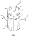
- Figure 1 shows, in partially broken away view, a modular fuel container according to the invention.
- Figures 2 and 3 show, seen in perspective, two complementary elements according to the invention, Figure 2 showing a housing body and Figure 3 a housing cover.
- FIG. 4 represents, in section view, the configuration of the two complementary elements constituting a housing and represented in FIGS. 2 and 3.
- FIG. 5 represents, in section view, another configuration of two complementary elements according to the invention.
- FIG. 6 represents, seen in perspective, a mold for the manufacture by felting of an element blank according to the invention.
- Figure 7 shows, seen in section, the mold of Figure 6 immersed in the felting suspension.
- FIG. 8 represents, in perspective view, the central part of the mold shown in FIGS. 6 and 7.
- FIG. 9 represents, in perspective view, one of the two external shells of the mold shown in FIGS. 6 and 7.
- FIG. 10 is a magnifying glass of part L of FIG. 7.
- the invention relates to fuel container elements for artillery ammunition. We represented in Figures 2 and 4 such an element 1 according to the invention.
- such an element 1 has at least one flat part 2 of revolution having a central orifice 3 bordered by a hollow central neck 4.
- the said central orifice 3 is a circular orifice and the said hollow central neck 4 is a cylindrical neck.
- said plane part 2 of revolution is bordered over its entire periphery by a cylindrical outer wall 5 situated on the same side of said plane part 2 as said central neck 4.
- said outer wall 5 has a height substantially equal to the height of said central neck 4.
- Such an element 1 is intended to constitute the body of a modular combustible container, the outer wall 5 constituting the outer wall of the container housing, the flat part 2 constituting the bottom of the housing and the hollow neck 4 constituting the ignition tube, the wall 5, the flat part 2 and the hollow neck 4 being in one piece.
- FIGS. 3 and 4 show an element 6 complementary to the previous one.
- This element 6 is composed of a flat part 7 of revolution having a circular central orifice 8 bordered by a hollow cylindrical neck 9.
- the flat part 7 of the element 6 is bordered over its entire periphery by an external cylindrical wall 10 located on the same side as the neck 9 and having a height substantially equal to that of the neck 9.
- the outside diameter of the neck 9 of the element 6 is equal to the inside diameter of the neck 4 of the element 1 while the outside diameter of the outside wall 10 of the item 6 is equal to the inside diameter of the outside wall 5 of element 1. It is thus possible to penetrate the neck 9 of the element 6 into the neck 4 of the element 1 so that the end 11 of the neck 4 abuts against the interior surface of the flat part 7 of the element 6. Under these conditions the exterior surface of the wall 10 of the component 6 is in contact with the interior surface of the wall 5 of the component 1.
- the housing body 1 and the element 6 which acts as a cover define a cylindrical housing closed at each of its ends by a flat face having a central orifice, the two central orifices being connected continuously by a channel continuous central constituted by the neck 4 of the element 1 in which the neck 9 of the element 6 is fitted. It is in this sense that the two elements 1 and 6 are said to be complementary in the context of the present invention.
- FIGS. 2, 3 and 4 show a combustible container obtained from two complementary elements 1 and 6 in which the central neck and the outer wall have substantially the same height. Such cases can be easily made integral with each other, for example by using a ring or an adhesive material.
- FIG. 5 shows a section of a fuel container housing made up of two complementary elements 12 and 13.
- the element 12 has a flat part 14 having a circular central orifice 15 bordered by a neck 16 whose height is much less than that of the external wall 17 which borders the flat part 14.
- the element 13 on the contrary has a flat part 18 with a circular central orifice 19 bordered by a neck 20 of height much greater than that of the external wall 21 which borders said flat part 18.
- the inside diameter of the neck 20 is equal to the outside diameter of the neck 16 while the outside diameter of the wall 21 is equal to the inside diameter of the wall 17 so that the element 13 can fit into the element 12 as shown in Figure 5.
- the height of the outer wall 17 of the element 12 is greater than the height of the neck 20 of the element 13, so that the wall 17 extends beyond the part plane 18 of element 13 when the two elements are assembled together, thus defining a hollow ring 22 beyond the plane part 18.
- the outer wall 17 of the element 12 has, on the side of the flat part 14, a constriction 23 of a height and an outer diameter such that the casing thus formed can fit together, by its constriction, in the ring 22 of the previous housing.
- the fuel container elements according to the invention are obtained, as will be explained in detail in the following description, by felting on a liquid-permeable mold of an aqueous suspension consisting mainly of nitrocellulose fibers, cellulose fibers and by a resin, so as to obtain a blank of said element, which blank is then compacted and hot-cooked.
- the aqueous suspension may also contain additives which make it possible to solve the problems of reducing erosion or reducing the migration of nitrated oils.
- the elements of combustible containers, once completed, can receive various types of coatings or varnishes for protection against external agents.
- FIG. 1 shows a modular combustible container 24 obtained from the complementary elements 1 and 6 shown in FIGS. 2, 3 and 4.
- This container 24 was obtained by filling the housing body 1 with a propellant powder 25.
- the filling an element according to the invention with a propellant charge constituted by agglomerated powder or by a bundle of powder strands linked together does not pose any particular problem whatever the configuration of the element.
- a propellant charge constituted by agglomerated powder or by a bundle of powder strands linked together
- the use of 'a housing body as shown in Figure 2 is particularly interesting.
- the complementary elements 1 and 6 shown in Figures 2, 3 and 4 are the preferred elements of the invention.
- the housing body 1 is filled with powder, and it should be observed that it can easily be completely filled, insert the cover 6 as explained above.
- the outside surface of the neck 9 and the outside surface of the wall 10 of the cover 6 will be coated with a little combustible glue to improve the adhesion of the cover to the housing body.
- mechanical locking systems may be preferred.
- a modular combustible container is thus obtained having a central channel defined essentially by the neck 4 of the housing body 1. Before filling the case can be pierced in different places to facilitate ignition or combustion.
- a hollow central channel is imperative to ensure good transmission of ignition from one module to another.
- a complementary hollow ignition tube 26 is introduced into the central channel thus formed.
- this complementary ignition fuel tube 26 bears on the upper end 27 of the neck 9 of the cover 6 and is held in contact with the inside surface of the neck 4 of the housing body 1 by a little combustible glue.
- the complementary ignition tube 26 may consist of a single piece or of several sections placed end to end.
- the ignition tube 26 is obtained by agglomeration under pressure and at a temperature close to 100 ° C. of propellant powder grains coated with a binder based on polyvinyl nitrate according to the techniques described in French patents 2,436,766 and 2,658,505 or in their American correspondents 4 326 901 and 5 174 837.
- a combustible paper reinforcement tube can also be introduced into the ignition tube 26.
- Said propellant powder serving to constitute the tube 26 can advantageously be a powder based on nitrocellulose, porous or non-porous, possibly containing additives. The invention thus makes it possible to be free from any presence of black powder, which reduces the risk of corrosion.
- the tube 26 can also be obtained by agglomeration of the ignition powders for composite powders with low vulnerability.
- the invention also relates to a method of manufacturing by felting of fuel container elements according to the invention and in particular elements as shown in FIG. 2 which have both a very long neck and a very long outer wall.
- Traditional felting techniques according to which solid deposition is carried out on the external surface of a mold immersed in a suspension does not in fact make it possible to obtain hollow cylindrical parts having at their center a central neck of great length which is itself same hollow, the suction in the central cavity of the mold corresponding to said neck only allowing to obtain a full neck, which is not sought in the context of the invention.
- a mold having a cavity of revolution constituted by an outer casing and by a bottom whose surface is flat, the said bottom having a central column, is immersed in the felting suspension.
- Said bottom and said column at less are permeable to liquids and suction is exerted inside the mold.
- the felting suspension is preferably an aqueous suspension consisting mainly of nitrocellulose fibers, cellulose fibers and a resin optionally in the presence of a stabilizer such as diphenylamine.
- a suspension is for example described in patent FR 2,555,302 or in its correspondent US 4,649,827.
- FIGS. 6 to 10 show a mold 28 according to the invention.
- the mold 28 consists of a central part 29 and an external part constituted by two semi-cylindrical shells 30 and 31.
- the central part 29 is connected by a flexible pipe 32 to a vacuum pump while the external shells 30 and 31 are connected to a vacuum pump by flexible pipes 33 and 34.
- a loop flange 35 keeps the shells 30 and 31 tight against each other.
- the central part 29 consists of a cylindrical head 36 traversed by a hollow pipe 37 connected to the pipe 32.
- the head 36 has on its cylindrical face a groove circular 38.
- On the lower flat face of the head 36 is fixed by welding a liquid-permeable filtration grid having a flat circular rim 39 welded to the head 36, a first vertical cylindrical surface 40, an annular flat face 41 finished in its central part by a cylindrical column 42 closed by a bottom 43, thus providing a empty space 44 between the head 36 and the filtration grid.
- the filtration grid constituting the elements 39, 40, 41 42 and 43 is advantageously constituted by a perforated copper grid and covered by an electroformed nickel filter.
- the shell 30 is made up of a solid semi-cylindrical wall 45 traversed by a hollow pipe 46 connected to the pipe 33.
- the interior surface of the wall 45 has a rim 47 intended to penetrate into the groove 38 of the head 36 to ensure the positioning of the shell 30 relative to the head 36.
- the interior surface of the wall 45 has a flat surface 48 having a vertical surface 49 and intended to slide under the head 36, the vertical surface 49 of the flat being of the same height as the vertical surface 40 of the grid carried by the head 36 and coming into abutment against the latter.
- a second flat 50 having a vertical surface 51, the radial depth of the flat 50 being identical to that of the flat 48 so that the vertical surfaces 49 and 51 correspond to a same vertical cylinder.
- a semi-cylindrical filtration grid 52 of the same constitution as the filtration grid carried by the head 36. Thus is created an empty space 53 between the wall 45 and the grid 52.
- the shell 31 is analogous to the shell 30.
- the shells 30 and 31 When they are fixed to the head 36, the shells 30 and 31 define with the latter a cylindrical mold 28 having a cavity of revolution constituted by an envelope composed of the grids 52, of the two shells 30 and 31, by a flat bottom constitutes itself by the flat face 41 of the grid carried by the head 36 and by a column itself constituted by the parts 42 and 43 of the grid carried by the head 36.
- the mold shown in Figures 7 to 10 is intended to obtain a part as shown in Figure 2, the envelope formed by the grids 52 being in this case permeable to liquids. To obtain other configurations, this envelope may only be partially permeable to liquids.
- the length of the grid 52 between the flats 48 and 50 as well as the length of the part 42 of the grid carried by the head 36 will be slightly greater than the final dimensions of the element that l 'we want to get.
- a blank 55 is deposited along the filtration grids.
- This blank has the general shape of the element 1 shown in FIG. 2, but its hollow neck 4 is closed by the deposition of fibers on the surface 43 of the filtration grid carried by the head 36.
- the mold is removed from the aqueous suspension and the blank 55 undergoes a first dehydration under vacuum on the mold. Then the shells 30 and 31 are removed and the blank 55 is removed from the mold to undergo compaction and hot cooking on a shaping mold, according to techniques known to those skilled in the art. After cooking the element is cut to the desired length, which has the effect of opening the central neck which until then was closed.
- the elements according to the invention thus make it possible to simply obtain modular combustible containers for medium and large caliber artillery ammunition which can be completely and easily loaded with the different geometries of propellant powders existing on the market.
- a combustible case body and a cover were made in accordance with Figures 2 and 3.
- the housing body was filled with 2450 g of a double base powder (nitrocellulose / nitroglycerine) in the form of cylindrical grains with 19 holes of potential 900 cal / g or 3780 d / g (or 2700 g of this same powder in the form of divided strands ).
- a double base powder nitrocellulose / nitroglycerine
- An ignition tube obtained from a single base porous nitrocellulose powder coated with 3% binder or polyvinyl nitrate was introduced into the central channel of the container thus formed.
- This tube has an apparent density of 0.77 g / cm3.
- a combustible container was introduced as described above, loaded with powdered grains with 19 holes.
Landscapes
- Engineering & Computer Science (AREA)
- General Engineering & Computer Science (AREA)
- Manufacturing & Machinery (AREA)
- Details Of Rigid Or Semi-Rigid Containers (AREA)
- Containers And Packaging Bodies Having A Special Means To Remove Contents (AREA)
- Cooling, Air Intake And Gas Exhaust, And Fuel Tank Arrangements In Propulsion Units (AREA)
Applications Claiming Priority (2)
| Application Number | Priority Date | Filing Date | Title |
|---|---|---|---|
| FR9311829A FR2710976B1 (fr) | 1993-10-05 | 1993-10-05 | Eléments de conteneurs combustibles pour munitions d'artillerie, procédé de fabrication et utilisation de tels éléments. |
| FR9311829 | 1993-10-05 |
Publications (2)
| Publication Number | Publication Date |
|---|---|
| EP0646762A1 true EP0646762A1 (de) | 1995-04-05 |
| EP0646762B1 EP0646762B1 (de) | 1998-03-25 |
Family
ID=9451536
Family Applications (1)
| Application Number | Title | Priority Date | Filing Date |
|---|---|---|---|
| EP94402205A Expired - Lifetime EP0646762B1 (de) | 1993-10-05 | 1994-10-04 | Verbrennbare Hulsenteile für Artilleriegeschosse, Verfahren zu deren Herstellung und Verwendung derselben |
Country Status (4)
| Country | Link |
|---|---|
| US (1) | US5454323A (de) |
| EP (1) | EP0646762B1 (de) |
| DE (1) | DE69409194T2 (de) |
| FR (1) | FR2710976B1 (de) |
Cited By (4)
| Publication number | Priority date | Publication date | Assignee | Title |
|---|---|---|---|---|
| FR2781879A1 (fr) * | 1998-07-30 | 2000-02-04 | Giat Ind Sa | Element de charge propulsive et son procede de fabrication |
| FR3050521A1 (fr) * | 2016-04-26 | 2017-10-27 | Nexter Munitions | Sac de poudre propulsive, charge propulsive d'artillerie incorporant un tel sac et procede de fabrication |
| RU2662537C1 (ru) * | 2017-10-05 | 2018-07-26 | Федеральное казенное предприятие "Государственный научно-исследовательский институт химических продуктов" (ФКП "ГосНИИХП") | Жесткий сгорающий картуз для метательных зарядов минометных выстрелов |
| FR3164782A1 (fr) | 2024-07-22 | 2026-01-23 | Eurenco France Sas | Conteneur combustible de longueur modulable et son relais d'allumage pour charge propulsive. |
Families Citing this family (22)
| Publication number | Priority date | Publication date | Assignee | Title |
|---|---|---|---|---|
| DE4445991A1 (de) * | 1994-12-22 | 1996-06-27 | Rheinmetall Ind Gmbh | Anzündsystem für Treibladungen und Verfahren zur Herstellung derartiger Anzündsysteme |
| FR2736425B1 (fr) * | 1995-07-07 | 1997-08-29 | Giat Ind Sa | Conteneur combustible de charge propulsive pour une munition d'artillerie de campagne |
| US5763816A (en) * | 1996-07-26 | 1998-06-09 | Slurry Explosive Corporation | Explosive primer |
| US5747723A (en) * | 1996-11-26 | 1998-05-05 | The United States Of America As Represented By The Secretary Of The Army | Modular artillery charge system |
| SE519296C2 (sv) * | 1997-08-14 | 2003-02-11 | Bofors Defence Ab | Drivladdningsmodul |
| US6360666B1 (en) | 2000-06-06 | 2002-03-26 | Alliant Techsystems Inc. | Alignment fixture |
| US6343552B1 (en) | 2000-06-06 | 2002-02-05 | Alliant Techsystems Inc. | Solvent application system |
| US6382104B1 (en) * | 2000-11-07 | 2002-05-07 | The United States Of America As Represented By The Secretary Of The Navy | Two-piece base pad igniter bag |
| US7546804B1 (en) * | 2006-10-10 | 2009-06-16 | The United States Of America As Represented By The Secretary Of The Army | Artillery charge with laser ignition |
| JP5814514B2 (ja) * | 2010-04-07 | 2015-11-17 | 旭化成ケミカルズ株式会社 | 簡便な構造の焼尽性容器 |
| US8915004B1 (en) | 2011-10-24 | 2014-12-23 | F. Richard Langner | Systems and methods for a firing pin |
| US9322625B1 (en) | 2011-10-24 | 2016-04-26 | F. Richard Langner | Systems and methods for launching water from a disrupter cannon |
| US9200881B1 (en) | 2011-10-24 | 2015-12-01 | F. Richard Langner | Systems and methods for an improved firing assembly |
| JP6411078B2 (ja) * | 2014-06-05 | 2018-10-24 | 日油技研工業株式会社 | 焼尽性材料 |
| RU2597120C2 (ru) * | 2015-01-26 | 2016-09-10 | Федеральное казенное предприятие "Государственный научно-исследовательский институт химических продуктов" (ФКП "ГосНИИХП") | Материал повышенной термостойкости жесткого сгорающего картуза |
| US9625242B1 (en) * | 2015-02-12 | 2017-04-18 | The United States Of America As Represented By The Secretary Of The Army | Igniter for modular artillery charge system |
| DE102016112510A1 (de) * | 2016-07-07 | 2018-01-11 | Krauss-Maffei Wegmann Gmbh & Co. Kg | Verfahren und Vorrichtung zur Temperaturermittlung sowie Verfahren und Vorrichtung zum Fügen von Treibladungsmodulen |
| US10107607B1 (en) | 2017-04-04 | 2018-10-23 | The United States Of America As Represented By The Secretary Of The Army | Radio frequency igniter |
| US10495425B1 (en) * | 2018-10-04 | 2019-12-03 | United States Of America, As Represented By The Secretary Of The Navy | Thermoformed projectile cartridge |
| US10969206B1 (en) | 2018-11-29 | 2021-04-06 | U.S. Government As Represented By The Secretary Of The Army | Radio frequency antenna for use in the confines of a breech |
| KR102177959B1 (ko) * | 2019-06-18 | 2020-11-12 | 국방과학연구소 | 단위장약용 일체형 점화기 |
| FR3115869B1 (fr) | 2020-11-04 | 2022-11-11 | Eurenco France | Procede de fabrication d'un boitier renfermant un chargement pyrotechnique |
Citations (6)
| Publication number | Priority date | Publication date | Assignee | Title |
|---|---|---|---|---|
| BE686182A (de) * | 1965-08-31 | 1967-02-01 | ||
| US3474702A (en) * | 1965-12-16 | 1969-10-28 | Us Army | Felting process for making combustible cartridge cases |
| US3550532A (en) * | 1967-08-25 | 1970-12-29 | Theodore Zimmerman | Moisture-proof combustible cartridge case |
| WO1986001584A1 (fr) * | 1984-09-01 | 1986-03-13 | Rheinmetall Gmbh | Module propulseur |
| US5052304A (en) * | 1989-07-28 | 1991-10-01 | Rheinmetall Gmbh | Propelling charge container |
| EP0475207A1 (de) * | 1990-08-30 | 1992-03-18 | Olin Corporation | Hülsenloses einheitsliches Ammunitionsladungsmodul |
Family Cites Families (4)
| Publication number | Priority date | Publication date | Assignee | Title |
|---|---|---|---|---|
| DE4124657A1 (de) * | 1991-07-25 | 1993-01-28 | Rheinmetall Gmbh | Modulare treibladung |
| JPH05105572A (ja) * | 1991-10-22 | 1993-04-27 | Daicel Chem Ind Ltd | 中心点火薬円筒 |
| JP3192181B2 (ja) * | 1991-10-28 | 2001-07-23 | 旭化成株式会社 | ユニット型発射装薬 |
| JPH05118792A (ja) * | 1991-10-28 | 1993-05-14 | Asahi Chem Ind Co Ltd | ユニツト発射装薬 |
-
1993
- 1993-10-05 FR FR9311829A patent/FR2710976B1/fr not_active Expired - Lifetime
-
1994
- 1994-09-28 US US08/314,157 patent/US5454323A/en not_active Expired - Lifetime
- 1994-10-04 EP EP94402205A patent/EP0646762B1/de not_active Expired - Lifetime
- 1994-10-04 DE DE69409194T patent/DE69409194T2/de not_active Expired - Lifetime
Patent Citations (6)
| Publication number | Priority date | Publication date | Assignee | Title |
|---|---|---|---|---|
| BE686182A (de) * | 1965-08-31 | 1967-02-01 | ||
| US3474702A (en) * | 1965-12-16 | 1969-10-28 | Us Army | Felting process for making combustible cartridge cases |
| US3550532A (en) * | 1967-08-25 | 1970-12-29 | Theodore Zimmerman | Moisture-proof combustible cartridge case |
| WO1986001584A1 (fr) * | 1984-09-01 | 1986-03-13 | Rheinmetall Gmbh | Module propulseur |
| US5052304A (en) * | 1989-07-28 | 1991-10-01 | Rheinmetall Gmbh | Propelling charge container |
| EP0475207A1 (de) * | 1990-08-30 | 1992-03-18 | Olin Corporation | Hülsenloses einheitsliches Ammunitionsladungsmodul |
Cited By (5)
| Publication number | Priority date | Publication date | Assignee | Title |
|---|---|---|---|---|
| FR2781879A1 (fr) * | 1998-07-30 | 2000-02-04 | Giat Ind Sa | Element de charge propulsive et son procede de fabrication |
| FR3050521A1 (fr) * | 2016-04-26 | 2017-10-27 | Nexter Munitions | Sac de poudre propulsive, charge propulsive d'artillerie incorporant un tel sac et procede de fabrication |
| RU2662537C1 (ru) * | 2017-10-05 | 2018-07-26 | Федеральное казенное предприятие "Государственный научно-исследовательский институт химических продуктов" (ФКП "ГосНИИХП") | Жесткий сгорающий картуз для метательных зарядов минометных выстрелов |
| FR3164782A1 (fr) | 2024-07-22 | 2026-01-23 | Eurenco France Sas | Conteneur combustible de longueur modulable et son relais d'allumage pour charge propulsive. |
| WO2026022439A1 (fr) | 2024-07-22 | 2026-01-29 | Eurenco France Sas | Conteneur combustible de longueur modulable et son relais d'allumage pour charge propulsive |
Also Published As
| Publication number | Publication date |
|---|---|
| EP0646762B1 (de) | 1998-03-25 |
| FR2710976A1 (fr) | 1995-04-14 |
| US5454323A (en) | 1995-10-03 |
| FR2710976B1 (fr) | 1995-11-17 |
| DE69409194T2 (de) | 1998-07-30 |
| DE69409194D1 (de) | 1998-04-30 |
Similar Documents
| Publication | Publication Date | Title |
|---|---|---|
| EP0646762B1 (de) | Verbrennbare Hulsenteile für Artilleriegeschosse, Verfahren zu deren Herstellung und Verwendung derselben | |
| FR2526151A1 (fr) | Munition encartouchee constituee par un projectile et une douille combustible ou partiellement combustible reliee a celui-ci | |
| FR2712218A1 (fr) | Pièce en métal ou en céramique à coque extérieure dense et à âme poreuse, ainsi que son procédé de fabrication. | |
| FR2602266A1 (fr) | Ensemble de rotor de turbomoteur a gaz | |
| EP0706025A1 (de) | Patronenhülse für eine Treibladung | |
| EP0684443B1 (de) | Vorrichtung zum Verbinden von zwei Behältern und Behälter dafür | |
| EP0499500B1 (de) | Behälter, vorgesehen mit elektrischen Verbindungsmitteln | |
| EP0949224B1 (de) | Verfahren zur Herstellung eines Objektes aus körnigem Material und nach diesem Verfahren hergestelltes Zündrohr und Treibsatz | |
| FR2713662A1 (fr) | Procédé d'obtention d'une pièce circulaire métallique renforcée par des fibres. | |
| EP0010459B1 (de) | Vorrichtung und Verfahren zur Herstellung von Elementen aus agglomeriertem Treibpulver; so hergestellte Elemente | |
| EP0314547B1 (de) | Treibladung für flügelstabilisierte Geschossmunition sowie Verfahren zu ihrer Herstellung | |
| EP0238409B1 (de) | Verfahren zum Herstellen von brennbaren Gegenständen durch Tiefziehen von brennbaren Papierscheiben mit einer elastischen Patrize und Vorrichtung zum Durchführen des Verfahrens | |
| FR2714168A1 (fr) | Procédé de fabrication de conteneur pour charge propulsive et conteneur ainsi obtenu. | |
| EP4241038B1 (de) | Verfahren zur herstellung eines eine pyrotechnische ladung umschliessenden gehäuses | |
| WO2026022439A1 (fr) | Conteneur combustible de longueur modulable et son relais d'allumage pour charge propulsive | |
| FR2676050A1 (fr) | Support en materiau ceramique pour un element accumulateur electrochimique de puissance et son procede de fabrication. | |
| BE1010999A5 (fr) | Piston. | |
| EP0757223B1 (de) | Behälter für Munition für Artillerie mit selbstverbrennender Patronenhülse | |
| EP0519798B1 (de) | Verfahren zur Herstellung einer Hochleistung-Sprengladung und Vorrichtung zur Durchführung dieses Verfahren | |
| WO1993006255A1 (fr) | Procede de realisation d'une piece composite a surface antiabrasion, et pieces obtenues par ce procede | |
| WO2014195650A1 (fr) | Chargement pyrotechnique et generateur de gaz comprenant un tel chargement | |
| FR2617586A1 (fr) | Enveloppe de projectile | |
| FR2713328A1 (fr) | Conteneur pour charge propulsive pouvant être rendu solidaire d'un autre conteneur. | |
| FR2737002A1 (fr) | Systeme d'allumage d'une charge propulsive, notamment pour munition d'artillerie de campagne, et son procede de fabrication | |
| EP0147314B1 (de) | Kunststoffbodenkörper |
Legal Events
| Date | Code | Title | Description |
|---|---|---|---|
| PUAI | Public reference made under article 153(3) epc to a published international application that has entered the european phase |
Free format text: ORIGINAL CODE: 0009012 |
|
| AK | Designated contracting states |
Kind code of ref document: A1 Designated state(s): BE DE GB IT |
|
| 17P | Request for examination filed |
Effective date: 19951005 |
|
| GRAG | Despatch of communication of intention to grant |
Free format text: ORIGINAL CODE: EPIDOS AGRA |
|
| 17Q | First examination report despatched |
Effective date: 19970619 |
|
| GRAG | Despatch of communication of intention to grant |
Free format text: ORIGINAL CODE: EPIDOS AGRA |
|
| GRAG | Despatch of communication of intention to grant |
Free format text: ORIGINAL CODE: EPIDOS AGRA |
|
| GRAH | Despatch of communication of intention to grant a patent |
Free format text: ORIGINAL CODE: EPIDOS IGRA |
|
| GRAH | Despatch of communication of intention to grant a patent |
Free format text: ORIGINAL CODE: EPIDOS IGRA |
|
| GRAA | (expected) grant |
Free format text: ORIGINAL CODE: 0009210 |
|
| AK | Designated contracting states |
Kind code of ref document: B1 Designated state(s): BE DE GB IT |
|
| ITF | It: translation for a ep patent filed | ||
| GBT | Gb: translation of ep patent filed (gb section 77(6)(a)/1977) |
Effective date: 19980326 |
|
| REF | Corresponds to: |
Ref document number: 69409194 Country of ref document: DE Date of ref document: 19980430 |
|
| PLBE | No opposition filed within time limit |
Free format text: ORIGINAL CODE: 0009261 |
|
| STAA | Information on the status of an ep patent application or granted ep patent |
Free format text: STATUS: NO OPPOSITION FILED WITHIN TIME LIMIT |
|
| 26N | No opposition filed | ||
| REG | Reference to a national code |
Ref country code: GB Ref legal event code: IF02 |
|
| PGFP | Annual fee paid to national office [announced via postgrant information from national office to epo] |
Ref country code: GB Payment date: 20031001 Year of fee payment: 10 |
|
| PGFP | Annual fee paid to national office [announced via postgrant information from national office to epo] |
Ref country code: BE Payment date: 20031219 Year of fee payment: 10 |
|
| REG | Reference to a national code |
Ref country code: GB Ref legal event code: 732E |
|
| PG25 | Lapsed in a contracting state [announced via postgrant information from national office to epo] |
Ref country code: GB Free format text: LAPSE BECAUSE OF NON-PAYMENT OF DUE FEES Effective date: 20041004 |
|
| PG25 | Lapsed in a contracting state [announced via postgrant information from national office to epo] |
Ref country code: BE Free format text: LAPSE BECAUSE OF NON-PAYMENT OF DUE FEES Effective date: 20041031 |
|
| BERE | Be: lapsed |
Owner name: *SNPE MATERIAUX ENERGETIQUES Effective date: 20041031 |
|
| GBPC | Gb: european patent ceased through non-payment of renewal fee |
Effective date: 20041004 |
|
| PG25 | Lapsed in a contracting state [announced via postgrant information from national office to epo] |
Ref country code: IT Free format text: LAPSE BECAUSE OF NON-PAYMENT OF DUE FEES;WARNING: LAPSES OF ITALIAN PATENTS WITH EFFECTIVE DATE BEFORE 2007 MAY HAVE OCCURRED AT ANY TIME BEFORE 2007. THE CORRECT EFFECTIVE DATE MAY BE DIFFERENT FROM THE ONE RECORDED. Effective date: 20051004 |
|
| BERE | Be: lapsed |
Owner name: *SNPE MATERIAUX ENERGETIQUES Effective date: 20041031 |
|
| PGFP | Annual fee paid to national office [announced via postgrant information from national office to epo] |
Ref country code: DE Payment date: 20131004 Year of fee payment: 20 |
|
| REG | Reference to a national code |
Ref country code: DE Ref legal event code: R071 Ref document number: 69409194 Country of ref document: DE |