EP0646943A2 - Tube à rayons cathodiques couleurs - Google Patents
Tube à rayons cathodiques couleurs Download PDFInfo
- Publication number
- EP0646943A2 EP0646943A2 EP94115209A EP94115209A EP0646943A2 EP 0646943 A2 EP0646943 A2 EP 0646943A2 EP 94115209 A EP94115209 A EP 94115209A EP 94115209 A EP94115209 A EP 94115209A EP 0646943 A2 EP0646943 A2 EP 0646943A2
- Authority
- EP
- European Patent Office
- Prior art keywords
- mask body
- effective area
- reinforcing bead
- mask
- ray tube
- Prior art date
- Legal status (The legal status is an assumption and is not a legal conclusion. Google has not performed a legal analysis and makes no representation as to the accuracy of the status listed.)
- Granted
Links
Images
Classifications
-
- H—ELECTRICITY
- H01—ELECTRIC ELEMENTS
- H01J—ELECTRIC DISCHARGE TUBES OR DISCHARGE LAMPS
- H01J29/00—Details of cathode-ray tubes or of electron-beam tubes of the types covered by group H01J31/00
- H01J29/02—Electrodes; Screens; Mounting, supporting, spacing or insulating thereof
- H01J29/06—Screens for shielding; Masks interposed in the electron stream
- H01J29/07—Shadow masks for colour television tubes
Definitions
- the present invention relates to a color cathode-ray tube and, more particularly, to a color cathode-ray tube in which a reinforcing bead is formed on the effective area of a shadow mask to improve the mechanical strength of the shadow mask.
- a color cathode-ray tube has an envelope constituted by a substantially rectangular spherical panel and a funnel integrally bonded to this panel.
- a phosphor screen comprising dots or stripes of three-color phosphor layers that emit blue, green, and red light components is formed on the inner surface of the panel.
- a rectangular shadow mask is arranged on the inner side of the phosphor screen to oppose it.
- the shadow mask has a rectangular mask body and a mask frame attached to the skirt portion of the mask body.
- the mask body has a rectangular effective area which is formed spherically to have a predetermined radius of curvature and in which a large number of electron beam apertures are formed with a predetermined arrangement, and a non-effective area which is located around the effective area and in which no electron beam apertures are formed.
- the skirt portion is formed continuously to the non-effective area.
- the shadow mask is supported on the inner side of the panel such that its effective area opposes the phosphor screen, by engaging a frame holder, attached to the mask frame, with stud pins provided on the panel.
- An electron gun for emitting three electron beams toward the phosphor screen is disposed in the neck of the funnel.
- the shadow mask serves to select three electron beams emitted from the electron gun so that they are correctly land on the corresponding ones of the three-color phosphor layers.
- the three electron beams emitted from the electron gun are deflected by a magnetic field generated by a deflecting yoke which is mounted on the outer surface of the funnel, and the deflected electron beams are selected by the shadow mask to scan the phosphor screen in the horizontal and vertical directions, thereby displaying a color image.
- the present invention has been made in view of the above problems, and has its object to provide a color cathode-ray tube in which doming of the shadow mask is sufficiently suppressed, thereby preventing a degradation in outer appearance of the phosphor screen and the degradation in image quality.
- a color cathode-ray tube comprising: a face panel having a phosphor screen formed on an inner surface thereof; and a shadow mask disposed to oppose the phosphor screen at a predetermined gap.
- the shadow mask comprises: a mask body having a substantially rectangular effective area having a large number of electron beam apertures through which electron beams pass, a non-effective area surrounding the effective area, and a skirt portion extending from the peripheral portion of the non-effective area; and a mask frame mounted on the skirt portion of the mask body.
- the mask body has a center coinciding with a tube axis, horizontal and vertical axes extending through the center, and a belt-shaped reinforcing bead extending between two end edges of the mask body, with respect to the horizontal axis, through a central portion of the mask body and projecting from the effective area toward the phosphor screen.
- the reinforcing bead is formed such that its projecting height is gradually decreased from the central portion of the mask body toward the two end edges of the mask body, and such that its projecting height at boundaries between the effective and non-effective areas become about 2/3 or less the height of the reinforcing bead at the central portion of the mask body.
- the reinforcing bead is formed such that its projecting height h at the central portion of the mask body satisfies 0.1t ⁇ h ⁇ 3t where t is the thickness of the mask body.
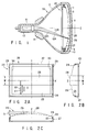
- FIGS. 1 to 6 show a color cathode ray tube according to an embodiment of the present invention, in which:
- the color cathode-ray tube has an envelope 50 comprising a rectangular spherical face panel 1 and a funnel 2 integrally bonded to the face panel 1.
- a phosphor screen 3 comprising vertically elongated stripes of three-color phosphor layers that emit blue, green, and red light components.
- a rectangular shadow mask 20 is arranged on the inner side of the phosphor screen 3 to oppose it.
- An electron gun 13 for emitting three electron beams 12B, and 12G, and 12R that are arranged in a row to travel on the same horizontal plane is disposed in a neck 11 of the funnel 2.
- the three electron beams 12B, 12G, and 12R emitted from the electron gun 13 are deflected by a magnetic field generated by a deflecting yoke 14 mounted on the outer surface of the funnel 2, and the deflected electron beams scan the phosphor screen 3 through the shadow mask 20 in the horizontal and vertical directions, thereby displaying a color image.
- the shadow mask 20 has a substantially rectangular mask body 26 and a mask frame 27 on which the mask body 26 is mounted.
- the mask body 26 has a rectangular effective area 23 in which a large number of electron beam apertures are formed for passing the electron beams therethrough, a non-effective area 24 (a portion where electron beam apertures are not formed) surrounding the effective area 23, and a skirt portion 25 extending from the peripheral portion of the non-effective area 24 and fixed to the mask frame 27.
- the effective and non-effective areas 23 and 24 form a rectangular spherical portion as a whole which has a predetermined radius of curvature.
- the mask body 26 has a mask center through which the tube axis Z of the color cathode-ray tube extends, a horizontal axis (X-axis) extending through the mask center, and a vertical axis (Y-axis) extending through the mask center and perpendicular to the horizontal axis.
- a large number of electron beam apertures 21 formed in the effective area 23 are arranged by aligning a plurality of vertical arrays, each obtained by arranging a plurality of electron beam apertures 21 in the Y-axis direction through bridges 22 having narrow width, in the horizontal direction (X-axis direction).
- the shadow mask 20 having the above arrangement is supported on the inner side of the face panel 1 by coupling frame holders 9, constituted by elastic members and mounted on the mask frame 27, with stud pins 10 fixed to the face panel 1, such that the mask body 26 opposes the phosphor screen 3.
- a belt-shaped reinforcing bead 28 having a width W is formed on the mask body 26 of the shadow mask 20 and extends between the two end edges of the mask body 26 which are in parallel to the Y-axis.
- the reinforcing bead 28 is formed at the central portion of the mask body 26 to be parallel to the X-axis, so that it traverses the effective area 23 and the non-effective area 24 surrounding the effective area 23 in the horizontal direction.
- the reinforcing bead 28 projects from the front surface of the mask body 26 toward the phosphor screen.
- the reinforcing bead 28 is formed such that its height h is gradually decreased from the central portion of the effective area 23 toward the respective boundaries 29 to be 0 at the respective boundaries 29.
- the height h of the reinforcing bead 28 at boundaries 30 between the effective and non-effective areas 23 and 24 is 2/3 or less the height h of the reinforcing bead 28 at the central portion of the effective area 23.
- the height h of the reinforcing bead 28 at the central portion of the effective area 23 is set to satisfy the following relationship: 0.1t ⁇ h ⁇ 3t where t is the thickness of the mask body 26.
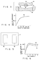
- the mask body 26 having the above arrangement is fabricated by press-molding a flat mask, in which electron beam apertures are formed by photoetching, with a pressing unit, as shown in FIG. 3.
- the pressing unit has a punch 33 in which a molding die 32 for molding the reinforcing bead is mounted on a molding surface 31 that molds the effective area and the non-effective area surrounding the effective area, and a die 36 in which a recessed portion 35 corresponding to the molding die 32 that molds the reinforcing bead is formed in a molding surface 34 having the same radius of curvature as that of the molding surface 31 of the punch 33.
- the pressing unit press-molds the flat mask between the punch 33 and the die 36.
- the skirt portion 25 of the press-molded mask body 26 is welded to the mask frame 27 which is separately molded, thereby forming the shadow mask 20.
- the reinforcing bead 28 the height h of which is gradually decreased from the central portion of the effective area 23 toward the boundaries 29 between the non-effective area 24 and the skirt portion 25 to become 0 at the boundaries 29, is formed on the mask body 26 of the shadow mask 20, and the height h of the reinforcing bead 28 at the central portion of the effective area 23 is regulated to satisfy the relationship of 0.1t ⁇ h ⁇ 3t, where t is the thickness of the mask body 26, as described above.
- the arrangement of the phosphor layers is disordered at the peripheral portion of the phosphor screen which is formed by photographic printing that uses the shadow mask as the photomask, and the quality of the outer appearance of the phosphor screen is degraded.
- the difference in height between the effective area 23 and the reinforcing bead 28 at the peripheral portion of the effective area 23 becomes small, while a strength of the shadow mask 20 necessary for doming suppression of the shadow mask can be maintained, and a disorder in arrangement of the phosphor layers at the peripheral portion of the phosphor screen can be decreased, thereby decreasing a degradation in quality of the outer appearance of the phosphor screen. Also, beam landing errors at the peripheral portion of the phosphor screen 3 can also be decreased, so that a degradation in image quality can also be prevented.
- the shadow mask can sufficiently suppress doming.
- the relationship between the height h of the reinforcing bead 28 and a purity drift (PD) caused by doming of the shadow mask is represented by a curve 38 shown in FIG. 4.
- the height h of the reinforcing bead 28 becomes 0.3 mm or more, the purity drift is not much improved for an increase in height h of the reinforcing bead.
- the height h of the reinforcing bead 28 is increased, the disorder in arrangement of the phosphor layers becomes large not only at the peripheral portion of the phosphor screen but also at the intermediate and central portions of the phosphor screen, leading to an increase in beam landing errors. Therefore, the height h of the reinforcing bead 28 is 3t at maximum.
- the purity drifts of 19- and 21-inch color cathode-ray tubes were measured.
- a shadow mask having a reinforcing bead having a height h of 0.15 mm and a shadow mask having no reinforcing bead were used, and white images 39 having a predetermined size were drawn at the right and left portions of each phosphor screen 3, as shown in FIG. 5, in the same manner as in the conventional forced purity drift test.
- FIG. 6 shows the results. Referring to FIG. 6, a curve 40 represents the purity drift of the shadow mask having a reinforcing bead, and a curve 41 represents the purity drift of the shadow mask having no reinforcing bead.
- the purity drift was greatly improved by providing a reinforcing bead 28 to the shadow mask.
- a change in purity drift of the color cathode-ray tube having a reinforcing bead was improved by about 13% that of the color cathode-ray tube not having a reinforcing bead.
- the reinforcing bead traversing the effective area in the horizontal direction is formed on the mask body, such that its height h is gradually decreased from the central portion of the effective area toward the boundaries between the non-effective area and the skirt portion to be 0 at the boundaries.
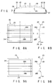
- the reinforcing bead may be formed as shown in FIG. 7. More specifically, according to the first modification shown in FIG. 7, a reinforcing bead 28 is formed like a belt extending between the two end edges of an effective area 23 with respect to the horizontal direction along the horizontal axis (X-axis).
- a height h of the reinforcing bead 28 is constant from the central portion of the effective area 23 toward portions 43 in the vicinities of the two end edges of the effective area 23 in the horizontal direction, and is gradually decreased from the portions 43 toward the two end edges of the effective area 23 in the horizontal direction, i.e., toward boundaries 30 between the effective and non-effective areas 23 and 24, to be 0 at the boundaries 30.
- doming of the shadow mask can be sufficiently suppressed, and a disorder in arrangement of the phosphor layers at the peripheral portion of the phosphor screen can be decreased, in the same manner as in the first embodiment described above, thereby improving the image quality.
- the number of the reinforcing beads 28 is not limited to one, but a plurality of reinforcing beads 28 may be formed.
- a plurality of (two in FIGS. 8A and 8B) comparatively narrow reinforcing beads 28a and 28b may be formed to traverse an effective area 23 in the horizontal direction.
- the reinforcing beads 28a and 28b may be formed to have comparatively large widths. It must be noted that the arrangement and shape of each of the reinforcing beads 28a and 28b must be the same as those of either the first embodiment or the first modification described above.
Landscapes
- Electrodes For Cathode-Ray Tubes (AREA)
Applications Claiming Priority (2)
| Application Number | Priority Date | Filing Date | Title |
|---|---|---|---|
| JP243475/93 | 1993-09-30 | ||
| JP24347593 | 1993-09-30 |
Publications (3)
| Publication Number | Publication Date |
|---|---|
| EP0646943A2 true EP0646943A2 (fr) | 1995-04-05 |
| EP0646943A3 EP0646943A3 (fr) | 1995-11-29 |
| EP0646943B1 EP0646943B1 (fr) | 1997-11-26 |
Family
ID=17104446
Family Applications (1)
| Application Number | Title | Priority Date | Filing Date |
|---|---|---|---|
| EP94115209A Expired - Lifetime EP0646943B1 (fr) | 1993-09-30 | 1994-09-27 | Tube à rayons cathodiques couleurs |
Country Status (6)
| Country | Link |
|---|---|
| US (1) | US5506466A (fr) |
| EP (1) | EP0646943B1 (fr) |
| KR (1) | KR0130026B1 (fr) |
| DE (1) | DE69407018T2 (fr) |
| MY (1) | MY111458A (fr) |
| TW (1) | TW305477U (fr) |
Families Citing this family (9)
| Publication number | Priority date | Publication date | Assignee | Title |
|---|---|---|---|---|
| KR100322677B1 (ko) * | 1995-10-19 | 2002-07-31 | 엘지전자주식회사 | 칼라음극선관용새도우마스크구조 |
| JPH11185650A (ja) | 1997-12-18 | 1999-07-09 | Toshiba Corp | カラー受像管 |
| KR100366078B1 (ko) * | 1999-10-04 | 2002-12-26 | 삼성에스디아이 주식회사 | 새도우 마스크 |
| KR100648712B1 (ko) * | 2000-01-03 | 2006-11-23 | 삼성에스디아이 주식회사 | 칼라 음극선관 |
| JP2003016959A (ja) * | 2001-07-02 | 2003-01-17 | Hitachi Ltd | カラー陰極線管 |
| JP2006049145A (ja) * | 2004-08-05 | 2006-02-16 | Matsushita Toshiba Picture Display Co Ltd | カラー受像管 |
| JP2006059574A (ja) * | 2004-08-17 | 2006-03-02 | Matsushita Toshiba Picture Display Co Ltd | カラー受像管 |
| US7242137B2 (en) * | 2004-09-30 | 2007-07-10 | Matsushita Toshiba Picture Display Co., Ltd. | Cathode ray tube with cone having non-circular cross-section |
| US20060087215A1 (en) * | 2004-10-22 | 2006-04-27 | Matsushita Toshiba Picture Display Co., Ltd. | Cathode ray tube |
Family Cites Families (9)
| Publication number | Priority date | Publication date | Assignee | Title |
|---|---|---|---|---|
| US3944867A (en) * | 1974-03-15 | 1976-03-16 | Zenith Radio Corporation | Shadow mask having ribs bounding rectangular apertures |
| US4173729A (en) * | 1977-06-24 | 1979-11-06 | Rca Corporation | Cathode-ray tube having a stepped shadow mask |
| US4122368A (en) * | 1977-07-08 | 1978-10-24 | Rca Corporation | Cathode ray tube with a corrugated mask having a corrugated skirt |
| JPS604364Y2 (ja) * | 1981-05-08 | 1985-02-07 | ソニー株式会社 | 陰極線管 |
| JPH0775144B2 (ja) * | 1985-04-17 | 1995-08-09 | ソニー株式会社 | 陰極線管の色選別電極 |
| JPH05121008A (ja) * | 1991-10-24 | 1993-05-18 | Sony Corp | 陰極線管色選別機構 |
| US5394051A (en) * | 1992-12-28 | 1995-02-28 | Zenith Electronics Corporation | Vibration-damping configuration in a strip shadow mask |
| US5391957A (en) * | 1992-12-28 | 1995-02-21 | Zenith Electronics Corporation | Vibration damping means for a strip shadow mask |
| JPH06267448A (ja) * | 1993-03-15 | 1994-09-22 | Hitachi Ltd | カラー陰極線管 |
-
1994
- 1994-09-22 TW TW085200203U patent/TW305477U/zh unknown
- 1994-09-24 MY MYPI94002545A patent/MY111458A/en unknown
- 1994-09-27 EP EP94115209A patent/EP0646943B1/fr not_active Expired - Lifetime
- 1994-09-27 DE DE69407018T patent/DE69407018T2/de not_active Expired - Fee Related
- 1994-09-29 KR KR1019940025420A patent/KR0130026B1/ko not_active Expired - Fee Related
- 1994-09-29 US US08/314,690 patent/US5506466A/en not_active Expired - Fee Related
Also Published As
| Publication number | Publication date |
|---|---|
| MY111458A (en) | 2000-05-31 |
| KR0130026B1 (ko) | 1998-04-07 |
| US5506466A (en) | 1996-04-09 |
| EP0646943B1 (fr) | 1997-11-26 |
| KR950009861A (ko) | 1995-04-26 |
| EP0646943A3 (fr) | 1995-11-29 |
| DE69407018D1 (de) | 1998-01-08 |
| DE69407018T2 (de) | 1998-05-07 |
| TW305477U (en) | 1997-05-11 |
Similar Documents
| Publication | Publication Date | Title |
|---|---|---|
| CA1086810A (fr) | Tube cathodique couleur a ecran de phosphore raye | |
| EP0304922B1 (fr) | Tube-image couleur | |
| JP2534644B2 (ja) | カラ−受像管 | |
| EP0646943B1 (fr) | Tube à rayons cathodiques couleurs | |
| US4983879A (en) | Shadow mask type color cathode ray tube with shadow mask effective to minimize the appearance of Moire patterns | |
| EP0655762A1 (fr) | Tube à rayons cathodiques couleur | |
| US5554909A (en) | One dimensional tension mask-frame assembly for CRT | |
| US6124668A (en) | Color cathode ray tube | |
| KR100210566B1 (ko) | 섀도우마스크 및 이를 가진 컬러음극선관 | |
| EP0895271B1 (fr) | Tube à rayons cathodiques couleur | |
| KR100209695B1 (ko) | 칼라 음극선관용 새도우마스크 | |
| JPH06260095A (ja) | カラー陰極線管 | |
| US6188170B1 (en) | Color cathode ray tube including mask frame with protruding portions | |
| JP3345513B2 (ja) | カラー受像管 | |
| KR100409131B1 (ko) | 칼라음극선관 | |
| KR100420729B1 (ko) | 컬러음극선관 | |
| US4983995A (en) | Exposure device for forming phosphor deposited screen in in-line cathode ray tube | |
| US6294863B1 (en) | Color cathode ray tube having a shadow mask with a plurality of strip shaped reinforcing beads | |
| EP0677863B1 (fr) | Tube à rayons cathodiques couleur | |
| EP0818800B1 (fr) | Tube à rayons cathodiques couleur | |
| JP3353582B2 (ja) | カラー陰極線管とその製造方法 | |
| US6768250B2 (en) | Color cathode-ray tube | |
| JPH08148093A (ja) | シャドウマスク型カラー陰極線管 | |
| JP2550044B2 (ja) | カラ−受像管 | |
| JPH051574B2 (fr) |
Legal Events
| Date | Code | Title | Description |
|---|---|---|---|
| PUAI | Public reference made under article 153(3) epc to a published international application that has entered the european phase |
Free format text: ORIGINAL CODE: 0009012 |
|
| 17P | Request for examination filed |
Effective date: 19941024 |
|
| AK | Designated contracting states |
Kind code of ref document: A2 Designated state(s): DE FR GB IT |
|
| RIN1 | Information on inventor provided before grant (corrected) |
Inventor name: TAKAHASHI, OSAMU, INTELLECTUAL PROPERTY DIVISION Inventor name: YOKOYAMA, SHOICHI, INTELLECTUAL PROPERTY DIVISION Inventor name: SUZUKI, YOSHIO, INTELLECTUAL PROPERTY DIVISION Inventor name: SHODA, AKIRA, INTELLECTUAL PROPERTY DIVISION |
|
| PUAL | Search report despatched |
Free format text: ORIGINAL CODE: 0009013 |
|
| AK | Designated contracting states |
Kind code of ref document: A3 Designated state(s): DE FR GB IT |
|
| 17Q | First examination report despatched |
Effective date: 19960205 |
|
| GRAG | Despatch of communication of intention to grant |
Free format text: ORIGINAL CODE: EPIDOS AGRA |
|
| GRAH | Despatch of communication of intention to grant a patent |
Free format text: ORIGINAL CODE: EPIDOS IGRA |
|
| GRAH | Despatch of communication of intention to grant a patent |
Free format text: ORIGINAL CODE: EPIDOS IGRA |
|
| GRAA | (expected) grant |
Free format text: ORIGINAL CODE: 0009210 |
|
| AK | Designated contracting states |
Kind code of ref document: B1 Designated state(s): DE FR GB IT |
|
| ITF | It: translation for a ep patent filed | ||
| REF | Corresponds to: |
Ref document number: 69407018 Country of ref document: DE Date of ref document: 19980108 |
|
| ET | Fr: translation filed | ||
| PLBE | No opposition filed within time limit |
Free format text: ORIGINAL CODE: 0009261 |
|
| STAA | Information on the status of an ep patent application or granted ep patent |
Free format text: STATUS: NO OPPOSITION FILED WITHIN TIME LIMIT |
|
| 26N | No opposition filed | ||
| REG | Reference to a national code |
Ref country code: GB Ref legal event code: IF02 |
|
| PGFP | Annual fee paid to national office [announced via postgrant information from national office to epo] |
Ref country code: FR Payment date: 20060908 Year of fee payment: 13 |
|
| PGFP | Annual fee paid to national office [announced via postgrant information from national office to epo] |
Ref country code: DE Payment date: 20060922 Year of fee payment: 13 |
|
| PGFP | Annual fee paid to national office [announced via postgrant information from national office to epo] |
Ref country code: GB Payment date: 20060927 Year of fee payment: 13 |
|
| PGFP | Annual fee paid to national office [announced via postgrant information from national office to epo] |
Ref country code: IT Payment date: 20060930 Year of fee payment: 13 |
|
| GBPC | Gb: european patent ceased through non-payment of renewal fee |
Effective date: 20070927 |
|
| PG25 | Lapsed in a contracting state [announced via postgrant information from national office to epo] |
Ref country code: DE Free format text: LAPSE BECAUSE OF NON-PAYMENT OF DUE FEES Effective date: 20080401 |
|
| REG | Reference to a national code |
Ref country code: FR Ref legal event code: ST Effective date: 20080531 |
|
| PG25 | Lapsed in a contracting state [announced via postgrant information from national office to epo] |
Ref country code: FR Free format text: LAPSE BECAUSE OF NON-PAYMENT OF DUE FEES Effective date: 20071001 |
|
| PG25 | Lapsed in a contracting state [announced via postgrant information from national office to epo] |
Ref country code: GB Free format text: LAPSE BECAUSE OF NON-PAYMENT OF DUE FEES Effective date: 20070927 |
|
| PG25 | Lapsed in a contracting state [announced via postgrant information from national office to epo] |
Ref country code: IT Free format text: LAPSE BECAUSE OF NON-PAYMENT OF DUE FEES Effective date: 20070927 |