EP0646977A2 - Appareils électrochimiques contenant des composés nitrure lithium-métaux dans au moins une électrode d'un groupe d'électrodes - Google Patents
Appareils électrochimiques contenant des composés nitrure lithium-métaux dans au moins une électrode d'un groupe d'électrodes Download PDFInfo
- Publication number
- EP0646977A2 EP0646977A2 EP94114099A EP94114099A EP0646977A2 EP 0646977 A2 EP0646977 A2 EP 0646977A2 EP 94114099 A EP94114099 A EP 94114099A EP 94114099 A EP94114099 A EP 94114099A EP 0646977 A2 EP0646977 A2 EP 0646977A2
- Authority
- EP
- European Patent Office
- Prior art keywords
- lithium
- electrode
- metal compound
- electrodes
- lithium nitride
- Prior art date
- Legal status (The legal status is an assumption and is not a legal conclusion. Google has not performed a legal analysis and makes no representation as to the accuracy of the status listed.)
- Granted
Links
Images


Classifications
-
- H—ELECTRICITY
- H01—ELECTRIC ELEMENTS
- H01G—CAPACITORS; CAPACITORS, RECTIFIERS, DETECTORS, SWITCHING DEVICES, LIGHT-SENSITIVE OR TEMPERATURE-SENSITIVE DEVICES OF THE ELECTROLYTIC TYPE
- H01G11/00—Hybrid capacitors, i.e. capacitors having different positive and negative electrodes; Electric double-layer [EDL] capacitors; Processes for the manufacture thereof or of parts thereof
- H01G11/04—Hybrid capacitors
- H01G11/06—Hybrid capacitors with one of the electrodes allowing ions to be reversibly doped thereinto, e.g. lithium ion capacitors [LIC]
-
- H—ELECTRICITY
- H01—ELECTRIC ELEMENTS
- H01G—CAPACITORS; CAPACITORS, RECTIFIERS, DETECTORS, SWITCHING DEVICES, LIGHT-SENSITIVE OR TEMPERATURE-SENSITIVE DEVICES OF THE ELECTROLYTIC TYPE
- H01G11/00—Hybrid capacitors, i.e. capacitors having different positive and negative electrodes; Electric double-layer [EDL] capacitors; Processes for the manufacture thereof or of parts thereof
- H01G11/22—Electrodes
- H01G11/30—Electrodes characterised by their material
- H01G11/50—Electrodes characterised by their material specially adapted for lithium-ion capacitors, e.g. for lithium-doping or for intercalation
-
- H—ELECTRICITY
- H01—ELECTRIC ELEMENTS
- H01G—CAPACITORS; CAPACITORS, RECTIFIERS, DETECTORS, SWITCHING DEVICES, LIGHT-SENSITIVE OR TEMPERATURE-SENSITIVE DEVICES OF THE ELECTROLYTIC TYPE
- H01G11/00—Hybrid capacitors, i.e. capacitors having different positive and negative electrodes; Electric double-layer [EDL] capacitors; Processes for the manufacture thereof or of parts thereof
- H01G11/54—Electrolytes
- H01G11/58—Liquid electrolytes
- H01G11/62—Liquid electrolytes characterised by the solute, e.g. salts, anions or cations therein
-
- H—ELECTRICITY
- H01—ELECTRIC ELEMENTS
- H01M—PROCESSES OR MEANS, e.g. BATTERIES, FOR THE DIRECT CONVERSION OF CHEMICAL ENERGY INTO ELECTRICAL ENERGY
- H01M10/00—Secondary cells; Manufacture thereof
- H01M10/05—Accumulators with non-aqueous electrolyte
-
- H—ELECTRICITY
- H01—ELECTRIC ELEMENTS
- H01M—PROCESSES OR MEANS, e.g. BATTERIES, FOR THE DIRECT CONVERSION OF CHEMICAL ENERGY INTO ELECTRICAL ENERGY
- H01M4/00—Electrodes
- H01M4/02—Electrodes composed of, or comprising, active material
- H01M4/36—Selection of substances as active materials, active masses, active liquids
- H01M4/58—Selection of substances as active materials, active masses, active liquids of inorganic compounds other than oxides or hydroxides, e.g. sulfides, selenides, tellurides, halogenides or LiCoFy; of polyanionic structures, e.g. phosphates, silicates or borates
- H01M4/581—Chalcogenides or intercalation compounds thereof
-
- H—ELECTRICITY
- H01—ELECTRIC ELEMENTS
- H01G—CAPACITORS; CAPACITORS, RECTIFIERS, DETECTORS, SWITCHING DEVICES, LIGHT-SENSITIVE OR TEMPERATURE-SENSITIVE DEVICES OF THE ELECTROLYTIC TYPE
- H01G11/00—Hybrid capacitors, i.e. capacitors having different positive and negative electrodes; Electric double-layer [EDL] capacitors; Processes for the manufacture thereof or of parts thereof
- H01G11/22—Electrodes
- H01G11/30—Electrodes characterised by their material
- H01G11/32—Carbon-based
- H01G11/38—Carbon pastes or blends; Binders or additives therein
-
- Y—GENERAL TAGGING OF NEW TECHNOLOGICAL DEVELOPMENTS; GENERAL TAGGING OF CROSS-SECTIONAL TECHNOLOGIES SPANNING OVER SEVERAL SECTIONS OF THE IPC; TECHNICAL SUBJECTS COVERED BY FORMER USPC CROSS-REFERENCE ART COLLECTIONS [XRACs] AND DIGESTS
- Y02—TECHNOLOGIES OR APPLICATIONS FOR MITIGATION OR ADAPTATION AGAINST CLIMATE CHANGE
- Y02E—REDUCTION OF GREENHOUSE GAS [GHG] EMISSIONS, RELATED TO ENERGY GENERATION, TRANSMISSION OR DISTRIBUTION
- Y02E60/00—Enabling technologies; Technologies with a potential or indirect contribution to GHG emissions mitigation
- Y02E60/10—Energy storage using batteries
-
- Y—GENERAL TAGGING OF NEW TECHNOLOGICAL DEVELOPMENTS; GENERAL TAGGING OF CROSS-SECTIONAL TECHNOLOGIES SPANNING OVER SEVERAL SECTIONS OF THE IPC; TECHNICAL SUBJECTS COVERED BY FORMER USPC CROSS-REFERENCE ART COLLECTIONS [XRACs] AND DIGESTS
- Y02—TECHNOLOGIES OR APPLICATIONS FOR MITIGATION OR ADAPTATION AGAINST CLIMATE CHANGE
- Y02E—REDUCTION OF GREENHOUSE GAS [GHG] EMISSIONS, RELATED TO ENERGY GENERATION, TRANSMISSION OR DISTRIBUTION
- Y02E60/00—Enabling technologies; Technologies with a potential or indirect contribution to GHG emissions mitigation
- Y02E60/13—Energy storage using capacitors
Definitions
- This invention relates to electrochemical devices including, for example, lithium secondary cells and more particularly, to electrochemical devices which make use of lithium nitride-metal compounds as at least one electrode thereof.
- transition metal oxides such as, for example, Li x CoO2, Li x NiO2, Li x MnO2 and the like, for use as an active material for the positive electrode of lithium secondary cells.
- transition metal oxides such as, for example, Li x CoO2, Li x NiO2, Li x MnO2 and the like
- substances having various types of layered structures, such as graphite have been studied for use as an active substance for the negative electrode.
- the crystal structure of the transition metal oxide such as LiNiO2 is a kind of layered structure wherein infinite chains of edge- or apex-sharing tetrahedra or octahedra, in which transition metal element ions are bonded with oxygen ions through six or four coordinations, extend two-dimensionally.
- the layered structure lithium elements are intercalated.
- lithium ions are intercalated in or de-intercalated from the layered structure and act as an active substance for the electrode.
- the electrochemical reaction which takes place will be a so-called topochemical reaction wherein ions are merely intercalated in or de-intercalated from the crystal layers of the layered structure.
- any appreciable change in the crystal structure does not take place, so that high reversibility is ensured with respect to the repetition of the electrochemical redox reaction cycles.
- transition metal oxides as the active substance has the following problems to solve.
- the crystals of transition metal oxides and graphite have such a two-dimensional structure as set out hereinabove.
- the materials used as the active substance have a limited, finite dimension.
- the two-dimensional structure breaks off on the surface of the material.
- transition metal oxides such as LiNiO2
- the oxygen ions become "terminated", for example, in the form of -OH, -OLi or other end groups.
- the electrochemical reactions include not only the intercalation and de-intercalation reaction of Li+ ions relative to the crystal layers, but also additional reactions ascribed to the H+ and/or Li+ ions of the end groups.
- This surface state may change during the working cycles of the electrochemical cell or during storage of the cell. This will result in the formation of end groups which are liable to impede the intercalation and/or de-intercalation reaction of the Li+ ions, thus bringing about an increase in impedance of the interface between the electrodes and the electrolyte. Hence, the electrochemical reaction does not proceed smoothly. With the cell, the degradation of performances such as a lowering of charge and discharge capacities will result.
- the transition metal oxides have been described as having a layered structure.
- Graphite also has a layered structure wherein hexagons of C6 extend two-dimensionally. More particularly, graphite has such a surface state that has end groups, such as quinone groups, ketone groups and the like groups, bonded thereto.
- Graphite materials have been heretofore investigated for use as an active material for the negative electrode of lithium secondary cells. Like the transition metal oxides, changes take place in the end groups after repetition of the charge and discharge cycles, resulting in the degradation of performance of the cell. In addition, the type of end group depends greatly on the history of the graphite. This will bring about various side reactions which will occur along with the intended charge and discharge reactions. This presents the following problems.
- the end groups in or on the graphite surfaces are, in most cases, liable to suffer electrochemical reduction.
- gases will be generated owing to the electrochemical reduction of the end groups and an electrolyte.
- the inner pressure of the cell undesirably increases at the initial stage of the charge cycle.
- an electrochemical device which comprises at least a pair of electrodes and a lithium ion conductive electrolyte provided between the pair of electrodes, wherein at least one of the electrodes comprises a lithium nitride-metal compound.
- the at least one electrode consists essentially of the lithium nitride-metal compound.
- the electrochemical device according to the invention may be a lithium secondary cell, an electrochemical display device or an electric double layer capacitor.
- a lithium secondary cell which comprises a cell unit including a pair of electrodes, a separator provided between the pair of electrodes, and a liquid electrolyte impregnated in the separator and capable of lithium ion conduction, wherein at least one electrode comprises a lithium nitride-metal compound.
- a negative electrode or a positive electrode may be made of the lithium nitride-metal compound, or both electrodes may be made of the nitride-metal compound whereby good charge and discharge cycle characteristics can be attained.
- an electrochemical display device which comprises an electrically insulating substrate, a transparent electrode and a display electrode formed on the substrate in this order, and a counter electrode associated with the display electrode through an electrolyte and capable of color development on application of pulse voltages, wherein the counter electrode comprises a lithium nitride-metal compound.
- an electric double layer capacitor which comprises a unit including a non-polar electrode, a polar electrode spaced apart from the non-polar electrode, a separator provided between the non-polar electrode and the polar electrode, and an electrolyte impregnated in the separator and capable of lithium ion conduction, wherein the non-polar electrode comprises a lithium nitride-metal compound.
- electrochemical devices which have at least a pair of electrodes and a lithium ion conductive electrolyte provided between the electrodes.
- the lithium nitride-metal compounds typically include ternary lithium nitrides with an element such as Fe, Co, Cu, Mn, Cr, V, Mo, Sr, Ni, Ti and the like. Aside from these elements, ternary lithium nitrides with an element such as W, Nb or the like may likewise be used.
- quaternary or multiple-component lithium nitrides with two or more elements as set out above may also be used in the present invention.
- Lithium nitride-metal compounds have a one-dimensional chain structure of nitride-metal ions wherein lithium ions exist inbetween the one-dimensional chains.
- lithium nitridoferrate for example, tetrahedra of [FeN2]3 ⁇ form a one-dimensional chain. Accordingly, an end group is present only at opposite sides of the one-dimensional chain of the tetrahedra. This eventually leads to a reduced number of the end groups as compared with materials having a two-dimensional layered structure. Thus, the influence of the end groups can be significantly reduced.
- Examples of the ternary or multi-component lithium nitride-metal compounds as set out hereinbefore include compounds which are known in the art and include (1) superstructures of the fluorite structure such as Li5TiN3, Li7VN4, Li15Cr2N9, Li7MnN4, Li6MoN4, Li6CrN4, Li3Sr3Ni4N4, Li5MnN3 and the like, (2) solid solutions of the Li3N structure such as Li3FeN2, Li3MnN2, and intermediate phases of the ternary nitrides with an element such as Li 2+x M 1-x N wherein M represents Co, Ni, Cu, Fe or the like, x is in the range of 0 to 1.
- the ternary or multi-component lithium nitrides with at least one element may be those containing at least one element selected from Fe, Co, Cu, Mn, Cr, V, Mo, Sr, Ni, W and Nb.
- Li3FeN2, Li3MnN2, Li2NiN, Ni2CuN and the like are preferred in view of the availability. Li3FeN2 is more preferred.
- lithium nitride-metal compounds may be prepared by any known procedures as described, for example, in Journal of The Less-Common Metals, 161 (1990) 31-36. The preparation of several specific compounds is particularly described in examples.
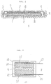
- a lithium secondary cell C which includes a negative electrode 1 having a mesh 2 of a metal, such as nickel, which holds the negative electrode 1 therewith and serves as a current collector.
- a positive electrode 5 is placed in face-to-face relation with the negative electrode 1 through a separator 3 which is impregnated with an electrolyte 4.
- the positive electrode 5 has a mesh 6 of a metal, such as high chromium stainless steel, which holds the positive electrode suitably and serves as a current collector.
- the negative and positive electrodes 1, 5 and the separator 3 impregnated with the electrolyte 4 are hermetically sealed and encased in a casing.
- a metal cover 7 is caulked with a metal casing 8 through a gasket 9 to complete the hermetic sealing.
- At least one of the electrodes should contain a lithium nitride-metal compound.
- the nitride-metal compound is mixed with a conductive material such as graphite, carbon, metal powders or the like in an amount of up to 20 wt%, preferably 2 to 15 wt%, based on the nitride-metal compound.
- a resin binder such as a fluorine resin, various types of synthetic resins including block copolymers or the like, in an amount of up to 20 wt%, preferably from 2 to 15 wt%, based on the nitride-metal compound, thereby obtaining a composition for the negative electrode.
- composition is applied to the metallic mesh 6 and press molded to obtain the negative electrode 1 having, for example, a disk form.
- the composition should preferably contain the nitride-metal compound in an amount not less than 60 wt%. If desired and preferably in some case, the negative electrode may be made of the nitride-metal compound alone as press molded in the metal mesh 2.
- the positive electrode may be made of active substances for positive electrode ordinarily used in lithium secondary cells.
- active substances may be transition metal oxides such as LiCoO2, LiNiO2, LiMnO2 and the like.
- a conductive material such as fibrous graphite, carbon, metallic powders or the like, along with a resin binder such as a fluorine resin in amounts ordinarily used in the art.
- the resultant composition is applied to a metallic mesh and press molded to obtain a positive electrode as usual.
- the active substance for the positive electrode may be made of a nitride-metal compound, to which a conductive material such as fibrous graphite or metallic powder and a binder resin such as polytetrafluoroethylene are further added, like the negative electrode as set out hereinabove.
- the negative electrode may be made of a metallic lithium foil although the transition metal oxides of lithium as illustrated with respect to the positive electrode may also be used.
- the active substances for both negative and positive electrodes may, respectively, contain a nitride-metal compound of the type mentioned hereinbefore.
- the same or difference nitride-metal compounds may be used for both electrodes.
- the nitride-metal compound in the form of a powder may be supported with a metallic mesh merely by press molding as set out hereinabove.
- the separator 3 may be made of finely porous films or membranes which are made, for example, of thermoplastic resins such as polypropylene, polyethylene and the like and glass.
- the separator may have a thickness of 5 to 200 ⁇ m.
- the electrolyte 4 impregnated in the separator 3 is not critical and may be ones which are ordinarily used for this purpose provided that lithium ions are releasable for ionic conduction.
- the electrolyte include lithium phosphorus hexafluoride (LiPF6) dissolved in solvents such as propylene carbonate, dimethoxyethane, ⁇ -butyrolactone, ethylene carbonate, tetrahydrofuran and mixtures thereof.
- solvents such as propylene carbonate, dimethoxyethane, ⁇ -butyrolactone, ethylene carbonate, tetrahydrofuran and mixtures thereof.
- LiPF6 lithium phosphorus hexafluoride
- the solute is usually present in the electrolyte in an amount of 0.5 to 3 moles per liter of the solvent
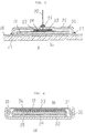
- Fig 2 schematically shows, in section, a solid state lithium secondary cell C1 which includes a positive electrode 10, a solid electrolyte layer 11 and a negative electrode 12 arranged as shown in the figure.
- the positive and negative electrodes 10, 11 are, respectively, attached with lead terminals 13, 14 by use of a carbon paste 15 to provide a cell unit U.
- the cell unit U is sealed and entirely covered with a cured thermosetting resin such as an epoxy resin.
- the positive and negative electrodes may be arranged in a manner similar to those electrodes set out with respect to Fig. 1. More particularly, either or both of the electrodes should be, respectively, made of a lithium nitride-metal compound.
- a solid electrolyte used in the solid electrolyte layer may be added to a positive electrode material up to 75 wt% of the electrode material, by which affinity for the electrolyte layer is improved. By the presence of the solid electrolyte in the positive electrode, smooth passage of an electric current through ionic conduction is ensured in the positive electrode.
- the active substances for the positive and negative electrodes 10, 11 are, respectively, held with a metallic mesh such as by press molding.
- the metallic mesh serves also as a current collector as in Fig. 1.
- the solid electrolyte layer 11 should be a lithium-containing solid electrolyte capable of lithium ion conduction. Specific examples include an amorphous lithium ion conductive compound of the formula, 0.6Li2S-0.4SiS2, 0.6Li2S-0.4P2S6, 0.6Li2S-0.4B2O3, and the like. Besides, lithium-containing polymeric solid electrolytes such as polyethylene oxide-LiClO4, polyethylene oxide-LiCF3SO3 and the like may also be used in the practice of the invention.
- the solid electrolyte layer 11 consists essentially of the solid electrolyte of the type as mentioned above. If necessary, other materials such as fluorine resins, synthetic rubbers and the like binders may be added to the solid electrolyte in amounts up to 20 wt%.
- Fig. 3 schematically shows an electrochemical display device D.
- the device D includes a glass substrate 17 and a transparent electrode 18, such as of indium-tin oxide, formed on the substrate 17 by an electron beam vacuum deposition technique.
- a display electrode layer 19 is further formed on the transparent electrode 18.
- a counter electrode unit U1 is mounted on the electrode layer 19 as shown.
- the electrode unit U1 has a metallic mesh 23 having a counter electrode 24 therein and a light reflecting sheet 25 made of a porous ceramic on which the metallic mesh 23 is mounted.
- the electrode unit U1 is impregnated with a liquid electrolyte 26.
- the electrode unit U1 and the liquid electrolyte 26 are fully covered with a glass casing 22 which is in contact with the transparent electrode 18.
- the glass casing 22 and the transparent electrode 18 are hermetically sealed by means of a UV-cured resin 27.
- the counter electrode unit U1 has a lead terminal 20 vertically extending through an opening (not shown) of the glass casing 22 and fixed with the casing 22 by use of a glass solder 21.
- the display electrode layer 19 is made of a compound such as tungsten oxide, molybdenum oxide, vanadium oxide and the like.
- the counter electrode is made of a lithium nitridoferrate which is able to undergo a topochemical reaction, i.e. intercalation and de-intercalation reactions, by application, for example, of pulse voltages.
- the display electrode is made of a compound which is optically transparent and the counter electrode 24 in the electrode unit U1 is made of a lithium nitride-metal compound with or without a binder resin and a conductive material such as carbon powder as in the foregoing embodiments.
- the electrochemical display device is not specific with respect to the structure thereof except that the counter electrode is made of a lithium nitride-metal compound capable of undergoing the topochemical reaction.
- the porous ceramic sheet 25 is made of alumina, yttria or the like and can be used as a light reflector.
- the electrolyte used may be a solution of a lithium-containing compound such as, for example, LiClO4, LIPF6, LiBF4 or the like, dissolved in a solvent such as propylene carbonate.
- the topochemical reaction cycles continue stably over a long time.
- Fig. 4 schematically shows an electric double-layer capacitor generally indicated as C2.
- the capacitor C2 includes an electrode unit U2 which has a non-polar electrode 28 supported with a metallic mesh, such as a high chromium stainless steel mesh, serving also as a current collector, and a polar electrode 32 supported with a metallic mesh 33, such as a high chromium stainless steel mesh.
- a separator 30 is provided between the non-polar electrode 28 and the polar electrode 32 and is impregnated with a liquid electrolyte 31, thereby completing the electrode unit U2.
- the unit U2 is encased in a casing made, for example, of a stainless steel cover 34 and a stainless steel casing 35 which are combined together as shown and are hermetically sealed with a gasket 36.
- the non-polar electrode 28 is, for example, made of a lithium nitride-metal compound as defined hereinbefore with respect to Fig. 1, along with a binder resin and a conductive material as set forth hereinbefore.
- the polar electrode 32 is made, for example, of a carbon material although any electrochemically inert materials may be used. Such a carbon material is usually mixed with up to 20 wt% of a binder resin such as a fluorine-containing resin, synthetic rubbers or the like.
- the separator may be one which is used in the first embodiment and incudes, for example, a thermoplastic resin fiber sheet.
- the electrolyte used may be one which has been defined in the foregoing embodiments.
- the capacitor is, of course, of the polar type.
- lithium secondary cells With the lithium secondary cell, a great quantity of electricity is passed through the device during the course of working cycles.
- the changes of the end groups set forth hereinbefore greatly influence the performance of the device. Accordingly, the use of lithium nitride-metal compounds as an active substance for the cell device is more effective.
- the quantity of electricity during the working cycles is not so great.
- the working cycle has to be repeated in great number, so that the degradation of its performance is more liable to occur when the end groups suffer changes.
- the use of lithium nitride-metal compounds is effective in suppressing the degradation.
- the present invention is more particularly described by way of examples. Comparative examples are also shown.
- a lithium secondary cell was made using lithium nitridoferrate of the formula, Li3FeN2, as an active substance for negative electrode.
- the lithium nitridoferrate was prepared by mixing lithium nitride (Li3N, commercially available guaranteed reagent) and metallic iron at a molar ratio of 1:1, placing the resultant mixture in an iron crucible, and firing in a nitrogen stream containing a small amount of hydrogen at 900°C for 6 hours to obtain lithium nitridoferrate represented by Li3FeN2.
- the thus obtained lithium nitridoferrate was mixed with 5 wt% of fibrous graphite used as a conductive martial and 1 wt% of a fluorine-containing resin binder thereby providing a negative electrode material for lithium secondary cell.
- 100 mg of the negative electrode material was set or packed in a metallic copper mesh disk with a diameter of 18 mm ⁇ to obtain a negative electrode.
- Lithium cobaltate (LiCoO2) was used as a positive electrode material. Lithium cobaltate was prepared by mixing cobalt oxide and lithium carbonate at a molar ratio of 2:1 and firing in air at 700°C.
- the thus prepared lithium cobaltate was mixed with 5 wt% of fibrous graphite and 1 wt% of a polytetrafluoroethylene binder to provide a positive electrode material. 1000 mg of the positive electrode material was packed in a high chromium stainless steel disk with a diameter of 18 mm ⁇ to obtain a positive electrode.
- An electrolyte used for the cell was a liquid electrolyte which was obtained by dissolving 1 mole of lithium phosphorus hexafluoride (LiPF6) in 1000 ml of a mixed solvent of propylene carbonate (PC) and dimethoxyethane at a ratio by volume of 1:1.
- LiPF6 lithium phosphorus hexafluoride
- PC propylene carbonate
- a separator used was a 50 ⁇ m thick polypropylene finely porous film or sheet.
- a lithium cell of the type shown in Fig. 1 was assembled. More particularly, a negative electrode 1 having a nickel mesh supporting the electrode 1 and serving as a current collector, a separator 3 impregnated with a liquid electrolyte, and a positive electrode 5 having a high chromium stainless steel mesh 6 supporting the positive electrode and serving as a current collector were put one on another, as shown, to provide a cell unit U.
- the unit U was encased in a casing made of a stainless steel cover 7 and a stainless steel case 8. The cover 7 was caulked with the case 8 and hermetically sealed with a gasket 9 to provide a test cell.
- the cell was arranged so that the capacity for the negative electrode was extremely decreased as compared with that of the positive electrode.
- the lithium secondary cell was subjected to a charge and discharge cycle test at a current density of 100 ⁇ A.
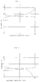
- the charge and discharge curve of the cell is shown in Fig. 5.
- the resultant cell was subjected to a charge and discharge cycle test in the same manner as stated above. As a result, it was found that at the end of the charge of the cell using the graphite as the negative electrode, the charge curve was disturbed, disabling the discharge. We broke up the cell and checked the reason why the cell did not work well, revealing that the electrolyte was extremely reduced in amount and a gas layer was formed on the surface of the negative electrode owing to the generation of the gas accompanied by the charge of the cell.
- the cell for the comparison was preliminarily charged prior to the hermetic sealing, after which the cell was sealed to obtain another test cell.
- This cell was also subjected to a charge and discharge cycle test, revealing that the charge and discharge capacity after 300 cycles was reduced to about 60 % of an initial capacity.
- the cell of the invention does not required any preliminary charging and exhibits good charge and discharge characteristics.
- lithium nitridoferrate was used as an active substance for positive electrode in a lithium secondary cell.
- Lithium nitridoferrate was prepared in the same manner as in Example 1.
- a metallic lithium foil was used as a negative electrode for the cell.
- Example 2 a liquid electrolyte as used in Example 1 was used and a separator used was a 50 ⁇ m thick polypropylene finely porous film.
- Example 1 Using these material, a secondary lithium cell was assembled. In order to assess the characteristics of the lithium nitridoferrate active substance, the cell was so arranged for extreme regulation of positive electrode capacity as in Example 1.
- the cell was subjected to a charge and discharge cycle test in the same manner as in Example 1.
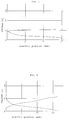
- the charge and discharge curve obtained by the test is shown in Fig. 6.
- the charge and discharge test was continued to 500 cycles, whereupon it was found that any significant variation took place in the charge and discharge curve.
- the invention there could be obtained a lithium secondary cell having good charge and discharge cycles when using lithium nitridoferrate as the active substance for the positive electrode.
- lithium nitridoferrate as used in the foregoing examples was used as an active substance for positive electrode and a lithium ion conductive solid electrolyte was used as a solid electrolyte, thereby providing a solid state lithium secondary cell.
- an amorphous lithium ion conductive solid electrolyte was prepared by mixing Li2S and Si2S at a molar ratio of 3:2 and melting the mixture in a stream of Ar, pouring the resultant melt by pouring into liquid nitrogen to obtain an amorphous lithium ion conductive solid electrolyte of the formula, 0.6Li2S-0.4SiS2.
- a metallic lithium foil was used as a negative electrode.
- a solid state lithium secondary cell having such a construction as shown in Fig. 4 was fabricated.
- a positive electrode 10,. a solid electrolyte layer 11 and a negative electrode 12 were arranged as shown in the figure to provide a cell unit U .
- Lead terminals 13, 14 were, respectively, attached to the positive and negative electrodes 10, 13 and fixed by means of a carbon paste 15.
- the cell U was encased in a cured epoxy resin 16.
- the resultant solid state lithium secondary cell was subjected to a charge and discharge cycle test at a constant current of 100 ⁇ A. As a result, it was found that a significant variation did not take place in the charge and discharge curve up to 300 charge and discharge cycles. Thus, there could be obtained the solid state lithium secondary cell having a good cycle characteristic according to the invention.
- Lithium nitridoferrate was prepared in the same manner as in Example 1.
- the display device was arranged as shown in Fig. 3.
- An indium tin oxide layer 18 was formed as a transparent electrode on a glass substrate 17 by an electron beam vacuum deposition method, on which a tungsten oxide layer 19 was formed as a display electrode according to an EB vapor deposition method.
- a counter electrode unit U1 which was mounted on the display electrode 19.
- the counter electrode unit U1 included a counter electrode 24 which was obtained by mixing 10 mg of lithium nitridoferrate, 5 mg of carbon powder and 2 mg of a polytetrafluoroethylene binder and press molding the mixture along with a stainless steel mesh 23, a porous ceramic sheet 25 used as a light reflector and an electrolyte 26.
- the electrolyte 26 consisted of a solution of 1 mole/liter of LiClO4 in propylene carbonate.
- the unit U1 was sealed in the glass case 22 by use of a UV-cured resin 27.
- the display device was subjected to a color-developing and bleaching cycle test wherein pulse voltages of +2.5 V (20 mseconds) and 0 V (200 mseconds) were applied to the device. As a result, it was found that the device stably worked at least up to 5 x 10⁵ cycles.
- tungsten bronze was prepared by reaction between tungsten oxide (WO3) and n-butyl lithium by immersing tungsten oxide in n-butyl lithium diluted with cyclohexane portion by portion thereby causing Li+ ions to be intercalated into the crystals of the tungsten oxide to obtain tungsten bronze of the formula, LiWO3. Thereafter, the thus obtained tungsten bronze was washed with cyclohexane and dried under reduced pressure to obtain pure tungsten bronze.
- tungsten oxide WO3
- n-butyl lithium diluted with cyclohexane portion by portion thereby causing Li+ ions to be intercalated into the crystals of the tungsten oxide to obtain tungsten bronze of the formula, LiWO3.
- the thus obtained tungsten bronze was washed with cyclohexane and dried under reduced pressure to obtain pure tungsten bronze.
- Example 4 The general procedure of Example 4 was repeated except that tungsten bronze was used in place of lithium nitridoferrate thereby obtaining an electrochemical display device.
- the display device was subjected to a working cycle test in the same manner as set out hereinbefore. As a result, it was found that the color-developing and bleaching did not proceed stably after the 2000th cycle. In order to check the reason why the stable cycles did not proceed, the potential of the single electrode was measured during the course of the working cycles whereupon it was found that the potential of the counter electrode varied as the working cycles proceeded, not permitting the color-developing and bleaching to proceed stably.
- the display device of the invention are better in the working cycle characteristic.
- an electric double-layer capacitor is illustrated using lithium nitridoferrate.
- an electric double-layer capacitor can be broadly classified into two categories including a non-polar capacitor wherein both electrodes are polar in nature and a polar capacitor wherein one of electrodes is polar and the other is non-polar.
- a lithium nitride-metal compound is used as a non-polar electrode to provide a polar electric double-layer capacitor of the invention.
- Lithium nitridoferrate of the formula, Li3FeN2, as prepared and used in Example 1 was provided and mixed with 5 wt% of fibrous graphite and 1 wt% of a fluorine-containing resin binder to provide an electrode material for non-polar electrode.
- the thus obtained material was press rolled in a thickness of 100 ⁇ m, punched into a disk having a diameter of 18 mm ⁇ and pressed in a high chrome stainless steel mesh to provide a disk-shaped non-polar electrode.
- a high surface area carbon material was provided and mixed with 3 wt% of a fluorine-containing resin, followed by rolling to a thickness of 1 mm, punching into a disk having a diameter of 18 mm ⁇ and packing the punched sheet in a high chromium stainless steel mesh to obtain a polar electrode.
- an electric double-layer capacitor having such a structure as shown in Fig. 4 was fabricated in the following manner.
- a non-polar electrode 28 having a high chromium stainless steel mesh therein and a polar electrode 32 having a high chromium stainless steel mesh 33 therein were superposed through a 100 ⁇ m thick separator 30.
- the separator 30 was impregnated with a liquid electrolyte which was composed of 1 mole/liter of LiPF6 in a mixture of propylene carbonate and ethylene carbonate at a ratio by volume of 1:1.
- the resultant cell unit U2 was encased in a stainless steel cover 34 and a stainless steel case 35 which was sealed with a gasket 36 to obtain an electric double-layered capacitor.
- the capacitor was subjected to a constant current charge and discharge cycle test at a constant current of 10 mA and a potential ranging from 0 V to +3 V. As a result, it was found that no variation in charge and discharge curve was observed after 10000 charge and discharge cycles.
- Example 5 For comparison, the general procedure of Example 5 was repeated except that there was used, instead of the non-polar electrode using lithium nitridoferrate, titanium disulfide having a layered structure which had been obtain by immersing titanium disulfide in a solution of n-butyl lithium in cyclohexane thereby permitting lithium ions to be intercalated in the layered structure of titanium disulfide (LiTiS2), thereby obtaining a polar electric double-layered capacitor.
- TiTiS2 titanium disulfide having a layered structure which had been obtain by immersing titanium disulfide in a solution of n-butyl lithium in cyclohexane thereby permitting lithium ions to be intercalated in the layered structure of titanium disulfide (LiTiS2), thereby obtaining a polar electric double-layered capacitor.
- This capacitor was also subjected to a charge and discharge cycle test, whereupon it was found that the charge and discharge curve underwent an appreciable variation after about 4000 cycles.
- a non-polar electric double-layer capacitor was made in the same manner as set out hereinabove except that both electrodes were made of a high surface area carbon material without use of any non-polar electrode.
- the capacitor was subjected to a charge and discharge cycle test. As a consequence, it was found that the capacity was lower than that of the polar electric double-layer capacitor of the example and also that of the polar electric double-layer capacitor for comparison using LiTiS2.
- the electric double-layer capacitor of the invention is better in the working cycle characteristic.
- a lithium secondary cell was made using, as an active substance for negative electrode, lithium nitridoferrate of the formula, Li4FeN2, in place of Li3FeN2 used in Example 1.
- Li4FeN2 was prepared by placing metallic lithium in an iron crucible, and heated and melted in a stream of nitrogen at 900°C, followed by continuation of the heating at 900°C over 5 hours and casting the melt on a water-cooled iron plate to obtain Li4FeN2.
- Example 1 The general procedure of Example 1 was repeated except that Li4FeN2 was used.
- the resultant cell was subjected to a charge and discharge test in the same manner as in Example 1. As a result, it was found that the charge and discharge voltages and capacities, respectively, changed on comparison with the cell of Example 1 and little change was observed in the charge and discharge curve up to 500 charge and discharge cycles. Thus, a good secondary cell was obtained.
- Example 2 The general procedure of Example 2 was repeated except that lithium nitridocobaltate of the formula, Li2CoN, was used as an active substance for positive electrode, thereby obtaining a lithium secondary cell.
- the cell was subjected to a charge and discharge cycle test in the same manner as in Example 2.
- the charge and discharge curve is shown in Fig. 7.
- the charge and discharge voltages and capacities changed on comparison with the cell of Example 2 and little appreciable variation was found in the charge and discharge curve up to 500 charge and discharge cycles. Thus, the cell had a good charge and discharge cycle characteristic.
- These compounds were prepared by mixing metallic lithium and metallic cobalt at a molar ratio of 2+x:1-x and heated in a stream of nitrogen.
- the cells were, respectively, subjected to a charge and discharge cycle test in the same manner as in Example 2.
- Example 2 The general procedure of Example 2 was repeated except that lithium nitridocuprate of the formula, Li2CuN, was used as an active substance for positive electrode, thereby obtaining a lithium secondary cell.
- the cell was subjected to a charge and discharge test in the same manner as in Example 2.
- Fig. 10 The charge and discharge curve is shown in Fig. 10. As will be apparent from Fig. 10, the charge and discharge voltages and capacities changed when compared with those of the cell of Example 2. When the cycle test was continued up to 500 cycles, any appreciable change was not found in the charge and discharge curve. Thus, the cell of the invention had a good charge and discharge cycle characteristic.
- Example 2 The general procedure of Example 2 was repeated except that lithium nitridomanganate of the formula, Li3MnN2, was used as an active substance for positive electrode, thereby obtaining a lithium secondary cell.
- lithium nitridomanganate of the formula, Li3MnN2 was used as an active substance for positive electrode, thereby obtaining a lithium secondary cell.
- the cell was subjected to a charge and discharge test in the same manner as in Example 2.
- the charge and discharge curve is shown in Fig. 11. As will be apparent from Fig. 11, the charge and discharge voltages and capacities changed when compared with those of the cell of Example 2. When the cycle test was continued up to 500 cycles, any appreciable change was not found in the charge and discharge curve. Thus, the cell of the invention had a good charge and discharge cycle characteristic.
- Example 2 The general procedure of Example 2 was repeated except that lithium nitridomanganate of the formula, Li5MnN3, was used as an active substance for positive electrode, thereby obtaining a lithium secondary cell.
- lithium nitridomanganate of the formula, Li5MnN3 was used as an active substance for positive electrode, thereby obtaining a lithium secondary cell.
- the cell was subjected to a charge and discharge test in the same manner as in Example 2.
- the charge and discharge curve is shown in Fig. 12. As will be apparent from Fig. 12, the charge and discharge voltages and capacities changed when compared with those of the cell of Example 2. When the cycle test was continued up to 500 cycles, any appreciable change was not found in the charge and discharge curve. Thus, the cell of the invention had a good charge and discharge cycle characteristic.
- Example 2 The general procedure of Example 2 was repeated except that lithium nitridonickelate of the formula, Li2NiN, was used as an active substance for positive electrode, thereby obtaining a lithium secondary cell.
- lithium nitridonickelate of the formula, Li2NiN was used as an active substance for positive electrode, thereby obtaining a lithium secondary cell.
- the cell was subjected to a charge and discharge test in the same manner as in Example 2.
- Example 1 The general procedure of Example 1 was repeated except that a lithium nitride compound of the formula, Li3Sr3Ni4N4, was used as an active substance for negative electrode, thereby obtaining a lithium secondary cell.
- a lithium nitride compound of the formula, Li3Sr3Ni4N4 was used as an active substance for negative electrode, thereby obtaining a lithium secondary cell.
- the cell was subjected to a charge and discharge test in the same manner as in Example 1.
- Example 2 The general procedure of Example 2 was repeated except that lithium nitridomanganate of the formula, Li7MnN4, was used as an active substance for positive electrode, thereby obtaining a lithium secondary cell.
- lithium nitridomanganate of the formula, Li7MnN4 was used as an active substance for positive electrode, thereby obtaining a lithium secondary cell.
- the cell was subjected to a charge and discharge test in the same manner as in Example 2.
- the charge and discharge voltages and capacities changed when compared with those of the cell of Example 2.
- the cycle test was continued up to 500 cycles, any appreciable change was not found in the charge and discharge curve.
- the cell of the invention had a good charge and discharge cycle characteristic.
- Example 2 The general procedure of Example 2 was repeated except that lithium nitridochromate of the formula, Li6CrN4, was used as an active substance for positive electrode, thereby obtaining a lithium secondary cell.
- lithium nitridochromate of the formula, Li6CrN4 was used as an active substance for positive electrode, thereby obtaining a lithium secondary cell.
- the cell was subjected to a charge and discharge test in the same manner as in Example 2.
- the charge and discharge voltages and capacities changed when compared with those of the cell of Example 2.
- the cycle test was continued up to 500 cycles, any appreciable change was not found in the charge and discharge curve.
- the cell of the invention had a good charge and discharge cycle characteristic.
- Example 2 The general procedure of Example 2 was repeated except that lithium nitridovanadate of the formula, Li7VN4, was used as an active substance for positive electrode, thereby obtaining a lithium secondary cell.
- the cell was subjected to a charge and discharge test in the same manner as in Example 2.
- the charge and discharge voltages and capacities changed when compared with those of the cell of Example 2.
- the cycle test was continued up to 500 cycles, any appreciable change was not found in the charge and discharge curve.
- the cell of the invention had a good charge and discharge cycle characteristic.
- Example 2 The general procedure of Example 2 was repeated except that lithium nitridomolybdate of the formula, Li6MoN4, was used as an active substance for positive electrode, thereby obtaining a lithium secondary cell.
- lithium nitridomolybdate of the formula, Li6MoN4 was used as an active substance for positive electrode, thereby obtaining a lithium secondary cell.
- the cell was subjected to a charge and discharge test in the same manner as in Example 2.
- the charge and discharge voltages and capacities changed when compared with those of the cell of Example 2.
- the cycle test was continued up to 500 cycles, any appreciable change was not found in the charge and discharge curve.
- the cell of the invention had a good charge and discharge cycle characteristic.
- the metals used to form lithium nitride-metal compounds include Fe, Co, Cu, Mn, Cr, V and Mo. W and Nb are also used for this purpose. Similar results are obtained when using multi-component lithium nitride-transition metal compounds.
- This invention relates to electrochemical devices comprise at least a pair of electrodes and a lithium ion conductive electrolyte provided between the pair of electrodes. At least one of the electrodes comprises a lithium nitride-metal compound having a one-dimensional chain structure. By this, the number of end groups which greatly take part in characteristic degradation of the device can be reduced significantly, ensuring good characteristic properties.
- the devices include lithium secondary cells, electric double-layer capacitors, and electrochemical display devices.
Landscapes
- Engineering & Computer Science (AREA)
- Chemical & Material Sciences (AREA)
- Power Engineering (AREA)
- Electrochemistry (AREA)
- Chemical Kinetics & Catalysis (AREA)
- Microelectronics & Electronic Packaging (AREA)
- Materials Engineering (AREA)
- General Chemical & Material Sciences (AREA)
- Inorganic Chemistry (AREA)
- Manufacturing & Machinery (AREA)
- Secondary Cells (AREA)
- Battery Electrode And Active Subsutance (AREA)
- Electric Double-Layer Capacitors Or The Like (AREA)
Applications Claiming Priority (3)
| Application Number | Priority Date | Filing Date | Title |
|---|---|---|---|
| JP224281/93 | 1993-09-09 | ||
| JP22428193A JP3277631B2 (ja) | 1993-09-09 | 1993-09-09 | 電気化学素子 |
| JP22428193 | 1993-09-09 |
Publications (3)
| Publication Number | Publication Date |
|---|---|
| EP0646977A2 true EP0646977A2 (fr) | 1995-04-05 |
| EP0646977A3 EP0646977A3 (fr) | 1996-05-08 |
| EP0646977B1 EP0646977B1 (fr) | 1999-06-09 |
Family
ID=16811316
Family Applications (1)
| Application Number | Title | Priority Date | Filing Date |
|---|---|---|---|
| EP94114099A Expired - Lifetime EP0646977B1 (fr) | 1993-09-09 | 1994-09-08 | Appareils électrochimiques contenant des composés nitrure lithium-métaux dans au moins une électrode d'un groupe d'électrodes |
Country Status (4)
| Country | Link |
|---|---|
| US (1) | US5589298A (fr) |
| EP (1) | EP0646977B1 (fr) |
| JP (1) | JP3277631B2 (fr) |
| DE (1) | DE69418958T2 (fr) |
Cited By (6)
| Publication number | Priority date | Publication date | Assignee | Title |
|---|---|---|---|---|
| EP0744782A1 (fr) * | 1995-05-24 | 1996-11-27 | Sharp Kabushiki Kaisha | Batterie secondaire non aqueuse |
| EP0752728A3 (fr) * | 1995-07-05 | 1997-01-22 | Nippon Telegraph And Telephone Corporation | Matière active négative utilisée dans les accumulateurs au lithium, sa fabrication et les accumulateurs au lithium incorporant cette matière |
| DE19955280C1 (de) * | 1999-11-17 | 2001-06-28 | Univ Berlin Tech | Kontaktstruktur für ein elektrisch betriebenes II/VI-Halbleiterbauelement und Verfahren zu deren Herstellung |
| EP1034572A4 (fr) * | 1997-10-30 | 2004-08-18 | T J Technologies Inc | Materiau ceramique a base de metal de transition et articles produits a l'aide de celle-ci |
| EP1143547A4 (fr) * | 1999-09-24 | 2006-04-26 | Matsushita Electric Industrial Co Ltd | Pile au lithium |
| FR3001339A1 (fr) * | 2013-01-22 | 2014-07-25 | Renault Sa | Batterie au lithium |
Families Citing this family (12)
| Publication number | Priority date | Publication date | Assignee | Title |
|---|---|---|---|---|
| JP3274016B2 (ja) * | 1994-03-17 | 2002-04-15 | 日本化学工業株式会社 | リチウム二次電池用コバルト酸リチウム系正極活物質の製造方法 |
| JP3396076B2 (ja) * | 1994-03-17 | 2003-04-14 | 日本化学工業株式会社 | リチウム二次電池用コバルト酸リチウム系正極活物質の製造方法 |
| US5888669A (en) * | 1996-03-14 | 1999-03-30 | T/J/ Technologies | Transition metal-based ceramic material and articles fabrication therefrom |
| US6190802B1 (en) | 1998-05-22 | 2001-02-20 | T/J Technologies, Inc. | Transition metal based ceramic material and electrodes fabricated therefrom |
| JP2000228196A (ja) | 1998-11-30 | 2000-08-15 | Matsushita Electric Ind Co Ltd | 非水電解質二次電池 |
| JP2002083597A (ja) * | 2000-06-30 | 2002-03-22 | Matsushita Electric Ind Co Ltd | リチウム二次電池 |
| JP2002117836A (ja) | 2000-08-04 | 2002-04-19 | Matsushita Electric Ind Co Ltd | 非水電解質二次電池用負極およびそれを用いた電池 |
| EP1249881A3 (fr) * | 2001-04-10 | 2005-08-03 | Matsushita Electric Industrial Co., Ltd. | Matière d'électrode négative pour pile secondaire à électrolyte non-aqueux et sa méthode de fabrication |
| US20060166097A1 (en) * | 2005-01-26 | 2006-07-27 | Matsushita Electric Industrial Co.,Ltd. | Thermal battery |
| JP5360871B2 (ja) * | 2008-10-21 | 2013-12-04 | Necエナジーデバイス株式会社 | 非水系電解質リチウムイオン二次電池 |
| JP5272810B2 (ja) * | 2009-03-06 | 2013-08-28 | 株式会社豊田中央研究所 | キャパシタ |
| US10566653B2 (en) * | 2015-08-14 | 2020-02-18 | Samsung Electronics Co., Ltd. | Lithium sulfur nitrogen compound for anode barrier coating or solid electrolyte |
Family Cites Families (5)
| Publication number | Priority date | Publication date | Assignee | Title |
|---|---|---|---|---|
| JPS5691374A (en) * | 1979-12-25 | 1981-07-24 | Citizen Watch Co Ltd | Solid electrolyte battery |
| JPS56103872A (en) * | 1980-01-22 | 1981-08-19 | Citizen Watch Co Ltd | Solid-electrolyte battery |
| JPS58137879A (ja) * | 1982-02-10 | 1983-08-16 | 株式会社デンソー | エレクトロクロミツク表示器 |
| ATE114872T1 (de) * | 1987-03-04 | 1994-12-15 | New Brunswick Telephone Co | Lithium-lithiumnitrid-anode. |
| US4888258A (en) * | 1987-03-04 | 1989-12-19 | The New Brunswick Telephone Company, Limited | Lithium-lithium nitride anode |
-
1993
- 1993-09-09 JP JP22428193A patent/JP3277631B2/ja not_active Expired - Fee Related
-
1994
- 1994-09-08 US US08/302,300 patent/US5589298A/en not_active Expired - Fee Related
- 1994-09-08 EP EP94114099A patent/EP0646977B1/fr not_active Expired - Lifetime
- 1994-09-08 DE DE69418958T patent/DE69418958T2/de not_active Expired - Fee Related
Cited By (9)
| Publication number | Priority date | Publication date | Assignee | Title |
|---|---|---|---|---|
| EP0744782A1 (fr) * | 1995-05-24 | 1996-11-27 | Sharp Kabushiki Kaisha | Batterie secondaire non aqueuse |
| US5702843A (en) * | 1995-05-24 | 1997-12-30 | Sharp Kabushiki Kaisha | Nonaqueous secondary battery |
| EP0752728A3 (fr) * | 1995-07-05 | 1997-01-22 | Nippon Telegraph And Telephone Corporation | Matière active négative utilisée dans les accumulateurs au lithium, sa fabrication et les accumulateurs au lithium incorporant cette matière |
| US5834139A (en) * | 1995-07-05 | 1998-11-10 | Nippon Telegraph And Telephone Corporation | Negative electrode material for use in lithium secondary batteries and lithium secondary batteries incorporating this material |
| EP1034572A4 (fr) * | 1997-10-30 | 2004-08-18 | T J Technologies Inc | Materiau ceramique a base de metal de transition et articles produits a l'aide de celle-ci |
| EP1143547A4 (fr) * | 1999-09-24 | 2006-04-26 | Matsushita Electric Industrial Co Ltd | Pile au lithium |
| DE19955280C1 (de) * | 1999-11-17 | 2001-06-28 | Univ Berlin Tech | Kontaktstruktur für ein elektrisch betriebenes II/VI-Halbleiterbauelement und Verfahren zu deren Herstellung |
| FR3001339A1 (fr) * | 2013-01-22 | 2014-07-25 | Renault Sa | Batterie au lithium |
| WO2014114864A1 (fr) * | 2013-01-22 | 2014-07-31 | Renault S.A.S | Batterie au lithium |
Also Published As
| Publication number | Publication date |
|---|---|
| JP3277631B2 (ja) | 2002-04-22 |
| DE69418958T2 (de) | 2000-03-09 |
| US5589298A (en) | 1996-12-31 |
| EP0646977B1 (fr) | 1999-06-09 |
| JPH0778609A (ja) | 1995-03-20 |
| EP0646977A3 (fr) | 1996-05-08 |
| DE69418958D1 (de) | 1999-07-15 |
Similar Documents
| Publication | Publication Date | Title |
|---|---|---|
| US5589298A (en) | Electrochemical devices comprising lithium nitride-metal compounds in at least one of a pair of electrodes | |
| US5053297A (en) | Nonaqueous electrolyte secondary battery | |
| EP1347524B1 (fr) | Materiau actif d'electrode positive et cellule secondaire d'electrolyte non aqueux | |
| US6800397B2 (en) | Non-aqueous electrolyte secondary battery and process for the preparation thereof | |
| US4803137A (en) | Non-aqueous electrolyte secondary cell | |
| US4980250A (en) | Secondary battery | |
| US4668596A (en) | Negative electrodes for non-aqueous secondary batteries composed on conjugated polymer and alkali metal alloying or inserting material | |
| US5770333A (en) | Nonaqueous secondary battery and negative electrode material therefor | |
| EP1030398B1 (fr) | Electrolyte gélifié et batterie à électrolyte gélifié | |
| US6497980B2 (en) | Organic electrolytic solution and lithium secondary battery adopting the same | |
| EP0567149A1 (fr) | Batterie secondaire nonaqueuse | |
| EP0840389A1 (fr) | Pile électrochimique à métal alcalin ayant une densité d'énergie améliorée | |
| US20100291425A1 (en) | Secondary battery | |
| EP0627780B1 (fr) | Pile secondaire à électrolyte liquide non-aqueux | |
| EP0434776A1 (fr) | Electrodes carbonees pour element accumulateur au lithium | |
| EP0199175B1 (fr) | Electrodes négatives pour batteries secondaires non-aqueuses composées de polymères conjugués et de matériaux formant avec des métaux alcalins des alliages ou des composés d'insertion | |
| EP0867955B1 (fr) | Batterie secondaire à électrolyte non-aqueux | |
| US5437942A (en) | Lithium secondary battery | |
| KR100841136B1 (ko) | 비수전해질 이차전지 | |
| EP0837037B1 (fr) | Oxide de fer et de lithium, procédé pour sa synthése et batterie au lithuim l'utilisant | |
| KR20050000318A (ko) | 부극 재료 및 이를 이용한 전지 | |
| JP3237394B2 (ja) | 電気化学素子 | |
| JP2504428B2 (ja) | 二次電池 | |
| JP3496287B2 (ja) | イオン伝導性高分子化合物を用いた電池 | |
| US5916710A (en) | Sodium cobalt bronze batteries and a method for making same |
Legal Events
| Date | Code | Title | Description |
|---|---|---|---|
| PUAI | Public reference made under article 153(3) epc to a published international application that has entered the european phase |
Free format text: ORIGINAL CODE: 0009012 |
|
| 17P | Request for examination filed |
Effective date: 19940908 |
|
| AK | Designated contracting states |
Kind code of ref document: A2 Designated state(s): DE FR GB |
|
| PUAL | Search report despatched |
Free format text: ORIGINAL CODE: 0009013 |
|
| AK | Designated contracting states |
Kind code of ref document: A3 Designated state(s): DE FR GB |
|
| 17Q | First examination report despatched |
Effective date: 19961111 |
|
| GRAG | Despatch of communication of intention to grant |
Free format text: ORIGINAL CODE: EPIDOS AGRA |
|
| GRAG | Despatch of communication of intention to grant |
Free format text: ORIGINAL CODE: EPIDOS AGRA |
|
| GRAH | Despatch of communication of intention to grant a patent |
Free format text: ORIGINAL CODE: EPIDOS IGRA |
|
| GRAH | Despatch of communication of intention to grant a patent |
Free format text: ORIGINAL CODE: EPIDOS IGRA |
|
| GRAA | (expected) grant |
Free format text: ORIGINAL CODE: 0009210 |
|
| AK | Designated contracting states |
Kind code of ref document: B1 Designated state(s): DE FR GB |
|
| REF | Corresponds to: |
Ref document number: 69418958 Country of ref document: DE Date of ref document: 19990715 |
|
| ET | Fr: translation filed | ||
| PLBE | No opposition filed within time limit |
Free format text: ORIGINAL CODE: 0009261 |
|
| STAA | Information on the status of an ep patent application or granted ep patent |
Free format text: STATUS: NO OPPOSITION FILED WITHIN TIME LIMIT |
|
| 26N | No opposition filed | ||
| REG | Reference to a national code |
Ref country code: GB Ref legal event code: IF02 |
|
| PGFP | Annual fee paid to national office [announced via postgrant information from national office to epo] |
Ref country code: DE Payment date: 20060831 Year of fee payment: 13 |
|
| PGFP | Annual fee paid to national office [announced via postgrant information from national office to epo] |
Ref country code: GB Payment date: 20060906 Year of fee payment: 13 |
|
| PGFP | Annual fee paid to national office [announced via postgrant information from national office to epo] |
Ref country code: FR Payment date: 20060908 Year of fee payment: 13 |
|
| GBPC | Gb: european patent ceased through non-payment of renewal fee |
Effective date: 20070908 |
|
| PG25 | Lapsed in a contracting state [announced via postgrant information from national office to epo] |
Ref country code: DE Free format text: LAPSE BECAUSE OF NON-PAYMENT OF DUE FEES Effective date: 20080401 |
|
| REG | Reference to a national code |
Ref country code: FR Ref legal event code: ST Effective date: 20080531 |
|
| PG25 | Lapsed in a contracting state [announced via postgrant information from national office to epo] |
Ref country code: FR Free format text: LAPSE BECAUSE OF NON-PAYMENT OF DUE FEES Effective date: 20071001 |
|
| PG25 | Lapsed in a contracting state [announced via postgrant information from national office to epo] |
Ref country code: GB Free format text: LAPSE BECAUSE OF NON-PAYMENT OF DUE FEES Effective date: 20070908 |