EP0647009B1 - Appareil rotatif magnétique - Google Patents
Appareil rotatif magnétique Download PDFInfo
- Publication number
- EP0647009B1 EP0647009B1 EP94113904A EP94113904A EP0647009B1 EP 0647009 B1 EP0647009 B1 EP 0647009B1 EP 94113904 A EP94113904 A EP 94113904A EP 94113904 A EP94113904 A EP 94113904A EP 0647009 B1 EP0647009 B1 EP 0647009B1
- Authority
- EP
- European Patent Office
- Prior art keywords
- rotor
- magnetic
- electromagnet
- rotating apparatus
- magnets
- Prior art date
- Legal status (The legal status is an assumption and is not a legal conclusion. Google has not performed a legal analysis and makes no representation as to the accuracy of the status listed.)
- Expired - Lifetime
Links
- 230000002093 peripheral effect Effects 0.000 claims description 19
- 239000000696 magnetic material Substances 0.000 claims description 2
- 238000004804 winding Methods 0.000 description 4
- 230000004048 modification Effects 0.000 description 3
- 238000012986 modification Methods 0.000 description 3
- 238000010586 diagram Methods 0.000 description 2
- 230000006978 adaptation Effects 0.000 description 1
- 238000006243 chemical reaction Methods 0.000 description 1
- 238000010276 construction Methods 0.000 description 1
- 230000000694 effects Effects 0.000 description 1
- 230000005684 electric field Effects 0.000 description 1
- 238000004134 energy conservation Methods 0.000 description 1
- 239000000126 substance Substances 0.000 description 1
Images



Classifications
-
- H—ELECTRICITY
- H02—GENERATION; CONVERSION OR DISTRIBUTION OF ELECTRIC POWER
- H02K—DYNAMO-ELECTRIC MACHINES
- H02K11/00—Structural association of dynamo-electric machines with electric components or with devices for shielding, monitoring or protection
-
- H—ELECTRICITY
- H02—GENERATION; CONVERSION OR DISTRIBUTION OF ELECTRIC POWER
- H02K—DYNAMO-ELECTRIC MACHINES
- H02K29/00—Motors or generators having non-mechanical commutating devices, e.g. discharge tubes or semiconductor devices
- H02K29/06—Motors or generators having non-mechanical commutating devices, e.g. discharge tubes or semiconductor devices with position sensing devices
- H02K29/10—Motors or generators having non-mechanical commutating devices, e.g. discharge tubes or semiconductor devices with position sensing devices using light effect devices
-
- H—ELECTRICITY
- H02—GENERATION; CONVERSION OR DISTRIBUTION OF ELECTRIC POWER
- H02K—DYNAMO-ELECTRIC MACHINES
- H02K25/00—DC interrupter motors or generators
Definitions
- the present invention relates to a magnetic rotating apparatus, and more particularly, to a magnetic rotating apparatus which utilizes repulsive forces produced between a permanent magnet and an electromagnet.
- an armature as a rotor consists of turns of wires, and electric field as a stator consists of a permanent magnet.
- current must be usually supplied to windings of the armature which is rotated.
- heat is generated, which gives rise to the problem that not much driving force is efficiently generated. This, in turn, gives rise to the problem that the magnetic forces cannot be efficiently obtained from the permanent magnet.
- a rotor has permanent magnets on its outer peripheral surface which co-operate with an electro-magnet on the stator.
- a magnetically operated switch also on the stator energises and de-energises the electromagnet in synchronism with the passage of the magnetic poles as the rotor turns.
- the object of the present invention is to provide a magnetic rotating apparatus in which rotational energy can be efficiently obtained from the permanent magnet with a minimum amount electrical energy, and in which rotation control can be carried out relatively easily.
- a magnetic rotating apparatus comprising a rotating shaft; a rotor which is fixed to said rotating shaft and which has disposed thereon permanent magnet means, the permament magnet means being tabular magnets and disposed such that a plurality of magnetic poles of one polarity type are arranged along an outer peripheral surface, and a plurality of magnetic poles of the other polarity type are arranged along the inner peripheral surface; electromagnet means which is disposed facing the rotor for developing a magnetic filed which faces and repels the magnetic field of said rotor; and detecting means for detecting a rotational position of said rotor to allow said electromagnet means to be energised in synchronism with the rotation of the motor; characterized in that: the permanent magnet means is disposed on a part only of the outer peripheral surface of said rotor, there being provided on the other part means made of a non-magnetic material of balance the permanent magnet means for rotation; and each pair of corresponding magnetic poles of one and the other
- the rotor and electromagnet may be provided at a plurality of stacked positions.
- the apparatus may further include a second rotor and a second electromagnet means, the detecting means serving also to allow said second electromagnet means to be energised in synchronism with the rotation of the motor, the magnetic poles of the outer peripheral surface of the first rotor being of the opposite polarity type to that of the magnetic poles of the outer peripheral surface of the second rotor.
- a rotary body which is mounted to the rotating shaft which has a plurality of rod-shaped magnets mounted thereon.
- the detecting means may co-operate with energising means such as to energise the electromagnet as the leading permanent magnet passes the electromagnet.
- the energising means may comprise a relay with a solenoid, a contact, and a DC power source; which may be a charger.
- the magnetic field developed by an electromagnet means and that of a permanent magnet means of a rotor repel each other.
- the magnetic field of the permanent magnet means is flattened by the magnetic fields of other nearby permanent magnets and electromagnet means. Therefore, a torque is produced therebetween to efficiently rotate the rotor. Since the rotor has a high inertial force, when the rotor starts rotating, its speed increases by the inertial force and the turning force.
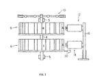
- FIGs. 1 and 2 are schematic diagrams of a magnetic rotating apparatus related to one embodiment of the present invention.
- the term "magnetic rotating apparatus” will include an electric motor, and from its general meaning of obtaining turning force from the magnetic forces of permanent magnets, it will refer to a rotating apparatus utilizing the magnetic forces.
- a rotating shaft 4 is rotatably fixed to a frame 2 with bearings 5.
- a first magnet rotor 6 and a second magnet rotor 8 both of which produce turning forces; and a rotated body 10, which has mounted therealong a plurality of rod-shaped magnets 9 for obtaining the turning forces as energy.
- first and second magnet rotors 6 and 8 there are provided, as will be described later in detail with reference to FIGs. 1 and 2, a first electromagnet 12 and a second electromagnet 14 respectively, which are energized in synchronism with rotations of the first and second magnet rotors 6 and 8, both of which face each other and are each disposed in a magnetic gap.
- the first and second electromagnets 12 and 14 are respectively mounted to a yoke 16, which forms a magnetic path.
- the first and second magnet rotors 6 and 8 each have disposed on its disk-shaped surface a plurality of tabular magnets 22A through 22H for developing a magnetic field for generating the turning forces and balancers 20A through 20H, made of non-magnetic substances, for balancing the magnet rotors 6 and 8.
- the first and second magnet rotors 6 and 8 each have disposed along the disk-shaped surface 24 at equal intervals the eight tabular magnets 22A through 22H along half of the outer peripheral area and the eight balancers 20A through 20H along the other half of the outer peripheral area.
- each of the tabular magnets 22A through 22H is disposed so that its longitudinal axis I makes an angle D with respect to a radial axis line II of the disk-shaped surface 24.
- an angle of 30 degrees and 56 degrees have been confirmed for the angle D.
- An appropriate angle can be set depending on the radius of the disk-shaped surface 24 and the number of tabular magnets 22A through 22H to be disposed on the disk-shaped surface 24. As illustrated in FIG.
- the tabular magnets 22A through 22H on the first magnet rotor 6 are positioned so that their N-poles point outward, while the tabular magnets 22A through 22H on the second magnet rotor 8 are positioned so that their S-poles point outward.
- the first and second electromagnets 12 and 14 are disposed facing the first and second magnet rotors 6 and 8 respectively in the magnetic gap.
- the first and second electromagnets 12 and 14 When the first and second electromagnets 12 and 14 are energized, they develop a magnetic field identical in polarity to the respective tabular magnets 22A through 22H so that they repel one another.
- the first electromagnet 12 is energized so that the side facing the first magnet rotor 6 develops an N-polarity.
- the second electromagnet 14 is energized so that the side facing the tabular magnets 22A through 22H develops a S-polarity.
- the first and second electromagnets 12 and 14, which are magnetically connected by the yoke 16, are magnetized so that the sides facing their respective magnet rotors 6 and 8 are opposite in polarity with respect to each other. This means that the magnetic fields of the electromagnets 12 and 14 can be used efficiently.
- the first and the second magnet rotors 6 and 8 are de-energized when the last tabular magnet 22A has passed.
- an end point Eo is set symmetrical to the starting point So on the rotating disk-shaped surface 24.
- the electromagnet 12 or 14 is de-energized, respectively.
- the magnet rotors 6 and 8 start to rotate when the electromagnets 12 and 14 and their tabular magnets 22A through 22H face one another.
- the contact point of the microswitch is allowed to slide along the surface of the rotating disk-shaped surface 24.
- a step is provided for the starting point So and the end point Eo so that the contact of the microswitch closes between the starting point So and the end point Eo.
- the area along the periphery therebetween protrudes beyond the other peripheral areas of the rotating disk-shaped surface 24. It is apparent that a photo sensor or the like may be used instead of the microswitch as the detector 30 for detecting the rotating position.
- the windings of the electromagnets 12 and 14 are connected to a DC power source 42 through a movable contact of a relay 40, which is connected in series with the windings.
- a series circuit containing the relay 40 (solenoid) and the detector 30 or microswitch is connected to the DC power source 42.
- a charger 44 such as a solar cell is connected to the DC power source 42. It is preferable that the DC power source 42 is constantly chargeable using solar energy or the like.
- a magnetic field distribution shown in FIG. 5 is formed between the tabular magnets 22A through 22H, disposed on each of the magnet rotors 6 and 8, and the electromagnets 12 and 14 which face them, respectively.
- a magnetic field of a tabular magnet of the tabular magnets 22A through 22H, adjacent to the electromagnet 12 or 14 is distorted in the longitudinal direction in correspondence with the rotational direction. This results in the generation of a repulsive force therebetween.
- the repulsive force has a larger component in the longitudinal or perpendicular direction, and produces a torque, as shown by an arrow 32.
- a magnetic field of a tabular magnet of the tabular magnets 22A through 22H, which next enters the magnetic field of the electromagnet 12 or 14, is distorted. Since it moves toward an opposite pole of the preceding tabular magnet of the tabular magnets 22A through 22H, its magnetic field is distorted to a larger extent, and thereby flattened. This means that the repulsive force produced between the tabular magnets of the tabular magnets 22A through 22H, which have already entered the magnetic field of the electromagnets 12 or 14, is larger than the repulsive force developed between the next-entering tabular magnets of the tabular magnets 22A through 22H and the electromagnets 12 or 14.
- a turning force acts upon the rotating disk-shaped surface 24.
- the rotating disk-shaped surface 24 having had turning force imparted thereto, continues to rotate due to inertial forces, even when it has been de-energized after the end point Eo has coincided with the center point Ro of the electromagnet 12 or 14. The larger the inertial force, the smoother the rotation.
- the number of tabular magnets 22A through 22H is not limited to "8" as shown in FIGs. 1 and 3. Any number of magnets may be used.
- the tabular magnets 22A through 22H are disposed along half of the peripheral area of the disk-shaped surface 24, and the balancers 20A through 20H are disposed along the other half of the peripheral area, the tabular magnets may further be disposed along other areas of the disk-shaped surface 24. It is preferable that balancers, in addition to magnets, are provided along a portion of the peripheral area on the disk-shaped surface.
- the counter weights which do not need to be formed into separate blocks, may be formed into one sheet of plate which extends on the outer peripheral area of the disk-shaped surface.
- the circuit may be so constructed as to allow, upon increased number of rotations, energization of the electromagnets for every rotation of the rotating disk-shaped surface, starting from its second rotation onwards.
- a tabular magnet has been used for the permanent magnet, but other types of permanent magnets may also be used.
- any type of magnet may be used as the permanent magnet means as long as a plurality of magnetic poles of one type is disposed along the outer surface of the inner periphery and a plurality of magnetic poles of the other type are disposed along the inner peripheral surface of the disk-shaped surface, so that a pair of corresponding magnetic poles of one and the other polarities is obliquely arranged, with respect to the radial line 11, as shown in FIG. 3.
- the tabular magnets 22A through 22H are mounted on the magnet rotors 6 and 8 in the above embodiment, they may be electromagnets.
- the electromagnets 12 and 14 may be the alternative of electromagnets or permanent magnets.
- rotational energy can be efficiently obtained from permanent magnets. This is made possible by minimizing as much as possible current supplied to the electromagnets, so that only a required amount of electrical energy is supplied to the electromagnets.
Landscapes
- Engineering & Computer Science (AREA)
- Power Engineering (AREA)
- Magnetic Bearings And Hydrostatic Bearings (AREA)
- Permanent Magnet Type Synchronous Machine (AREA)
- Power Steering Mechanism (AREA)
- Dynamo-Electric Clutches, Dynamo-Electric Brakes (AREA)
- Reciprocating, Oscillating Or Vibrating Motors (AREA)
- Mechanical Optical Scanning Systems (AREA)
- Investigating Or Analyzing Materials By The Use Of Magnetic Means (AREA)
- Valve Device For Special Equipments (AREA)
- Liquid Crystal (AREA)
- Valve-Gear Or Valve Arrangements (AREA)
Claims (8)
- Appareil rotatif magnétique comprenant un arbre tournant (4),a) un rotor (6, 8) qui est fixé à cet arbre tournant (4) et sur lequel sont placés des aimants permanents (22A à 22H), ces aimants permanents (22A à 22H) étant des aimants tabulaires et étant disposés de façon qu'une série de pôles magnétiques d'une polarité soient placés le long d'une surface périphérique extérieure et une série de pôles magnétiques de l'autre polarité soient placés le long de la surface périphérique intérieure,b) des moyens électromagnétiques (12, 14) placés en face du rotor (6, 8) pour produire un champ magnétique faisant face au champ magnétique du rotor (6, 8) et repoussant ce champ, etc) un moyen de détection (30) pour la détection de la position angulaire du rotor (6, 8) pour permettre l'alimentation des moyens électromagnétiques en synchronisme avec la rotation du moteur,caractérisé par le fait que :d) les aimants permanents sont placés sur une partie seulement de la surface périphérique extérieure du rotor (6, 8), sur l'autre partie étant prévus des moyens faits d'une matière non magnétique destinés à équilibrer les aimants permanents lors de la rotation, ete) chaque paire de pôles magnétiques correspondants de l'une et de l'autre polarités est placée obliquement par rapport à une ligne radiale.
- Appareil rotatif magnétique selon la revendication 1, dans lequel le rotor et les moyens électromagnétiques sont prévus à une série d'endroits superposés.
- Appareil rotatif magnétique selon la revendication 1, comportant en outre un deuxième rotor également du type défini au paragraphe a) de la revendication 1, des deuxièmes moyens électromagnétiques également du type défini au paragraphe b) de la revendication 1, ce deuxième rotor et ces deuxièmes moyens électromagnétiques étant également disposés de la manière définie aux paragraphes d) et e) de la revendication 1, le moyen de détection (30) servant aussi à permettre l'alimentation des deuxièmes moyens électromagnétiques en synchronisme avec la rotation du moteur, et les pôles magnétiques de la surface périphérique extérieure du premier rotor étant de la polarité opposée à celle des pôles magnétiques de la surface périphérique extérieure du deuxième rotor.
- Appareil rotatif magnétique selon l'une des revendications 1, 2 et 3, comportant en outre un corps tournant qui est monté sur l'arbre tournant et sur lequel sont montés une série d'aimants en forme de tige.
- Appareil rotatif magnétique selon l'une des revendications précédentes, dans lequel les aimants permanents sont remplacés par des électro-aimants et les électro-aimants sont remplacés par des aimants permanents.
- Appareil rotatif magnétique selon l'une des revendications précédentes, dans lequel le moyen de détection coopère avec un moyen d'alimentation de façon à alimenter l'électroaimant lorsque l'aimant permanent de tête passe devant celui-ci.
- Appareil rotatif magnétique selon la revendication 6, dans lequel le moyen d'alimentation comprend un relais ayant un solénoïde et un contact, et une source d'énergie en courant continu.
- Appareil rotatif magnétique selon la revendication 7, dans lequel la source d'énergie en courant continu est reliée électriquement à un chargeur.
Applications Claiming Priority (2)
| Application Number | Priority Date | Filing Date | Title |
|---|---|---|---|
| JP230162/93 | 1993-09-16 | ||
| JP5230162A JP2968918B2 (ja) | 1993-09-16 | 1993-09-16 | 磁力回転装置 |
Publications (2)
| Publication Number | Publication Date |
|---|---|
| EP0647009A1 EP0647009A1 (fr) | 1995-04-05 |
| EP0647009B1 true EP0647009B1 (fr) | 1997-12-10 |
Family
ID=16903575
Family Applications (1)
| Application Number | Title | Priority Date | Filing Date |
|---|---|---|---|
| EP94113904A Expired - Lifetime EP0647009B1 (fr) | 1993-09-16 | 1994-09-05 | Appareil rotatif magnétique |
Country Status (24)
| Country | Link |
|---|---|
| US (1) | US5594289A (fr) |
| EP (1) | EP0647009B1 (fr) |
| JP (1) | JP2968918B2 (fr) |
| KR (1) | KR100225263B1 (fr) |
| CN (1) | CN1037050C (fr) |
| AT (1) | ATE161128T1 (fr) |
| AU (1) | AU677854B2 (fr) |
| BG (1) | BG61589B1 (fr) |
| BR (1) | BR9403471A (fr) |
| CA (1) | CA2131336C (fr) |
| DE (1) | DE69407250T2 (fr) |
| DK (1) | DK0647009T3 (fr) |
| ES (1) | ES2114639T3 (fr) |
| FI (1) | FI116104B (fr) |
| GR (1) | GR3026264T3 (fr) |
| HU (1) | HU220522B1 (fr) |
| IL (1) | IL110879A (fr) |
| MY (1) | MY111454A (fr) |
| NO (1) | NO305497B1 (fr) |
| NZ (1) | NZ264373A (fr) |
| PL (1) | PL176647B1 (fr) |
| RU (1) | RU2128872C1 (fr) |
| SK (1) | SK282184B6 (fr) |
| TW (1) | TW303542B (fr) |
Cited By (3)
| Publication number | Priority date | Publication date | Assignee | Title |
|---|---|---|---|---|
| RU2266606C2 (ru) * | 2003-03-20 | 2005-12-20 | Реднов Федор Александрович | Электрическая машина |
| RU2290745C1 (ru) * | 2005-04-13 | 2006-12-27 | Открытое акционерное общество "Акционерная компания по транспорту нефти "ТРАНСНЕФТЬ" | Устройство управления электроприводом запорной арматуры |
| RU2314450C1 (ru) * | 2006-05-18 | 2008-01-10 | Открытое акционерное общество "Акционерная компания по транспорту нефти "ТРАНСНЕФТЬ" | Устройство управления электроприводом запорной арматуры |
Families Citing this family (82)
| Publication number | Priority date | Publication date | Assignee | Title |
|---|---|---|---|---|
| JP3713327B2 (ja) * | 1996-04-11 | 2005-11-09 | 弘平 湊 | 磁力回転装置 |
| JP3403690B2 (ja) * | 2000-03-02 | 2003-05-06 | 株式会社日立製作所 | 永久磁石式回転電機を用いたハイブリット電気自動車 |
| JP4145660B2 (ja) * | 2001-03-14 | 2008-09-03 | 明 保坂 | 磁気モータ |
| US6759775B2 (en) * | 2002-02-13 | 2004-07-06 | Abacat, Inc. | Permanent magnet actuating mechanism |
| US20050140231A1 (en) * | 2002-05-01 | 2005-06-30 | Makoto Ogoshi | Power generator and torque amplifier |
| US20040100099A1 (en) * | 2002-11-27 | 2004-05-27 | Eaton Peter T | Magnetic field power converter |
| US7268454B2 (en) | 2003-01-17 | 2007-09-11 | Magnetic Torque International, Ltd. | Power generating systems |
| US7233088B2 (en) | 2003-01-17 | 2007-06-19 | Magnetic Torque International, Ltd. | Torque converter and system using the same |
| EA007416B1 (ru) * | 2003-01-17 | 2006-10-27 | Магнетик Торк Интернэшнл, Лтд. | Преобразователь крутящего момента и система, использующая преобразователь крутящего момента |
| WO2004088817A2 (fr) * | 2003-03-28 | 2004-10-14 | John Bates | Moteur magnetique a efficacite amelioree |
| JP4614641B2 (ja) * | 2003-08-26 | 2011-01-19 | 延江 湊 | 運動量増大装置 |
| JP4536339B2 (ja) * | 2003-08-26 | 2010-09-01 | 延江 湊 | 直接駆動式磁力回転装置 |
| JP2005245079A (ja) * | 2004-02-25 | 2005-09-08 | Kohei Minato | 磁力回転式モータ発電機 |
| US8084904B2 (en) * | 2004-06-30 | 2011-12-27 | Future Force, Llc | Magnetic propulsion motor |
| US20060033392A1 (en) * | 2004-08-12 | 2006-02-16 | Ritchey Jonathan G | Polyphasic multi-coil generator |
| US7081696B2 (en) * | 2004-08-12 | 2006-07-25 | Exro Technologies Inc. | Polyphasic multi-coil generator |
| ES2281221B1 (es) * | 2004-09-07 | 2008-08-16 | Ramon Freixas Vila | Dispositivo magnetico rotatorio. |
| US7191861B2 (en) * | 2004-09-28 | 2007-03-20 | Phuong Bui | Electromagnet propelled wheeled vehicle |
| US20060087187A1 (en) * | 2004-10-27 | 2006-04-27 | Magnetic Torque International, Ltd. | Multivariable generator and method of using the same |
| US7808142B2 (en) * | 2004-10-27 | 2010-10-05 | E3 Solutions, Llc | Multivariable generator and method of using the same |
| US20060111191A1 (en) * | 2004-11-19 | 2006-05-25 | Magnetic Torque International | Torque transfer system and method of using the same |
| US7233087B2 (en) * | 2005-01-31 | 2007-06-19 | Watson Charles S | Electromagnetically driven rotary motor |
| CA2603839C (fr) * | 2005-04-04 | 2013-07-09 | Yoko Kinoshita | Mecanisme rotatif |
| US7151332B2 (en) * | 2005-04-27 | 2006-12-19 | Stephen Kundel | Motor having reciprocating and rotating permanent magnets |
| US20070296284A1 (en) * | 2005-10-12 | 2007-12-27 | Victor Diduck | Magnetic Motor |
| ES2281300B1 (es) * | 2006-04-04 | 2009-04-01 | Ramon Freixas Vila | Motor magnetico. |
| CN102647058A (zh) | 2006-06-08 | 2012-08-22 | Exro技术公司 | 电力设备 |
| JP2008104324A (ja) * | 2006-09-19 | 2008-05-01 | Sumitomo Electric Ind Ltd | 駆動装置 |
| US20100213778A1 (en) * | 2009-02-24 | 2010-08-26 | Knutson Roger C | Magnetic Motor With Associated Alternator |
| KR101021126B1 (ko) | 2009-04-20 | 2011-03-14 | 삼성전기주식회사 | 모터 |
| US20110304232A1 (en) * | 2009-05-29 | 2011-12-15 | Garland Rush | Electromagnetically driven motor and electric power generator |
| DE102009031205A1 (de) | 2009-07-01 | 2011-01-05 | Reinhold Johannes Gorzellik | Antriebsmaschine mit elektrischer, magnetischer und mechanischer Energie als Input |
| US20110001381A1 (en) * | 2009-07-06 | 2011-01-06 | Mcdaniel Scott L | McDaniel magnet motor |
| DE102009034343A1 (de) | 2009-07-23 | 2011-02-03 | Reinhold Johannes Gorzellik | Antriebsmaschine mit elektrischer, magnetischer und mechanischer Energie als Input |
| US8390162B2 (en) * | 2009-10-30 | 2013-03-05 | Louis J. Finkle | Reconfigurable inductive to synchronous motor |
| US8288908B2 (en) * | 2009-10-30 | 2012-10-16 | Finkle Louis J | Reconfigurable inductive to synchronous motor |
| US8952587B2 (en) | 2009-10-30 | 2015-02-10 | Louis J. Finkle | Windmill generator with mechanically tuneable permanent magnetic field |
| US8072108B2 (en) * | 2009-10-30 | 2011-12-06 | Finkle Louis J | Electric motor or generator with mechanically tuneable permanent magnetic field |
| US8097993B2 (en) * | 2009-10-30 | 2012-01-17 | Finkle Louis J | Electric motor and/or generator with mechanically tuneable permanent magnetic field |
| JP5297398B2 (ja) * | 2010-01-26 | 2013-09-25 | 株式会社日立製作所 | 全閉型電動機 |
| US20110095544A1 (en) * | 2010-07-21 | 2011-04-28 | Arkadiusz Fijalkowski | Magnetic Drive Inducing Constant-Speed Rotation |
| RU2470442C2 (ru) * | 2010-09-27 | 2012-12-20 | Вячеслав Викторович Кияшко | Электромагнитный двигатель |
| WO2012137909A1 (fr) * | 2011-04-06 | 2012-10-11 | 尾崎 一枝 | Mécanisme d'entraînement utilisant un aimant permanent |
| US8981608B2 (en) * | 2011-04-21 | 2015-03-17 | Harold Ariel | Method of propulsion |
| JP2013055789A (ja) * | 2011-09-02 | 2013-03-21 | Yoshihide Ueda | 電動発電機 |
| US9991774B2 (en) | 2011-09-26 | 2018-06-05 | Dennis R. Kuntz | DC field gradient motor |
| KR101281336B1 (ko) * | 2011-12-27 | 2013-07-03 | 주식회사 포스코 | 복합 마그네트를 이용한 주행장치 |
| US8487484B1 (en) * | 2012-03-15 | 2013-07-16 | Torque Multipliers, LLC | Permanent magnet drive apparatus and operational method |
| US9250017B2 (en) | 2012-03-16 | 2016-02-02 | Jerry D. Miller | Magnet supported rotary drum dryer |
| US10284029B2 (en) | 2012-03-20 | 2019-05-07 | Linear Labs, LLC | Brushed electric motor/generator |
| EP2828962B1 (fr) | 2012-03-20 | 2021-05-12 | Linear Labs, Inc. | Moteur électrique/générateur cc amélioré ayant des densités de flux à aimant permanent supérieures |
| US10263480B2 (en) | 2012-03-20 | 2019-04-16 | Linear Labs, LLC | Brushless electric motor/generator |
| US9729016B1 (en) | 2012-03-20 | 2017-08-08 | Linear Labs, Inc. | Multi-tunnel electric motor/generator |
| US9419504B2 (en) | 2012-04-20 | 2016-08-16 | Louis J. Finkle | Hybrid induction motor with self aligning permanent magnet inner rotor |
| US9484794B2 (en) | 2012-04-20 | 2016-11-01 | Louis J. Finkle | Hybrid induction motor with self aligning permanent magnet inner rotor |
| US9371856B2 (en) | 2012-08-03 | 2016-06-21 | Stephen Kundel | Non-contact thrust bearing using permanent magnets |
| US9923440B2 (en) | 2014-01-09 | 2018-03-20 | Motor Generator Technology, Inc. | Hybrid electric motor with self aligning permanent magnet and squirrel cage rotors |
| US10476363B2 (en) | 2014-01-09 | 2019-11-12 | Louis J. Finkle | Hybrid electric motor with self aligning permanent magnet and squirrel cage dual rotors magnetically coupled with permeant magnets and bars at synchronous speed |
| US9923439B2 (en) | 2014-01-09 | 2018-03-20 | Motor Generator Technology, Inc. | Hybrid electric motor with self aligning permanent magnet and squirrel cage rotors |
| US10998802B2 (en) | 2017-02-21 | 2021-05-04 | Louis J. Finkle | Hybrid induction motor with self aligning hybrid induction/permanent magnet rotor |
| KR101584509B1 (ko) * | 2014-11-17 | 2016-01-15 | 석세명 | 자력회전 가속장치 및 이를 포함하는 발전 시스템 |
| JP5792411B1 (ja) * | 2015-05-22 | 2015-10-14 | 康▲広▼ 小松 | 磁力回転装置 |
| US10447103B2 (en) | 2015-06-28 | 2019-10-15 | Linear Labs, LLC | Multi-tunnel electric motor/generator |
| US10476362B2 (en) | 2015-06-28 | 2019-11-12 | Linear Labs, LLC | Multi-tunnel electric motor/generator segment |
| CA3004702A1 (fr) | 2015-10-20 | 2017-04-27 | Linear Labs, LLC | Machine electrique a flux circonferentiel a mecanismes d'affaiblissement de champ et son procede d'utilisation |
| DE202016004158U1 (de) | 2016-07-02 | 2016-07-25 | Rudolf Fink | Magnetmotor |
| DE102016008163A1 (de) | 2016-07-02 | 2018-01-04 | Rudolf Fink | Magnetmotor |
| CA3034629A1 (fr) | 2016-09-05 | 2018-03-08 | Linear Labs, LLC | Moteur/generateur electrique multi-tunnel ameliore |
| WO2018213919A1 (fr) | 2017-05-23 | 2018-11-29 | Dpm Technologies Inc. | Appareil, procédé et système témoin de configuration d'une bobine variable |
| EP3425781B1 (fr) | 2017-07-08 | 2024-06-19 | Agnieszka Ocwieja | Moteur utilisant des aimants permanents avec stator mobile commandé par des actionneurs linéaires |
| CN108158181A (zh) * | 2018-03-20 | 2018-06-15 | 张丽 | 一种便利发圈 |
| US20210249981A1 (en) | 2018-09-05 | 2021-08-12 | Dpm Technologies Inc. | Systems and methods for intelligent control of rotating electric machines |
| EA202190687A1 (ru) | 2018-09-20 | 2021-07-05 | ФААНИКС ПиТиВай ЛТД | Генерирование энергии |
| JP6616538B1 (ja) | 2019-02-12 | 2019-12-04 | 株式会社シンプル東京 | 回転装置及び発電システム |
| US11722026B2 (en) | 2019-04-23 | 2023-08-08 | Dpm Technologies Inc. | Fault tolerant rotating electric machine |
| US11277062B2 (en) | 2019-08-19 | 2022-03-15 | Linear Labs, Inc. | System and method for an electric motor/generator with a multi-layer stator/rotor assembly |
| US11522436B2 (en) | 2019-10-15 | 2022-12-06 | Darrell Schmidt Enterprises, Inc. | Permanently magnetized enhanced generator |
| US11296588B2 (en) | 2019-10-15 | 2022-04-05 | Darrell Schmidt Enterprises, Inc. | Magnetic coupler |
| US11897362B2 (en) | 2021-05-04 | 2024-02-13 | Exro Technologies Inc. | Systems and methods for individual control of a plurality of controllable units of battery cells |
| CN117337545A (zh) | 2021-05-13 | 2024-01-02 | Exro技术公司 | 驱动多相电机的线圈的方法及装置 |
| US11626774B1 (en) | 2022-04-07 | 2023-04-11 | Chad Gray-Cingcade | Energy generation system and method using electromagnets |
| US12031527B1 (en) * | 2023-01-18 | 2024-07-09 | Bold Earth Scientific, LLC | Mechanical system to amplify work output to be greater than work input |
Family Cites Families (16)
| Publication number | Priority date | Publication date | Assignee | Title |
|---|---|---|---|---|
| US2919358A (en) * | 1955-03-23 | 1959-12-29 | Bell Telephone Labor Inc | Apparatus for converting radiant energy to electromechanical energy |
| JPS56136165A (en) * | 1980-03-25 | 1981-10-24 | Kouji Shiroie | Rotary machine applying permanent magnet |
| US4629921A (en) * | 1982-09-14 | 1986-12-16 | Gavaletz John S | Dynamoelectric machine rotor |
| FR2568067A1 (fr) * | 1984-03-16 | 1986-01-24 | Lecat Jacky | Moteur magnetique autonome a aimants permanents |
| JPS61277365A (ja) * | 1985-05-30 | 1986-12-08 | Yoshimatsu Wakabayashi | 永久磁石による回転機 |
| US4642534A (en) * | 1985-07-15 | 1987-02-10 | Emile Mitchell | Magnetic driven motor |
| JPS62171476A (ja) * | 1986-01-23 | 1987-07-28 | Kiyoyoshi Hamada | 電気不用モ−タ− |
| JPS62171458A (ja) * | 1986-01-24 | 1987-07-28 | Kohei Minato | 磁力回転装置 |
| WO1988005976A1 (fr) * | 1987-02-04 | 1988-08-11 | Franklin's Magnetic Generator Corp. | Machine dynamomagnetique |
| SE464245B (sv) * | 1987-07-13 | 1991-03-25 | Pronova Ab | Foerpackningsband |
| JPS6469275A (en) * | 1987-09-07 | 1989-03-15 | Masami Ono | Magnetic force neutralizing permanent magnet rotating device |
| JPH01170361A (ja) * | 1987-12-24 | 1989-07-05 | Atlas Yoko:Kk | 永久磁石利用の動力機 |
| US5113272A (en) * | 1990-02-12 | 1992-05-12 | Raychem Corporation | Three dimensional semiconductor display using liquid crystal |
| WO1992022958A1 (fr) * | 1991-06-18 | 1992-12-23 | Vakugo Pty. Limited | Turbine a aimants permanents |
| US5258735A (en) * | 1991-10-28 | 1993-11-02 | Allwine Jr Elmer C | Multi-pole composite magnet used in a magnetic encoder |
| EP0551533A1 (fr) * | 1992-01-13 | 1993-07-21 | Forschungsgesellschaft Magnetfeld Energie (Fme) | Convertisseur d'énergie de champ magnétique pour utiliser comme moteur ou générateur |
-
1993
- 1993-09-16 JP JP5230162A patent/JP2968918B2/ja not_active Expired - Lifetime
-
1994
- 1994-08-30 MY MYPI94002271A patent/MY111454A/en unknown
- 1994-09-01 CA CA002131336A patent/CA2131336C/fr not_active Expired - Fee Related
- 1994-09-02 NZ NZ264373A patent/NZ264373A/en unknown
- 1994-09-05 AT AT94113904T patent/ATE161128T1/de not_active IP Right Cessation
- 1994-09-05 ES ES94113904T patent/ES2114639T3/es not_active Expired - Lifetime
- 1994-09-05 NO NO943277A patent/NO305497B1/no unknown
- 1994-09-05 DE DE69407250T patent/DE69407250T2/de not_active Expired - Fee Related
- 1994-09-05 DK DK94113904T patent/DK0647009T3/da active
- 1994-09-05 EP EP94113904A patent/EP0647009B1/fr not_active Expired - Lifetime
- 1994-09-05 IL IL110879A patent/IL110879A/xx active IP Right Revival
- 1994-09-07 KR KR1019940022441A patent/KR100225263B1/ko not_active Expired - Fee Related
- 1994-09-08 BR BR9403471A patent/BR9403471A/pt not_active IP Right Cessation
- 1994-09-13 HU HU9402621A patent/HU220522B1/hu not_active IP Right Cessation
- 1994-09-14 TW TW083108501A patent/TW303542B/zh not_active IP Right Cessation
- 1994-09-14 FI FI944260A patent/FI116104B/fi active IP Right Grant
- 1994-09-14 SK SK1108-94A patent/SK282184B6/sk unknown
- 1994-09-15 AU AU73014/94A patent/AU677854B2/en not_active Ceased
- 1994-09-15 BG BG99044A patent/BG61589B1/bg unknown
- 1994-09-15 RU RU94033095A patent/RU2128872C1/ru not_active IP Right Cessation
- 1994-09-16 PL PL94305068A patent/PL176647B1/pl not_active IP Right Cessation
- 1994-09-16 CN CN94115388A patent/CN1037050C/zh not_active Expired - Lifetime
-
1995
- 1995-12-14 US US08/574,582 patent/US5594289A/en not_active Expired - Lifetime
-
1998
- 1998-02-27 GR GR980400442T patent/GR3026264T3/el unknown
Cited By (3)
| Publication number | Priority date | Publication date | Assignee | Title |
|---|---|---|---|---|
| RU2266606C2 (ru) * | 2003-03-20 | 2005-12-20 | Реднов Федор Александрович | Электрическая машина |
| RU2290745C1 (ru) * | 2005-04-13 | 2006-12-27 | Открытое акционерное общество "Акционерная компания по транспорту нефти "ТРАНСНЕФТЬ" | Устройство управления электроприводом запорной арматуры |
| RU2314450C1 (ru) * | 2006-05-18 | 2008-01-10 | Открытое акционерное общество "Акционерная компания по транспорту нефти "ТРАНСНЕФТЬ" | Устройство управления электроприводом запорной арматуры |
Also Published As
Similar Documents
| Publication | Publication Date | Title |
|---|---|---|
| EP0647009B1 (fr) | Appareil rotatif magnétique | |
| KR101140833B1 (ko) | 자력 회전식 모터 | |
| EP0071629B1 (fr) | Moteur ou generateur a courant continu du type a disque, sans balai | |
| US4306164A (en) | Pulse motor | |
| US5233251A (en) | Electric motor with non-radial magnetic drive system | |
| US20080224550A1 (en) | Magnetic Motor | |
| KR101011201B1 (ko) | 전자석 모터를 이용한 전동장치 | |
| JPH1198794A (ja) | トルク発生装置 | |
| US6469412B1 (en) | Universal electric motor with variable air gap | |
| JP3302283B2 (ja) | 回転電機およびその回転電機を用いた発電機並びに電動機 | |
| EP0164742B1 (fr) | Moteur sans balai | |
| HK1001848B (en) | Magnetic rotating apparatus | |
| JPS63190543A (ja) | インナ−ロ−タ型dcブラシレスモ−タ | |
| CZ9402269A3 (cs) | Elektrický rotační motor | |
| JPS63190544A (ja) | アウタ−ロ−タ型dcブラシレスモ−タ | |
| JPWO2002035683A1 (ja) | 磁束閉じ込め可能なロータを備えた電動機 | |
| JPH0456543B2 (fr) | ||
| JPH0417557A (ja) | 有鉄心形単相ブラシレスモータ | |
| GB2111760A (en) | Motor | |
| JPH01114355A (ja) | リラクタンスモータ | |
| JP2000152602A (ja) | 電磁回転機 | |
| JPH0549227A (ja) | ステツピング電磁アクチユエータ | |
| HK1019269A (en) | Motive power generating apparatus utilizing energy of permanent magnet |
Legal Events
| Date | Code | Title | Description |
|---|---|---|---|
| PUAI | Public reference made under article 153(3) epc to a published international application that has entered the european phase |
Free format text: ORIGINAL CODE: 0009012 |
|
| AK | Designated contracting states |
Kind code of ref document: A1 Designated state(s): AT BE CH DE DK ES FR GB GR IE IT LI LU NL PT SE |
|
| 17P | Request for examination filed |
Effective date: 19950919 |
|
| 17Q | First examination report despatched |
Effective date: 19960628 |
|
| GRAG | Despatch of communication of intention to grant |
Free format text: ORIGINAL CODE: EPIDOS AGRA |
|
| GRAH | Despatch of communication of intention to grant a patent |
Free format text: ORIGINAL CODE: EPIDOS IGRA |
|
| GRAH | Despatch of communication of intention to grant a patent |
Free format text: ORIGINAL CODE: EPIDOS IGRA |
|
| GRAA | (expected) grant |
Free format text: ORIGINAL CODE: 0009210 |
|
| AK | Designated contracting states |
Kind code of ref document: B1 Designated state(s): AT BE CH DE DK ES FR GB GR IE IT LI LU NL PT SE |
|
| REF | Corresponds to: |
Ref document number: 161128 Country of ref document: AT Date of ref document: 19971215 Kind code of ref document: T |
|
| REG | Reference to a national code |
Ref country code: CH Ref legal event code: EP |
|
| REF | Corresponds to: |
Ref document number: 69407250 Country of ref document: DE Date of ref document: 19980122 |
|
| ET | Fr: translation filed | ||
| REG | Reference to a national code |
Ref country code: CH Ref legal event code: NV Representative=s name: E. BLUM & CO. PATENTANWAELTE |
|
| ITF | It: translation for a ep patent filed | ||
| REG | Reference to a national code |
Ref country code: IE Ref legal event code: FG4D Free format text: 77819 |
|
| REG | Reference to a national code |
Ref country code: ES Ref legal event code: FG2A Ref document number: 2114639 Country of ref document: ES Kind code of ref document: T3 |
|
| REG | Reference to a national code |
Ref country code: PT Ref legal event code: SC4A Free format text: AVAILABILITY OF NATIONAL TRANSLATION Effective date: 19980310 |
|
| REG | Reference to a national code |
Ref country code: DK Ref legal event code: T3 |
|
| PLBE | No opposition filed within time limit |
Free format text: ORIGINAL CODE: 0009261 |
|
| STAA | Information on the status of an ep patent application or granted ep patent |
Free format text: STATUS: NO OPPOSITION FILED WITHIN TIME LIMIT |
|
| 26N | No opposition filed | ||
| REG | Reference to a national code |
Ref country code: GB Ref legal event code: IF02 |
|
| PGFP | Annual fee paid to national office [announced via postgrant information from national office to epo] |
Ref country code: PT Payment date: 20060925 Year of fee payment: 13 Ref country code: GR Payment date: 20060925 Year of fee payment: 13 |
|
| PGFP | Annual fee paid to national office [announced via postgrant information from national office to epo] |
Ref country code: IT Payment date: 20060930 Year of fee payment: 13 |
|
| PGFP | Annual fee paid to national office [announced via postgrant information from national office to epo] |
Ref country code: NL Payment date: 20070319 Year of fee payment: 13 |
|
| PGFP | Annual fee paid to national office [announced via postgrant information from national office to epo] |
Ref country code: ES Payment date: 20070323 Year of fee payment: 13 Ref country code: IE Payment date: 20070323 Year of fee payment: 13 Ref country code: GB Payment date: 20070323 Year of fee payment: 13 Ref country code: BE Payment date: 20070323 Year of fee payment: 13 Ref country code: AT Payment date: 20070323 Year of fee payment: 13 |
|
| PGFP | Annual fee paid to national office [announced via postgrant information from national office to epo] |
Ref country code: SE Payment date: 20070326 Year of fee payment: 13 Ref country code: LU Payment date: 20070326 Year of fee payment: 13 Ref country code: DK Payment date: 20070326 Year of fee payment: 13 |
|
| PGFP | Annual fee paid to national office [announced via postgrant information from national office to epo] |
Ref country code: DE Payment date: 20070328 Year of fee payment: 13 |
|
| PGFP | Annual fee paid to national office [announced via postgrant information from national office to epo] |
Ref country code: CH Payment date: 20070329 Year of fee payment: 13 |
|
| REG | Reference to a national code |
Ref country code: CH Ref legal event code: PFA Owner name: MINATO, KOHEI Free format text: MINATO, KOHEI#NO. 901, 28-20, 4-CHOME, YOTSUYA#SHINJUKU-KU, TOKYO (JP) -TRANSFER TO- MINATO, KOHEI#NO. 901, 28-20, 4-CHOME, YOTSUYA#SHINJUKU-KU, TOKYO (JP) |
|
| REG | Reference to a national code |
Ref country code: PT Ref legal event code: MM4A Free format text: LAPSE DUE TO NON-PAYMENT OF FEES Effective date: 20080305 |
|
| BERE | Be: lapsed |
Owner name: *MINATO KOHEI Effective date: 20070930 |
|
| PG25 | Lapsed in a contracting state [announced via postgrant information from national office to epo] |
Ref country code: SE Free format text: LAPSE BECAUSE OF NON-PAYMENT OF DUE FEES Effective date: 20070906 |
|
| PGFP | Annual fee paid to national office [announced via postgrant information from national office to epo] |
Ref country code: FR Payment date: 20070321 Year of fee payment: 13 |
|
| REG | Reference to a national code |
Ref country code: DK Ref legal event code: EBP |
|
| REG | Reference to a national code |
Ref country code: CH Ref legal event code: PL |
|
| EUG | Se: european patent has lapsed | ||
| GBPC | Gb: european patent ceased through non-payment of renewal fee |
Effective date: 20070905 |
|
| PG25 | Lapsed in a contracting state [announced via postgrant information from national office to epo] |
Ref country code: PT Free format text: LAPSE BECAUSE OF NON-PAYMENT OF DUE FEES Effective date: 20080305 Ref country code: NL Free format text: LAPSE BECAUSE OF NON-PAYMENT OF DUE FEES Effective date: 20080401 |
|
| NLV4 | Nl: lapsed or anulled due to non-payment of the annual fee |
Effective date: 20080401 |
|
| REG | Reference to a national code |
Ref country code: IE Ref legal event code: MM4A |
|
| PG25 | Lapsed in a contracting state [announced via postgrant information from national office to epo] |
Ref country code: AT Free format text: LAPSE BECAUSE OF NON-PAYMENT OF DUE FEES Effective date: 20070905 |
|
| PG25 | Lapsed in a contracting state [announced via postgrant information from national office to epo] |
Ref country code: LI Free format text: LAPSE BECAUSE OF NON-PAYMENT OF DUE FEES Effective date: 20070930 Ref country code: DE Free format text: LAPSE BECAUSE OF NON-PAYMENT OF DUE FEES Effective date: 20080401 Ref country code: CH Free format text: LAPSE BECAUSE OF NON-PAYMENT OF DUE FEES Effective date: 20070930 |
|
| PG25 | Lapsed in a contracting state [announced via postgrant information from national office to epo] |
Ref country code: BE Free format text: LAPSE BECAUSE OF NON-PAYMENT OF DUE FEES Effective date: 20070930 |
|
| REG | Reference to a national code |
Ref country code: FR Ref legal event code: ST Effective date: 20080531 |
|
| PG25 | Lapsed in a contracting state [announced via postgrant information from national office to epo] |
Ref country code: IE Free format text: LAPSE BECAUSE OF NON-PAYMENT OF DUE FEES Effective date: 20070905 Ref country code: FR Free format text: LAPSE BECAUSE OF NON-PAYMENT OF DUE FEES Effective date: 20071001 Ref country code: DK Free format text: LAPSE BECAUSE OF NON-PAYMENT OF DUE FEES Effective date: 20071001 |
|
| PG25 | Lapsed in a contracting state [announced via postgrant information from national office to epo] |
Ref country code: GB Free format text: LAPSE BECAUSE OF NON-PAYMENT OF DUE FEES Effective date: 20070905 |
|
| REG | Reference to a national code |
Ref country code: ES Ref legal event code: FD2A Effective date: 20070906 |
|
| PG25 | Lapsed in a contracting state [announced via postgrant information from national office to epo] |
Ref country code: ES Free format text: LAPSE BECAUSE OF NON-PAYMENT OF DUE FEES Effective date: 20070906 |
|
| PG25 | Lapsed in a contracting state [announced via postgrant information from national office to epo] |
Ref country code: GR Free format text: LAPSE BECAUSE OF NON-PAYMENT OF DUE FEES Effective date: 20080402 |
|
| PG25 | Lapsed in a contracting state [announced via postgrant information from national office to epo] |
Ref country code: LU Free format text: LAPSE BECAUSE OF NON-PAYMENT OF DUE FEES Effective date: 20070905 Ref country code: IT Free format text: LAPSE BECAUSE OF NON-PAYMENT OF DUE FEES Effective date: 20070905 |