EP0647010B1 - Dauermagneten-Elektromotor mit niedrigem pulsierenden Drehmoment - Google Patents
Dauermagneten-Elektromotor mit niedrigem pulsierenden Drehmoment Download PDFInfo
- Publication number
- EP0647010B1 EP0647010B1 EP94115158A EP94115158A EP0647010B1 EP 0647010 B1 EP0647010 B1 EP 0647010B1 EP 94115158 A EP94115158 A EP 94115158A EP 94115158 A EP94115158 A EP 94115158A EP 0647010 B1 EP0647010 B1 EP 0647010B1
- Authority
- EP
- European Patent Office
- Prior art keywords
- air gap
- motor according
- permanent magnet
- slots
- magnetic
- Prior art date
- Legal status (The legal status is an assumption and is not a legal conclusion. Google has not performed a legal analysis and makes no representation as to the accuracy of the status listed.)
- Revoked
Links
- 238000009826 distribution Methods 0.000 claims description 29
- 230000004907 flux Effects 0.000 claims description 15
- 239000004020 conductor Substances 0.000 claims description 13
- 230000007704 transition Effects 0.000 claims description 9
- 229910000831 Steel Inorganic materials 0.000 claims description 2
- 230000003247 decreasing effect Effects 0.000 claims description 2
- 239000010959 steel Substances 0.000 claims description 2
- 238000004804 winding Methods 0.000 claims description 2
- 239000002184 metal Substances 0.000 claims 1
- 238000000034 method Methods 0.000 description 4
- 230000010354 integration Effects 0.000 description 3
- XEEYBQQBJWHFJM-UHFFFAOYSA-N Iron Chemical compound [Fe] XEEYBQQBJWHFJM-UHFFFAOYSA-N 0.000 description 2
- 230000000694 effects Effects 0.000 description 2
- 230000006698 induction Effects 0.000 description 2
- 238000003475 lamination Methods 0.000 description 2
- 238000004519 manufacturing process Methods 0.000 description 2
- 238000009877 rendering Methods 0.000 description 2
- 238000005245 sintering Methods 0.000 description 2
- 238000006243 chemical reaction Methods 0.000 description 1
- 238000005520 cutting process Methods 0.000 description 1
- 230000003993 interaction Effects 0.000 description 1
- 229910052742 iron Inorganic materials 0.000 description 1
- 210000003127 knee Anatomy 0.000 description 1
- 239000000463 material Substances 0.000 description 1
- 238000012986 modification Methods 0.000 description 1
- 230000004048 modification Effects 0.000 description 1
- 230000010355 oscillation Effects 0.000 description 1
- 238000007493 shaping process Methods 0.000 description 1
Images

Classifications
-
- H—ELECTRICITY
- H02—GENERATION; CONVERSION OR DISTRIBUTION OF ELECTRIC POWER
- H02K—DYNAMO-ELECTRIC MACHINES
- H02K21/00—Synchronous motors having permanent magnets; Synchronous generators having permanent magnets
- H02K21/12—Synchronous motors having permanent magnets; Synchronous generators having permanent magnets with stationary armatures and rotating magnets
- H02K21/22—Synchronous motors having permanent magnets; Synchronous generators having permanent magnets with stationary armatures and rotating magnets with magnets rotating around the armatures, e.g. flywheel magnetos
-
- H—ELECTRICITY
- H02—GENERATION; CONVERSION OR DISTRIBUTION OF ELECTRIC POWER
- H02K—DYNAMO-ELECTRIC MACHINES
- H02K29/00—Motors or generators having non-mechanical commutating devices, e.g. discharge tubes or semiconductor devices
- H02K29/03—Motors or generators having non-mechanical commutating devices, e.g. discharge tubes or semiconductor devices with a magnetic circuit specially adapted for avoiding torque ripples or self-starting problems
Definitions
- the present invention relates to systems for reducing or eliminating the cogging torque (or reluctance torque) in electric motors with permanent magnets, in particular in brushless motors, by acting on the shape and on the arrangement of the magnets.
- Motors with permanent magnets are subject to a cogging torque which determines an oscillation of the torque produced by the motor itself and which is due to the periodical interactions between the magnetic field in the air gap created by the inductor (in this case by the permanent magnets) and to the non-uniformity of the permeance of the magnetic circuit of the armature framework or stator which is typically provided with channels or slots for housing the windings.
- the cogging torque is due to the fact that the stored magnetic energy in the air gap varies according to the angle defined by the position of the rotor relative to the stator.
- the object of the present invention is to provide a motor with permanent magnets having reduced or no cogging torque whilst having a similar cost and complexity to motors produced according to the prior art.
- a motor with permanent magnets comprising an inductor having permanent magnet means which can generate an angular distribution of magnetic poles ; an armature separated from the inductor by an air gap and having a plurality of slots or channels facing the air gap ; characterized in that the permanent magnet means are shaped and arranged such that the distribution of the density of magnetic energy (f) which can be stored in the air gap in the absence of slots in the armature , as a function of a linear coordinate (x) taken along a circumference coaxial to the axis of the motor and comprised in the air gap, has transitions in level in the increasing sense,and decreasing sense respectively in prearranged angular positions; and in that the slots in the armature are produced in positions such that, in operation, when a slot is in an angular position which corresponds to a transition in level of the distribution of the density of magnetic energy (f), another slot is in an angular position which corresponds to a transition in level of the distribution of the density of the density of
- the shape of the magnets should be such that the density of magnetic energy which is not modulated (which is proportional to the square of the magnetic induction B which would exist in the air gap if the stator armature did not have slots), satisfies certain conditions of symmetry which will be described below.
- the arrangement of the armature should be such that the development of the function of magnetic permeance in the air gap is equal to the axes of the slots.
- f is a function defining the development of the density of magnetic energy in the air gap around a circumference having its centre on the axis of the motor.
- the development of the resultant energy density f is shown in Figure 1 for a single magnet having uniform thickness in the central zone.
- f has a practically constant development and, in correspondence with the two ends of the magnet, becomes substantially zero with two symmetrical curves which are substantially sigmoids.
- the sigmoid at the lefthand end is designated as f 1 (x') and the sigmoid at the righthand end is designated f 2 (x''), x' and x'' being co-ordinates taken on the x axis taking the points x 1 and x 2 respectively as points of origin, that the abscissas of the points of inflection Pf of these sigmoids.
- the value of f at each point of inflection Pf is designated f 0 and the distance between the two points of inflection is designated L.
- the total magnetic energy is given by the integral of f.g along the air gap, in which the permeance function g is a modular function and represents the effects of the reluctance of the slots in the stator on the density of magnetic energy.
- the permeance function g is a modular function and represents the effects of the reluctance of the slots in the stator on the density of magnetic energy.
- a further manner of proving that the total magnetic energy is independent of the angle of the rotor is by means of Fourier analysis. Given the symmetry of f, its Fourier components can include only its continuous components and the odd spatial frequencies ⁇ /p, 3 ⁇ /p, 5 ⁇ /p, ... Conversely, the Fourier components of g can only include its continuous components and the even spatial frequencies 2 ⁇ /p, 4 ⁇ /p, ... It will be appreciated that the integratal is reduced to a constant, that is, the integration product of the continuous components.
- FIG. 3 shows a portion (linearised for convenience) of a brushless motor comprising a stator ST and a rotor R.
- the rotor comprises a support casing I to which a plurality of equidistant permanent magnets M separated by a distance S is connected.
- An air gap T of a width w is defined between the magnets M and the stator ST.
- the stator ST has a plurality of slots or grooves C at uniform distances p, facing the rotor.
- the magnets M have the following characteristics:
- the distance S between the magnets can be reduced by cutting dummy slots in the armature ST in order to reduce the distance p between the slots.
- the desired distribution of the density of magnetic energy in the air gap can advantageously be generated using magnetic flux conductor means.
- the shape of the magnets has to be accurate (the distribution depends substantially on the shape of the magnets). In general it is not easy (and it is expensive) to produce magnets with very strict dimensional tolerances by sintering.
- some alternative embodiments advantageously enabling the desired distribution to be obtained whilst having a low cost and being simple to construct will be described.
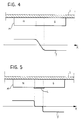
- Figure 4 shows a permanent magnet M, of ideal linear development, disposed such that two inductor poles are produced, indicated N and S, opposite a motor.
- the development of the distribution of the density of magnetic energy is represented by the function f shown in the lower part of the Figure.
- Figure 5 shows an embodiment in which the desired distribution is brought about using the same magnet shown in Figure 4 without the need for additional operations.
- an element L conducting magnetic flux is used which is applied in the central region of the permanent magnet M and thus in the transitional area separating the two magnetic poles N and S.
- the conductor element L can consist of a plate or lamination made of steel or some other material which conducts magnetic flux.
- the function of the element L is to convey the magnetic flux through itself (in practice short circuiting it) in the transitional area between the two poles N and S of the permanent magnet M. In this way, the element L ensures that the distribution f and its first derivative is zero in this transitional area.
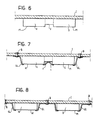
- Figure 6 illustrates an alternative embodiment in which the desired development of the distribution f is brought about by providing a notch or groove V, of a substantially rectangular shape, in correspondence with the transitional region of the permanent magnet M.
- Figure 7 shows a further alternative embodiment in which both the above-described devices are adopted, that is the notch V and the conductor element L.
- elements GL conducting the magnetic flux are also provided in correspondence with the two ends of the permanent magnet M.
- the elements GL conducting the magnetic flux enable the magnetic flux to be short-circuited in correspondence with the ends of the permanent magnet M on the casing I and also have the function of rendering the magnet M integral with the casing I.
- the conductor elements GL are in fact in the form of clips and are secured to the casing I by means of rivets, or or the like,B.
- Figure 8 shows an alternative embodiment in which one permanent magnet M is used for each pole.
- the conductor elements GL are used, similarly to the case described above, for holding the magnets M and for ensuring the desired distribution f in correspondence with their ends.
- the entire distribution of the magnetic poles of the inductor can be brought about by a magnetic tubular element having zones of permanent magnetisation alternately of opposite signs.
- the aforementioned devices can also be used in this type of embodiment.
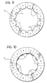
- Figures 9 and 10 in fact show (in axial view) two monolithic tubular permanent magnets M obtained by sintering. In the magnet M of Figure 9 the desired distribution is brought about by means of the notches V described above whilst in the magnet M of Figure 10 the distribution is brought about by the conductor elements L. It is evidently possible to combine the notches V with the conductor elements L also in this case.
- n c 48 (24 slots + 24 dummy slots)
- the magnet to be used has an angular opening of 38.5° ⁇ 0.5°.
Landscapes
- Engineering & Computer Science (AREA)
- Power Engineering (AREA)
- Permanent Field Magnets Of Synchronous Machinery (AREA)
- Iron Core Of Rotating Electric Machines (AREA)
- Reciprocating, Oscillating Or Vibrating Motors (AREA)
- Permanent Magnet Type Synchronous Machine (AREA)
Claims (16)
- Dauermagneten-Motor, umfassend einen Induktor (R) mit Dauermagnetmitteln, die eine Winkelverteilung von Magnetpolen (M) erzeugen können; einen vom Induktor (R) durch einen Luftspalt (T) getrennten Anker (ST) mit einer Vielzahl an Schlitzen oder Kanälen (C), die dem Luftspalt (T) gegenüberliegen;
dadurch gekennzeichnet, daß die Dauermagnetmittel (M) so geformt und angeordnet sind, daß die Verteilung der magnetischen Energiedichte (f), die im Luftspalt (T) bei Fehlen von Schlitzen (C) im Anker (ST) gespeichert werden kann, als Funktion einer linearen Koordinate (x), die entlang einer zur Achse des Motors koaxialen und im Luftspalt (T) enthaltenen Kreislinie genommen ist, Niveauübergänge in zunehmender Richtung bzw. in abnehmender Richtung bei vorher bestimmten Winkelpositionen aufweist; und daß die Schlitze (C) im Anker (ST) an Positionen hergestellt werden, die so gewählt sind, daß sich beim Betrieb, wenn sich ein Schlitz (C) in einer Winkelposition befindet, die einem Niveauübergang der Verteilung der magnetischen Energiedichte (f) entspricht, ein weiterer Schlitz (C) in einer Winkelposition befindet, die einem Niveauübergang der Verteilung der magnetischen Energiedichte (f) mit dem entgegengesetzten Vorzeichen entspricht; und daß die Dauermagnetmittel (M) so geformt und angeordnet sind, daß die Verteilung der magnetischen Energiedichte (f) im Luftspalt (T) Niveauübergänge mit einer Entwicklung aufweist, die bezüglich einer Achse asymmetrisch ist, und daß die Schlitze (C) des Ankers (ST) so geformt sind, daß jeder von ihnen die Verteilung der magnetischen Energiedichte (f) im Luftspalt (T) gemäß einer Modulierfunktion (g) modifizieren kann, die eine lokale Entwicklung aufweist, die zur durch das Zentrum des Schlitzes (C) gehenden radialen Ebene symmetrisch ist. - Motor nach Anspruch 1, dadurch gekennzeichnet, daß die Dauermagnetmittel (M) so geformt und angeordnet sind, daß die Verteilung der magnetischen Energiedichte (f) im Luftspalt (T) zwischen zwei aufeinanderfolgenden Niveauübergängen einen im wesentlichen konstanten Wert (2f0) aufweist.
- Motor nach Anspruch 1 oder Anspruch 2, wobei der Luftspalt (T) eine Breite (w) aufweist, dadurch gekennzeichnet, daß die Dauermagnetmittel (M) so im Abstand voneinander angeordnet und geformt sind, daß f(x) eine Funktion definiert, die die Verteilung der magnetischen Energiedichte darstellt, die im Luftspalt (T) bei Fehlen von Schlitzen im Anker gespeichert werden kann, wobei (x) eine lineare Koordinate ist, die entlang einer zur Achse des Motors koaxialen und im Luftspalt enthaltenen Kreislinie genommen ist, und wobei f(x) eine im wesentlichen konstante Entwicklung mit einem Wert gleich 2f0 im wesentlichen in Entsprechung mit den Magnetpolen (M) aufweist, und daß f1(x') und f2(x") zwei Funktionen definieren, die die Funktion f(x) in zwei Umgebungen darstellen, die in Entsprechung mit den Enden eines der Magnetpole (M) lokalisiert sind, wobei x' und x" zwei entlang der x-Achse genommene Koordinaten sind, und wobei die zwei Punkte (x1, x2), bei denen die Funktion f(x) einen Wert f0 annimmt, als Ursprünge angesehen werden, wobei die Funktion f(x) und die Funktionen f1(x') und f2(x") die folgenden Bedingungen erfüllen:- für zumindest einen Wert von x, in einem Bereich zwischen zwei benachbarten Magnetpolen (M), ist die Funktion f(x) im wesentlichen konstant (f'(x) = 0);- wobei (x1, x2) zwei Punkte auf der x-Achse sind, wo f(x) = f0 ist, im wesentlichen nahe zwei beliebigen Enden der Magnetpole (M), wenn sich einer der Punkte (x1, x2) in Entsprechung mit einem der Schlitze (C) befindet, wobei sich der andere der zwei Punkte (x1, x2) auch in Entsprechung mit einem dieser Schlitze (C) befindet.
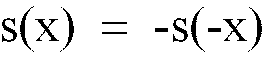
- Motor nach Anspruch 3, dadurch gekennzeichnet, daß f1(x') und f2(x") die Bedingung erfüllen:


- Motor nach Anspruch 4, dadurch gekennzeichnet, daß die Dauermagnetmittel Dauermagneten (M) umfassen, die so geformt sind, daß die Winkelöffnung für jeden der Dauermagneten (M) definiert, mögliche Abschrägungen umfassend und in Sexagesimalen ausgedrückt, wobei der Wert von β im wesentlichen durch die folgende Formel geliefert wird:
 - nc die Anzahl der Schlitze (C) ist;- p die Anzahl an Polpaaren (p) ist; und- K eine ganze Zahl ist, gewählt aus 1, 2 ..., (nc/2p-1), worin nc/2p eine ganze Zahl größer als 1 ist.
 - Motor nach einem der vorangehenden Ansprüche, dadurch gekennzeichnet, daß die Dauermagnetmittel (M) magnetische Flußleitermittel (L, GL) umfassen, die der Verteilung der magnetischen Energiedichte f(x) im Luftspalt (T) in Entsprechung mit den Niveauänderungen die gewünschte Entwicklung auferlegen können.
- Motor nach Anspruch 6, dadurch gekennzeichnet, daß die magnetischen Flußleitermittel (GL) die Dauermagneten (M) festhalten können.
- Motor nach Anspruch 7, dadurch gekennzeichnet, daß die Dauermagnetmittel einen Dauermagneten (M) mit zumindest zwei entgegengesetzten Magnetpolen (N, S) umfassen; und daß die magnetischen Flußleitermittel (L) am Dauermagnet (M) in Entsprechung mit einer Übergangszone zwischen den zwei entgegengesetzten Polen (N, S) angebracht werden.
- Motor nach Anspruch 7 oder Anspruch 8, dadurch gekennzeichnet, daß die magnetischen Flußleitermittel (L, GL) den magnetischen Fluß so hindurch leiten können, daß die magnetische Energiedichte f(x) im Luftspalt (T) in Entsprechung damit im wesentlichen null ist.
- Motor nach einem der Ansprüche 1 bis 5, dadurch gekennzeichnet, daß die Dauermagnetmittel einen Dauermagneten (M) mit mindestens zwei entgegengesetzten Magnetpolen (N, S) und einem Schlitz (V) umfassen, der dem Luftspalt (T) in Entsprechung mit einer Übergangszone zwischen den zwei entgegengesetzten Polen (N, S) gegenüberliegt.
- Motor nach einem der Ansprüche 6 bis 9, dadurch gekennzeichnet, daß die magnetischen Flußleitermittel (L, GL) aus Metall hergestellt sind.
- Motor nach Anspruch 11, dadurch gekennzeichnet, daß die magnetischen Flußleitermittel (L, GL) aus Stahlblech hergestellt sind.
- Motor nach Anspruch 4 oder Anspruch 5, dadurch gekennzeichnet, daß die Enden der Magneten (M) abgeschrägt sind.
- Motor nach Anspruch 13, dadurch gekennzeichnet, daß die Enden der Magneten (M) über eine Tiefe von etwa 1,5 w im wesentlichen 45° abgeschrägt sind.
- Motor nach einem der Ansprüche 3 bis 14, dadurch gekennzeichnet, daß der Abstand S zwischen zwei benachbarten Magneten (M) so gestaltet ist, daß

- Motor nach Anspruch 13, dadurch gekennzeichnet, daß ein Teil der Schlitze (C) keine Ankerwicklungen enthält, um den Abstand S zu verringern.
Applications Claiming Priority (2)
| Application Number | Priority Date | Filing Date | Title |
|---|---|---|---|
| ITTO930716A IT1261598B (it) | 1993-09-30 | 1993-09-30 | Motore elettrico a magneti permanenti con coppia di riluttanza ridotta |
| ITTO930716 | 1993-09-30 |
Publications (2)
| Publication Number | Publication Date |
|---|---|
| EP0647010A1 EP0647010A1 (de) | 1995-04-05 |
| EP0647010B1 true EP0647010B1 (de) | 1997-08-27 |
Family
ID=11411767
Family Applications (1)
| Application Number | Title | Priority Date | Filing Date |
|---|---|---|---|
| EP94115158A Revoked EP0647010B1 (de) | 1993-09-30 | 1994-09-27 | Dauermagneten-Elektromotor mit niedrigem pulsierenden Drehmoment |
Country Status (4)
| Country | Link |
|---|---|
| US (1) | US6181035B1 (de) |
| EP (1) | EP0647010B1 (de) |
| DE (1) | DE69405182T2 (de) |
| IT (1) | IT1261598B (de) |
Families Citing this family (42)
| Publication number | Priority date | Publication date | Assignee | Title |
|---|---|---|---|---|
| DE19633209A1 (de) * | 1995-08-28 | 1997-03-06 | Papst Motoren Gmbh & Co Kg | Verfahren und Vorrichtung zur Reduzierung des sogenannten Nutruckens bei einem Elektromotor |
| US6940205B1 (en) * | 1997-09-08 | 2005-09-06 | Matsushita Electric Industrial Co., Ltd. | Permanent magnet synchronous motor |
| US6949864B2 (en) * | 2000-04-05 | 2005-09-27 | Wavecrest Laboratories, Llc | Rotary electric motor having concentric annular members |
| JP2002112476A (ja) * | 2000-09-28 | 2002-04-12 | Hitachi Ltd | 永久磁石式回転電機 |
| EP1246349A3 (de) * | 2001-03-30 | 2005-09-07 | Japan Servo Co. Ltd. | Dauermagnetmotor |
| US6784582B1 (en) * | 2001-11-19 | 2004-08-31 | Valeo Electrical Systems, Inc. | Magnet shaping and pole concentration for reduction of cogging torque in permanent magnet motors |
| US6727630B1 (en) | 2002-07-31 | 2004-04-27 | Wavecrest Laboratories, Llc. | Rotary permanent magnet electric motor with varying air gap between interfacing stator and rotor elements |
| US6822368B2 (en) * | 2002-06-04 | 2004-11-23 | Wavecrest Laboratories, Llc | Rotary permanent magnet electric motor having stator pole shoes of varying dimensions |
| US6727629B1 (en) | 2002-06-04 | 2004-04-27 | Wavecrest Laboratories, Llc | Rotary electric motor having a plurality of shifted stator poles and/or rotor poles |
| US6717323B1 (en) | 2002-06-04 | 2004-04-06 | Wavecrest Laboratories, Llc | Rotary electric motor having a plurality of skewed stator poles and/or rotor poles |
| US20040021437A1 (en) * | 2002-07-31 | 2004-02-05 | Maslov Boris A. | Adaptive electric motors and generators providing improved performance and efficiency |
| US20050045392A1 (en) * | 2002-07-31 | 2005-03-03 | Maslov Boris A. | In-wheel electric motors |
| US20040263099A1 (en) * | 2002-07-31 | 2004-12-30 | Maslov Boris A | Electric propulsion system |
| US20050046375A1 (en) * | 2002-07-31 | 2005-03-03 | Maslov Boris A. | Software-based adaptive control system for electric motors and generators |
| US20050127856A1 (en) * | 2002-07-31 | 2005-06-16 | Wavecrest Laboratories | Low-voltage electric motors |
| WO2004017489A1 (ja) * | 2002-08-16 | 2004-02-26 | Yamaha Hatsudoki Kabushiki Kaisha | 回転電機のマグネット |
| JP4408674B2 (ja) * | 2003-09-29 | 2010-02-03 | 愛三工業株式会社 | 燃料ポンプ |
| JP2005223977A (ja) * | 2004-02-04 | 2005-08-18 | Matsushita Electric Ind Co Ltd | 電動ファン |
| US7635932B2 (en) * | 2004-08-18 | 2009-12-22 | Bluwav Systems, Llc | Dynamoelectric machine having heat pipes embedded in stator core |
| US7687945B2 (en) * | 2004-09-25 | 2010-03-30 | Bluwav Systems LLC. | Method and system for cooling a motor or motor enclosure |
| US7385328B2 (en) * | 2006-05-23 | 2008-06-10 | Reliance Electric Technologies, Llc | Cogging reduction in permanent magnet machines |
| JP2008043031A (ja) * | 2006-08-04 | 2008-02-21 | Mabuchi Motor Co Ltd | リング形状界磁マグネットに薄肉部を形成した小型モータ |
| TWI337439B (en) * | 2006-12-21 | 2011-02-11 | Delta Electronics Inc | Permanent magnet rotary structure of electrical machinery and method for determining the structure thereof |
| TWI343689B (en) * | 2006-12-28 | 2011-06-11 | Delta Electronics Inc | Permanent magnet rotary structure of electric machinery |
| WO2008141214A1 (en) | 2007-05-09 | 2008-11-20 | Motor Excellence, Llc. | Electrical output generating devices and driven electrical devices with reduced flux leakage using permanent magnet components, and methods of making and using the same |
| US7989084B2 (en) * | 2007-05-09 | 2011-08-02 | Motor Excellence, Llc | Powdered metal manufacturing method and devices |
| JP2012508549A (ja) | 2008-11-03 | 2012-04-05 | モーター エクセレンス, エルエルシー | 横方向および/またはコンミュテート式磁束システムの固定子の概念 |
| DE102009028036A1 (de) * | 2009-07-27 | 2011-02-03 | Robert Bosch Gmbh | Elektromotor mit Permanentmagnet-Erregung |
| NZ582764A (en) * | 2010-01-20 | 2012-04-27 | Wellington Drive Technologies Ltd | Rotor or stator with magnets contacting flux returns |
| CN102959832B (zh) * | 2010-03-15 | 2016-11-16 | 电扭矩机器股份有限公司 | 具有相偏移的横向和/或换向通量系统 |
| WO2011115632A1 (en) | 2010-03-15 | 2011-09-22 | Motor Excellence Llc | Transverse and/or commutated flux systems configured to provide reduced flux leakage, hysteresis loss reduction, and phase matching |
| WO2011115633A1 (en) | 2010-03-15 | 2011-09-22 | Motor Excellence Llc | Transverse and/or commutated flux system for electric bicycles |
| EP2641316B1 (de) | 2010-11-17 | 2019-02-13 | Motor Excellence, LLC | Quer- oder mischflusssysteme mit segmentierten statorlamellen |
| WO2012067896A2 (en) | 2010-11-17 | 2012-05-24 | Motor Excellence, Llc | Transverse and/or commutated flux systems having laminated and powdered metal portions |
| WO2012067895A2 (en) | 2010-11-17 | 2012-05-24 | Motor Excellence, Llc | Transverse and/or commutated flux system coil concepts |
| JP2012222909A (ja) * | 2011-04-06 | 2012-11-12 | Asmo Co Ltd | モータ |
| US10374471B2 (en) | 2012-07-27 | 2019-08-06 | Regal Beloit America, Inc. | Methods, systems, and apparatus for reducing cogging torque in an electric machine |
| EP3026798B1 (de) | 2014-11-25 | 2020-10-14 | Black & Decker Inc. | Bürstenloser motor für ein elektrowerkzeug |
| CN105005692B (zh) * | 2015-07-08 | 2018-09-28 | 三峡大学 | 一种基于解析法的永磁电机磁场分析与转矩计算方法 |
| US10328566B2 (en) | 2015-10-14 | 2019-06-25 | Black & Decker Inc. | Brushless motor system for power tools |
| FR3067880B1 (fr) * | 2017-06-15 | 2020-07-17 | Moteurs Leroy-Somer | Machine electrique tournante |
| US10965176B2 (en) | 2019-01-15 | 2021-03-30 | Mcmillan Electric Company | Electric motors with pole biasing |
Family Cites Families (28)
| Publication number | Priority date | Publication date | Assignee | Title |
|---|---|---|---|---|
| US3178599A (en) | 1962-01-23 | 1965-04-13 | Gen Precision Inc | Permanent magnet d.c. torquer |
| DE2419432C3 (de) | 1974-04-23 | 1985-05-09 | Papst-Motoren GmbH & Co KG, 7742 St Georgen | Kollektorloser Gleichstrommotor mit einem Stator und mit einem permanentmagnetischen Rotor |
| US4091300A (en) | 1975-08-30 | 1978-05-23 | Lucas Industries Limited | Permanent magnet electrical machines |
| GB1604121A (en) * | 1977-04-08 | 1981-12-02 | Sony Corp | Dc motors |
| GB1603969A (en) | 1977-05-26 | 1981-12-02 | Matsushita Electric Industrial Co Ltd | Rotary electrical machine |
| US4341969A (en) | 1980-12-01 | 1982-07-27 | Honeywell Inc. | Direct current motor with improved pole piece that reduces cogging |
| GB2127231B (en) * | 1982-07-27 | 1987-08-19 | Papst Motoren Gmbh & Co Kg | Drive motor unit for signal-processing devices especially information-storage-disk devices |
| EP0112636B1 (de) * | 1982-11-22 | 1987-03-18 | LUCAS INDUSTRIES public limited company | Dynamoelektrische Maschine mit rotierendem Dauermagnet |
| US4504755A (en) | 1983-11-03 | 1985-03-12 | Kollmorgen Technologies Corporation | Rotor reluctance notch for cogging control |
| KR920000717B1 (ko) | 1984-07-25 | 1992-01-20 | 가부시기가이샤 히다찌세이사꾸쇼 | 영구자석전기 |
| JPS6158456A (ja) * | 1984-08-30 | 1986-03-25 | Mitsubishi Chem Ind Ltd | モ−タ− |
| JPH0695813B2 (ja) * | 1984-08-30 | 1994-11-24 | 三菱製鋼株式会社 | モーター |
| US4641080A (en) * | 1984-10-18 | 1987-02-03 | Sundstrand Corporation | Permanent magnet generator with fault detection |
| JPS61106035A (ja) * | 1984-10-30 | 1986-05-24 | Toshiba Corp | スロツト鉄心形直流モ−タ |
| JPS62114454A (ja) * | 1985-11-11 | 1987-05-26 | Matsushita Electric Ind Co Ltd | ブラシレス電動機 |
| DE3700774C2 (de) | 1986-01-13 | 1998-11-12 | Papst Motoren Gmbh & Co Kg | Kollektorlose Gleichstrommaschine |
| JPS633638A (ja) * | 1986-06-23 | 1988-01-08 | Tamagawa Seiki Co Ltd | ブラシレス直流モ−タ |
| US4733118A (en) | 1986-09-22 | 1988-03-22 | Hhk Inc. | Low damping torque brushless D.C. motor |
| JPS6439250A (en) * | 1987-08-03 | 1989-02-09 | Daikin Ind Ltd | Rotating power machine |
| JPS6464548A (en) | 1987-09-03 | 1989-03-10 | Fanuc Ltd | Rotor construction of synchronous motor |
| NL8801700A (nl) | 1988-07-05 | 1990-02-01 | Philips Nv | Electrische meerpolige machine. |
| US5237231A (en) * | 1989-10-19 | 1993-08-17 | General Electric Company | Structured product dynamoelectric machine |
| JPH03106869U (de) * | 1990-02-16 | 1991-11-05 | ||
| US5095238A (en) * | 1990-04-03 | 1992-03-10 | Minebea Co., Ltd. | Brushless dc motor and rotor magnet |
| SE466080B (sv) * | 1990-04-24 | 1991-12-09 | Elmo Ab | Synkronmaskin |
| US4994702A (en) | 1990-07-20 | 1991-02-19 | Mitsubishi Kasei Corporation | Motor |
| JPH0756616Y2 (ja) * | 1990-08-07 | 1995-12-25 | 株式会社ゼクセル | モータのロータマグネットの着磁構造 |
| IT1245432B (it) | 1991-03-04 | 1994-09-20 | Magneti Marelli Spa | Perfezionamenti nei motori brushless trifasi con controllo ad una semionda |
-
1993
- 1993-09-30 IT ITTO930716A patent/IT1261598B/it active IP Right Grant
-
1994
- 1994-09-27 EP EP94115158A patent/EP0647010B1/de not_active Revoked
- 1994-09-27 DE DE69405182T patent/DE69405182T2/de not_active Revoked
- 1994-09-29 US US08/314,994 patent/US6181035B1/en not_active Expired - Fee Related
Also Published As
| Publication number | Publication date |
|---|---|
| IT1261598B (it) | 1996-05-23 |
| EP0647010A1 (de) | 1995-04-05 |
| DE69405182T2 (de) | 1998-03-12 |
| ITTO930716A1 (it) | 1995-03-30 |
| ITTO930716A0 (it) | 1993-09-30 |
| DE69405182D1 (de) | 1997-10-02 |
| US6181035B1 (en) | 2001-01-30 |
Similar Documents
| Publication | Publication Date | Title |
|---|---|---|
| EP0647010A1 (de) | Dauermagneten-Elektromotor mit niedrigem pulsierenden Drehmoment | |
| US10404115B2 (en) | Rotary electric machine | |
| Islam et al. | Issues in reducing the cogging torque of mass-produced permanent-magnet brushless DC motor | |
| EP2515417B1 (de) | Synchrone Permanentmagnetmaschine | |
| CN107925338B (zh) | 电动机磁性组合 | |
| KR101083695B1 (ko) | 영구자석 내장형 회전모터의 극호율 결정방법 및 영구자석내장형 회전모터 | |
| US6031304A (en) | Motor structure | |
| CN102570636A (zh) | 电动机 | |
| US20050023927A1 (en) | Brushless DC motor and method of manufacturing brushless DC motor | |
| EP1684400A1 (de) | Rotierende elektrische Maschine | |
| US10340780B2 (en) | Transverse flux machine | |
| US4566179A (en) | Core element for electrodynamic rotary machine | |
| JP3344645B2 (ja) | 永久磁石を用いたモータ | |
| JP2019140892A (ja) | 磁石及び回転電機 | |
| JP2004357368A (ja) | 永久磁石を利用したモータ | |
| US5315198A (en) | Synchronous machine | |
| EP4131728A1 (de) | Motorstator, antriebsmotor und elektrisches fahrzeug | |
| US6548919B2 (en) | Linear motor | |
| JPH07336967A (ja) | 軸方向空隙形同期モータ | |
| JP3550678B2 (ja) | リニアモータ | |
| US7095141B2 (en) | Travelling field synchronous AC motor | |
| KR102128715B1 (ko) | 모터 | |
| EP1311056A1 (de) | Linearmotor | |
| US20080290754A1 (en) | AC Motor | |
| CN1065685C (zh) | 部件之间可以相互运动的电动机 |
Legal Events
| Date | Code | Title | Description |
|---|---|---|---|
| PUAI | Public reference made under article 153(3) epc to a published international application that has entered the european phase |
Free format text: ORIGINAL CODE: 0009012 |
|
| AK | Designated contracting states |
Kind code of ref document: A1 Designated state(s): DE FR |
|
| 17P | Request for examination filed |
Effective date: 19950324 |
|
| 17Q | First examination report despatched |
Effective date: 19960216 |
|
| GRAG | Despatch of communication of intention to grant |
Free format text: ORIGINAL CODE: EPIDOS AGRA |
|
| GRAH | Despatch of communication of intention to grant a patent |
Free format text: ORIGINAL CODE: EPIDOS IGRA |
|
| GRAH | Despatch of communication of intention to grant a patent |
Free format text: ORIGINAL CODE: EPIDOS IGRA |
|
| GRAA | (expected) grant |
Free format text: ORIGINAL CODE: 0009210 |
|
| AK | Designated contracting states |
Kind code of ref document: B1 Designated state(s): DE FR |
|
| REF | Corresponds to: |
Ref document number: 69405182 Country of ref document: DE Date of ref document: 19971002 |
|
| ET | Fr: translation filed | ||
| REG | Reference to a national code |
Ref country code: FR Ref legal event code: TP |
|
| PLBI | Opposition filed |
Free format text: ORIGINAL CODE: 0009260 |
|
| PLBF | Reply of patent proprietor to notice(s) of opposition |
Free format text: ORIGINAL CODE: EPIDOS OBSO |
|
| 26 | Opposition filed |
Opponent name: ROBERT BOSCH GMBH Effective date: 19980526 |
|
| PGFP | Annual fee paid to national office [announced via postgrant information from national office to epo] |
Ref country code: FR Payment date: 19980930 Year of fee payment: 5 |
|
| PGFP | Annual fee paid to national office [announced via postgrant information from national office to epo] |
Ref country code: DE Payment date: 19981027 Year of fee payment: 5 |
|
| PLBF | Reply of patent proprietor to notice(s) of opposition |
Free format text: ORIGINAL CODE: EPIDOS OBSO |
|
| RDAH | Patent revoked |
Free format text: ORIGINAL CODE: EPIDOS REVO |
|
| RDAG | Patent revoked |
Free format text: ORIGINAL CODE: 0009271 |
|
| STAA | Information on the status of an ep patent application or granted ep patent |
Free format text: STATUS: PATENT REVOKED |
|
| 27W | Patent revoked |
Effective date: 19990101 |