EP0647041A1 - Radiodatenempfänger mit durch Programmartdaten gesteuerter Stromversorgungsschaltung - Google Patents
Radiodatenempfänger mit durch Programmartdaten gesteuerter Stromversorgungsschaltung Download PDFInfo
- Publication number
- EP0647041A1 EP0647041A1 EP94307049A EP94307049A EP0647041A1 EP 0647041 A1 EP0647041 A1 EP 0647041A1 EP 94307049 A EP94307049 A EP 94307049A EP 94307049 A EP94307049 A EP 94307049A EP 0647041 A1 EP0647041 A1 EP 0647041A1
- Authority
- EP
- European Patent Office
- Prior art keywords
- signal
- broadcasting
- demodulating
- supplied
- unit
- Prior art date
- Legal status (The legal status is an assumption and is not a legal conclusion. Google has not performed a legal analysis and makes no representation as to the accuracy of the status listed.)
- Granted
Links
Images


Classifications
-
- H—ELECTRICITY
- H04—ELECTRIC COMMUNICATION TECHNIQUE
- H04H—BROADCAST COMMUNICATION
- H04H40/00—Arrangements specially adapted for receiving broadcast information
- H04H40/18—Arrangements characterised by circuits or components specially adapted for receiving
-
- H—ELECTRICITY
- H04—ELECTRIC COMMUNICATION TECHNIQUE
- H04B—TRANSMISSION
- H04B1/00—Details of transmission systems, not covered by a single one of groups H04B3/00 - H04B13/00; Details of transmission systems not characterised by the medium used for transmission
- H04B1/06—Receivers
- H04B1/16—Circuits
- H04B1/20—Circuits for coupling gramophone pick-up, recorder output, or microphone to receiver
-
- H—ELECTRICITY
- H04—ELECTRIC COMMUNICATION TECHNIQUE
- H04H—BROADCAST COMMUNICATION
- H04H20/00—Arrangements for broadcast or for distribution combined with broadcast
- H04H20/28—Arrangements for simultaneous broadcast of plural pieces of information
-
- H—ELECTRICITY
- H04—ELECTRIC COMMUNICATION TECHNIQUE
- H04H—BROADCAST COMMUNICATION
- H04H60/00—Arrangements for broadcast applications with a direct linking to broadcast information or broadcast space-time; Broadcast-related systems
- H04H60/09—Arrangements for device control with a direct linkage to broadcast information or to broadcast space-time; Arrangements for control of broadcast-related services
- H04H60/14—Arrangements for conditional access to broadcast information or to broadcast-related services
- H04H60/15—Arrangements for conditional access to broadcast information or to broadcast-related services on receiving information
-
- H—ELECTRICITY
- H04—ELECTRIC COMMUNICATION TECHNIQUE
- H04H—BROADCAST COMMUNICATION
- H04H60/00—Arrangements for broadcast applications with a direct linking to broadcast information or broadcast space-time; Broadcast-related systems
- H04H60/09—Arrangements for device control with a direct linkage to broadcast information or to broadcast space-time; Arrangements for control of broadcast-related services
- H04H60/14—Arrangements for conditional access to broadcast information or to broadcast-related services
- H04H60/16—Arrangements for conditional access to broadcast information or to broadcast-related services on playing information
-
- H—ELECTRICITY
- H04—ELECTRIC COMMUNICATION TECHNIQUE
- H04H—BROADCAST COMMUNICATION
- H04H60/00—Arrangements for broadcast applications with a direct linking to broadcast information or broadcast space-time; Broadcast-related systems
- H04H60/35—Arrangements for identifying or recognising characteristics with a direct linkage to broadcast information or to broadcast space-time, e.g. for identifying broadcast stations or for identifying users
- H04H60/47—Arrangements for identifying or recognising characteristics with a direct linkage to broadcast information or to broadcast space-time, e.g. for identifying broadcast stations or for identifying users for recognising genres
-
- H—ELECTRICITY
- H04—ELECTRIC COMMUNICATION TECHNIQUE
- H04H—BROADCAST COMMUNICATION
- H04H2201/00—Aspects of broadcast communication
- H04H2201/10—Aspects of broadcast communication characterised by the type of broadcast system
- H04H2201/13—Aspects of broadcast communication characterised by the type of broadcast system radio data system/radio broadcast data system [RDS/RBDS]
-
- Y—GENERAL TAGGING OF NEW TECHNOLOGICAL DEVELOPMENTS; GENERAL TAGGING OF CROSS-SECTIONAL TECHNOLOGIES SPANNING OVER SEVERAL SECTIONS OF THE IPC; TECHNICAL SUBJECTS COVERED BY FORMER USPC CROSS-REFERENCE ART COLLECTIONS [XRACs] AND DIGESTS
- Y02—TECHNOLOGIES OR APPLICATIONS FOR MITIGATION OR ADAPTATION AGAINST CLIMATE CHANGE
- Y02D—CLIMATE CHANGE MITIGATION TECHNOLOGIES IN INFORMATION AND COMMUNICATION TECHNOLOGIES [ICT], I.E. INFORMATION AND COMMUNICATION TECHNOLOGIES AIMING AT THE REDUCTION OF THEIR OWN ENERGY USE
- Y02D30/00—Reducing energy consumption in communication networks
- Y02D30/70—Reducing energy consumption in communication networks in wireless communication networks
Definitions
- the present invention relates to a reception apparatus, a signal reproducing apparatus using the reception apparatus and a control method thereof. More particularly, this invention relates to a reception apparatus for receiving data multiplex broadcasting, a signal reproducing apparatus using the reception apparatus and a control method thereof.
- RDS broadcast FM broadcasting based on the RDS
- a baseband signal of an FM broadcast signal is transmitted in the multiplexed form of a main signal M (sum signal L+R in the case of stereo broadcasting) and a stereo signal S (difference signal L-R), and a stereo pilot signal P is assigned to a frequency band of 19 kHz. This is the same as the ordinary FM stereo broadcast signal.
- a sub-carrier signal SC is assigned to a frequency band of 57 kHz which is three times as high as the frequency of the stereo pilot signal P .
- RDS data R is modulated by the sub-carrier signal SC .
- the RDS data R is composed of grouped digital data as shown in FIGURE 2. As shown in FIGURE 2, one group is composed of 4 blocks and each block is composed of 26-bit data. Of 26 bits, 16 bits are assigned to practical data representing broadcast contents or the like, and remaining 10 bits are assigned to an error correction code. The 16-bit data in respective blocks are defined individually.
- Data transmitted according to the above-mentioned format are mainly as follows: PS code ... Character data representing broadcast station name PI code ... ID (identification) code of broadcast program, country name code, program code, etc. TP code ... Traffic information broadcast station ID signal TA code ... Traffic information broadcasting ID signal PTY code ... Program content ID code representing contents of news, sports and music of each genre EON code ... ID code representing broadcast contents of other broadcast station The listener can learn the present broadcast contents of a certain broadcast station by using these codes and also can learn broadcast contents of other broadcast station.
- the listener detect that traffic information is broadcast by a broadcasting station (its own or other broadcasting station) represented by other data (PS code, EON code, etc.) transmitted simultaneously.
- a broadcasting station its own or other broadcasting station
- other data PS code, EON code, etc.
- RDS broadcasting When the data based on the RDS broadcasting is used as described above, it is necessary for the listener to constantly listen to FM broadcasting (RDS broadcasting) of any broadcasting station. If the FM broadcasting or RDS broadcasting were not received, RDS data would not be received. For this reason, unless traffic information is broadcast by any broadcasting station for a long period of time when the listener wishes to hear traffic information, for example, the listener should keep listening to broadcasting of other broadcasting content for a long period of time until any broadcasting station starts broadcasting traffic information.
- RDS broadcasting FM broadcasting
- a signal reproducing apparatus for receiving a broadcasting signal transmitted in the form of a multiplex signal added with data concerning classification of broadcasting content.
- the signal reproducing apparatus includes a demodulating unit, a signal processing unit, an identification unit and a control unit.
- the demodulating unit demodulates a received broadcasting signal and also demodulates data concerning classification of broadcasting content contained in the received broadcasting signal.
- the signal processing unit is supplied with an output signal from the demodulating unit and processes and outputs the output signal supplied thereto in a predetermined signal processing fashion.
- the identification unit is supplied with demodulated data from the demodulating unit and identifies the demodulated data supplied thereto.
- the control unit controls the supply of power to the demodulating unit, the signal processing unit and the identification unit.
- the control unit energizes the demodulating unit and the identification unit when the power switch of the apparatus is turned off under the condition that a mode for receiving broadcasting of a predetermined broadcasting classification represented by the data concerning the broadcasting content is set. Also, when the identified result from the identification unit shows that the broadcasting of the predetermined broadcasting classification is carried out, the control unit generates a control signal which effect the channel selection based on the identified result from the identification unit and energises the signal processing unit.
- a reception apparatus for receiving a broadcasting signal transmitted in the form of a multiplex signal added with data concerning classification of broadcasting content.
- the reception apparatus includes a reception unit, a demodulating unit, a data demodulating unit and a control unit.
- the reception unit receives a broadcasting signal transmitted thereto.
- the demodulating unit demodulates an output signal supplied thereto from the reception unit.
- the data demodulating unit demodulates data concerning classification of broadcasting content contained in the output signal from the reception unit.
- the control unit is supplied with the demodulated data from the data demodulating unit and identifies the demodulated data supplied thereto.
- the reception unit, the data demodulating unit and the control unit are energized when the power switch of the apparatus is turned off under the condition that a mode for receiving broadcasting of a predetermined broadcasting classification represented by the data concerning the broadcasting content is set. Also, under this state, when it is detected by the control unit that the broadcasting of the predetermined broadcasting classification is carried out, the control unit generates a detected signal representing that the broadcasting of the predetermined broadcasting classification is carried out and the reception unit carries out channel selection operation.
- a control method of a signal reproducing apparatus including a reception unit and a signal processing unit.
- the reception unit receives a broadcasting signal transmitted in the form of a multiplex signal added with data concerning classification of broadcasting content.
- the reception unit includes a demodulating unit for demodulating a received broadcasting signal and the data concerning classification of broadcasting content contained in the received broadcasting signal and an identification unit for identifying demodulated data supplied thereto.
- the signal processing unit is supplied with an output signal from the demodulating unit.
- the present invention even under the condition that the power switch of the reception unit, the reception apparatus or the signal reproducing apparatus is turned off, if the transmission of the broadcasting signal added with the data concerning the classification of the previously-set broadcasting content is started, it is possible to receive and automatically reproduce the broadcasting signal transmitted in the form of the multiplex signal added with the data concerning the classification of the broadcasting content that is started being broadcast by carrying out predetermined setting.
- a signal reproducing apparatus a reception apparatus and a control method of controlling a signal reproducing apparatus in which the above-mentioned problems can be solved.
- the signal reproducing apparatus is applied to the FM reception apparatus for receiving the aforementioned RDS broadcasting.
- this FM reception apparatus is generally formed as a system stereo apparatus.
- the system stereo apparatus comprises a tuner 10, an amplifying apparatus 20, a CD (compact disc) player 2, a tape deck 3 and left and right speakers 4L and 4R.
- the FM radio broadcasting such as the RDS broadcasting or the like can be received by the tuner 10.
- a circuit arrangement of the tuner 10 will be described below.
- a signal received at an FM antenna 1 is supplied to a front end circuit 11 provided within the tuner 10.
- the front end circuit 11 is supplied with a channel selection frequency signal from a PLL (phase-locked loop) circuit 12. Then, the front end circuit 11 mixes the channel selection frequency signal to an input signal supplied thereto from the FM antenna 1 to provide an intermediate frequency (IF) signal of a broadcast wave with a predetermined frequency.
- PLL phase-locked loop
- the intermediate frequency signal from the front end circuit 11 is supplied through an intermediate frequency amplifying (IF AMP) circuit 13 to an FM detecting (FM DET) circuit 14 and is thereby detected.
- a detected signal from the FM detector 14 is supplied to a multiplexer (MPX) 15 which demodulates the detected signal supplied thereto to provide left and right stereo signals.
- the left and right stereo signals are supplied to a function switching circuit 25 provided within the amplifying apparatus 20.
- the detected signal output from the FM detecting circuit 14 is also supplied to an RDS data demodulating (RDS DATA DEMOD) circuit 16.
- the RDS demodulating circuit 16 demodulates the RDS data which was modulated by the sub-carrier signals SC shown in FIGURE 2, and supplies demodulated data to a control (CONT) circuit 17 formed of a microcomputer provided within the tuner 10.
- the control circuit 17 performs control operation concerning reception operation, such as control of a reception frequency, of the tuner 10.
- the control circuit 17 controls a frequency of the channel selection signal output from the PLL circuit 12 based on a control signal supplied thereto from the amplifying apparatus 20 to carry out a reception processing of FM broadcasting with a predetermined frequency. Further, the control circuit 17 identifies contents of data supplied thereto from the RDS data demodulating circuit 16 and supplies identified result to the amplifying apparatus 20. Depending on the set mode, the control circuit 17 automatically switches the reception frequency based on the identified data.
- the amplifying apparatus 20 switches audio signals supplied thereto from the tuner 10, the CD player 2 and the tape deck 3, i.e., switches function modes, and processes the switched audio signal, such as amplifying the audio signal so that the audio signal can be output. Then, the amplifying apparatus 20 supplies the thus processed audio signal to the left and right speakers 4L, 4R.
- the amplifying apparatus 20 includes a control (CONT) circuit 21 formed of a microcomputer.
- the control circuit 21 is connected with control circuits or controllers (each composed of a microcomputer) of other equipments, such as the tuner 10, the CD player 2 and the tape deck 3 via bus lines.
- the tuner 10, the CD player 2 and the tape deck 3 can be operated under the control of the control circuit 21.
- the control circuit 21 is connected with a plurality of keys 22 and information obtained when the key 22 is operated is supplied to the control circuit 21.
- the control circuit 21 controls operation of the circuit designated by the operation of the key 22 based on the information supplied thereto from the key 22.
- the listener can set various operation modes, such as an automatic channel selection mode or the like,which will be described later on, in addition to ordinary operation, such as to switch function modes, to switch reception frequencies at the tuner 10, to control volume and to energize and deenergize the whole system of the system stereo apparatus by using the keys 22.
- the amplifying apparatus 20 Under the control of the control circuit 21, the amplifying apparatus 20 is operated so that the function control circuit 23 switches input audio signals and a power control circuit 24 processes audio output signals.
- the function switching circuit 25 switches input audio signals under the control of the function control circuit 23. Specifically, under the control of the function control circuit 23, the function switching circuit 25 switches and supplies the input audio signal to a signal processing circuit 26.
- the audio signal selected by the function switching circuit 25 can be directly supplied to the tape deck 3 and the tape deck 3 can record the audio signal supplied thereto. Furthermore, it is possible to select other input audio signals apart from the audio signal supplied to the tape deck 3 and the audio signal supplied to the signal processing circuit 26.
- the signal processing circuit 26 receives the audio signal selected by the function switching circuit 25 and effects necessary audio signal output processing, such as amplifying or the like on the audio signal supplied thereto under the control of the power control circuit 24. In this case, the signal processing circuit 26 controls output volume based on volume control data supplied thereto from the control circuit 21 through the power control circuit 24.
- the control circuit 21 can perform various control operations based on the RDS data supplied thereto from the tuner 10 after the tuner 10 had received and identified the RDS data. Operation modes that are available in this embodiment are as follows:
- the original channel selection frequency is restored. Specifically, in the case of the RDS forced channel selection mode, the channel selection frequency of the original broadcasting station is restored after the broadcasting of the previously-registered broadcast contents was finished under the control of the control circuit 21. Also, it is possible to set any of the above-mentioned operation modes by operating any of the keys 22.
- the function switching circuit 25 In the case of the RDS forced function switching mode, under the control of the control circuit 21, the function switching circuit 25 is operated so that the original reproduced audio signal is output after the broadcasting of the previously-registered broadcast contents was finished. In this case, if the function switching circuit 25 switches the function mode so that audio signal reproduced from the disc or the tape by the CD player 2 or the tape deck 3 is output, under the control of the control circuit 21, the CD player 2 or the tape deck 3 is set in the pause mode when the broadcasting audio signal is started being output in the RDS forced function switching mode.
- the CD player 2 or the tape deck 3 starts reproducing the disc or the tape from the position at which the CD player 2 or the tape deck 3 was set in the pause mode to stop the reproduction of the disc or the tape temporarily.
- the system stereo apparatus In the case of the RDS forced power switch on mode, under the control of the control circuit 21, the system stereo apparatus is de-energized so that no sounds are emanated from the speakers 4L, 4R at all after the broadcasting of the previously-registered broadcast contents was finished. It is possible for the listener to set the RDS forced power switch on mode by operating predetermined keys of the keys 22 when the whole of the system stereo apparatus is de-energized.
- the tape deck 3 is de-energized to stop recording the audio signal on the tape after the broadcasting of the previously-registered broadcasting contents was finished. Also, under the control of the control circuit 21, the power switch is turned off when the tape deck 3 is automatically energized to start recording the audio signal on the tape after the tape deck 3 had been in its off state.
- the function switching circuit 25 may be de-energized and the audio signal reproduced from the compact disc by the CD player 2 may be emanated from the speakers 4L, 4R as sounds.
- the function switching circuit 25 may be energized to switch the function mode so that demodulated RDS broadcasting audio signal is output from the speakers 4L, 4R as sounds instead of the sounds reproduced from the compact disc by the CD player 2.
- the control circuit 21 judges output volume level that was set at that time, and controls volume level so that sounds of proper volume level may be emanated from the speakers 4L, 4R if it is determined that the level of the volume control is lowered completely or that the volume level is smaller that appropriate volume level.
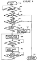
- step 101 sounds of any equipment are emanated from the left and right speakers 4L, 4R under the condition that respective equipments are energized under the control of the control circuit 21 in the amplifying apparatus 20. It is determined in the next decision 102 by the control circuit 21 whether or not the power key of the keys 22 is depressed to de-energize the system stereo apparatus. If the power key is depressed as represented by a YES at decision step 102, then the processing proceeds to the next decision step 103. It is determined in decision step 103 by the control circuit 21 whether or not any one of the modes in which the broadcasting audio signal of broadcasting content registered based on RDS data is output (or recorded) is set. These modes will be generally referred to hereinafter as "EON standby mode".
- step 104 the processing proceeds to step 104, whereat respective equipments, such as the tuner 10, the amplifying apparatus 20, the CD player 2 and the tape deck 3 are de-energized.
- respective equipments such as the tuner 10, the amplifying apparatus 20, the CD player 2 and the tape deck 3 are de-energized.
- the supply of power to respective portions of the equipments is substantially completely stopped except circuits that should be constantly energized, such as a clock circuit and a remote control signal sensing circuit (both of which are not shown).
- step 105 it is determined in decision step 105 whether or not the EON standby mode from the de-energized state is set, or whether or not the RDS forced power switch on mode or the RDS automatic recording mode from the deenergized state is set. If the EON standby mode from the deenergized state is not set as represented by a NO at decision step 105, then the processing proceeds to step 104, whereat the respective equipments are de-energized similarly to step 103.
- step 106 If the EON standby mode from the de-energized state is set as represented by a YES at decision step 105, then the processing proceeds to the next decision step 106. It is determined in decision step 106 whether or not the RDS broadcasting is now received by the tuner 10. If FM broadcasting on which the RDS data is not superimposed is received, or the tuner 10 is de-energized as represented by a NO at decision step 106, then the processing proceeds to step 107. In step 107, control command is supplied to the control circuit 17 of the tuner 10 so that the tuner 10 may receive any RDS broadcasting.
- respective equipments are deenergized in the EON standby mode.
- the circuits that are required by the tuner 10 to receive and identify RDS data i.e., the front end circuit 11 to the data demodulating circuits 16, the PLL circuit 12, the control circuit 17 and the control circuit 21 provided within the amplifying apparatus 20 are energized.
- the control circuit 17 provided within the tuner 10 whether or not any broadcasting station starts broadcasting of desired classification of broadcasting content based on received RDS data. If the broadcasting station starts broadcasting of the desired broadcasting classification as represented by a YES at decision step 109, then the processing proceeds to the next step 110, whereat the whole of the system stereo apparatus is energized under the control of the control circuit 21 provided within the amplifying apparatus 20. Also, if the function mode is not switched to the tuner 10, then the function mode is switched to the tuner 10 (except when only the RDS broadcasting is recorded on the tape by the tape deck 3). At that time, the control circuit 21 automatically adjusts the volume control such that the level of output volume becomes proper volume level. In the case of the mode in which the RDS broadcasting is recorded on the tape by the tape deck 3, the tape deck 3 is placed in the state corresponding to the operation mode under the control of the control circuit 21.
- step 111 It is determined in the next decision step 111 by the RDS data thus received whether or not the broadcasting of the desired broadcasting classification, i.e., the broadcasting of the currently received broadcasting classification is finished. If it is determined in decision step 111 based on the RDS code that the broadcasting of the currently received broadcasting classification is finished, then the processing returns to step 108, whereat the power switch of the system stereo apparatus is turned off in the EON standby mode. At that time, if the function mode of the system stereo apparatus were switched by the function switching circuit 25 in the immediately-preceding step 110, the function switching circuit 25 would switch the function mode of the system stereo apparatus to the original function mode under the control of the control circuit 21. Similarly, if the output volume level were changed in the immediately-preceding step 110, the volume control would return volume level to the original volume level under the control of the control circuit 21.
- control circuit 21 in the amplifying apparatus 20 carries out various control operations, such as operation modes shown in the flowchart of FIGURE 4, based on the RDS data received and identified by the tuner 10 as described above
- the present invention is not limited thereto and the control circuit 17 in the tuner 10 can control various operations based on these RDS data, i.e., operations in order to execute the RDS forced channel selection mode, the RDS forced function switching mode, the RDS forced power switch on mode and the RDS automatic recording mode.
- the control circuit 17 in the tuner 10 identifies demodulated RDS data supplied thereto from the RDS data demodulating circuit 16.
- control circuit 17 supplies the channel selection control signal to the PLL circuit 12 and also supplies the control signal corresponding to each operation mode to the control circuit 21 of the amplifying apparatus 20.
- the control signals that are supplied from the control circuit 17 to the control circuit 21 are function switching control signals used to execute operations on the flowchart of FIGURE 4, such as the control signal for energizing respective units other than the control circuit 21 of the amplifying apparatus 20 to place the amplifying apparatus 20 in the operable state if the operation mode is the RDS forced power switch on mode.
- a control signal is supplied to a control unit or controller (not shown) of the tape deck 3 through the control circuit 21 of the amplifying apparatus 20. While in that case the amplifying apparatus 20 is directly supplied with the control signal from the control circuit 17 of the tuner 10 as described above, the control circuit or controller of the CD player 2 or the tape deck 3 is supplied with the control signal through the control circuit 21 of the amplifying apparatus 20. In this case, it is possible to supply the control signal from the control circuit 17 to the control circuits or controllers of the CD player 2 and the tape deck 3 by directly connecting the CD player 2 and the tape deck 3 to the tuner 10.
- the tuner 10 includes operation input units used to set the aforementioned operation modes (1) to (4) to thereby set and input the modes and the desired RDS broadcasting set by the operation input units to the control circuit 17.
- the amplifying apparatus 20 of this case is an amplifying apparatus having functions corresponding to the aforementioned operation modes (1) to (4).
- At least one of the tuner 10 and the amplifying apparatus 20 may include a display unit composed of an LCD (liquid crystal display) or the like to display data based on RDS data demodulated by the RDS data demodulating circuit 16 of the tuner 10. Because RDS data contain data representing genre of a piece of music and character data representing broadcasting station name, the above-mentioned display unit may display thereon these data based on the demodulated RDS data output thereto from the RDS data demodulating circuit 16 under the control of the control circuit 17 or 21.
- a display unit composed of an LCD (liquid crystal display) or the like to display data based on RDS data demodulated by the RDS data demodulating circuit 16 of the tuner 10. Because RDS data contain data representing genre of a piece of music and character data representing broadcasting station name, the above-mentioned display unit may display thereon these data based on the demodulated RDS data output thereto from the RDS data demodulating circuit 16 under the control of the control circuit 17 or 21.
- the listener can receive and listen to or to automatically record on the tape the broadcasting of only the desired broadcasting classification, such as traffic information, news and a piece of music in each genre from the state that the system stereo apparatus is in its off state. Therefore, the FM broadcasting on which the RDS data were superimposed need not be continuously received and the listener need not listen to such received FM broadcasting, i.e., the listener need not listen to useless broadcasting.
- the system stereo apparatus becomes easier to handle when used as a radio receiver.
- output volume is not at the proper volume level when the RDS broadcasting is automatically received under the condition that the system stereo apparatus is in its off state, then the output volume can be set to the proper volume level automatically as described above.
- the power switch of the system stereo apparatus is turned off under the condition that the level of the volume control is completely lowered, it is possible to prevent the listener from missing the chance of listening to necessary broadcasting program.
- the RDS broadcasting can automatically be received and the received audio signal can be recorded on the tape by the tape deck 3.
- the tape deck 3 As a result, it becomes possible to automatically record only a piece of broadcast music of a certain genre.
- the function mode can be automatically switched to the tuner mode. Also, after the reception of the RDS broadcasting is finished, the current tuner mode is switched to the original function mode so that it is not necessary for the listener to switch the function mode. Therefore, the system stereo apparatus according to this embodiment becomes easier to handle.
- the present invention is applied to the RDS broadcasting which is now commercially available in the FM broadcasting as described above, the present invention is not limited to the radio broadcasting such as the FM broadcasting or the like and may of course be applied to similar broadcasting services in future television broadcasting, if realized.
- the present invention is applied to the system stereo apparatus, the present invention is not limited thereto and may of course be applied to reception apparatus of a variety of other types, such as a portable cassette player with radio receiver, a car stereo or the like.
Landscapes
- Engineering & Computer Science (AREA)
- Signal Processing (AREA)
- Computer Networks & Wireless Communication (AREA)
- Circuits Of Receivers In General (AREA)
- Channel Selection Circuits, Automatic Tuning Circuits (AREA)
Applications Claiming Priority (3)
| Application Number | Priority Date | Filing Date | Title |
|---|---|---|---|
| JP24545393 | 1993-09-30 | ||
| JP245453/93 | 1993-09-30 | ||
| JP5245453A JPH07106989A (ja) | 1993-09-30 | 1993-09-30 | 受信装置 |
Publications (2)
| Publication Number | Publication Date |
|---|---|
| EP0647041A1 true EP0647041A1 (de) | 1995-04-05 |
| EP0647041B1 EP0647041B1 (de) | 2001-05-23 |
Family
ID=17133894
Family Applications (1)
| Application Number | Title | Priority Date | Filing Date |
|---|---|---|---|
| EP94307049A Expired - Lifetime EP0647041B1 (de) | 1993-09-30 | 1994-09-27 | Radiodatenempfänger mit durch Programmartdaten gesteuerter Stromversorgungsschaltung |
Country Status (4)
| Country | Link |
|---|---|
| US (1) | US5513385A (de) |
| EP (1) | EP0647041B1 (de) |
| JP (1) | JPH07106989A (de) |
| DE (1) | DE69427260T2 (de) |
Cited By (3)
| Publication number | Priority date | Publication date | Assignee | Title |
|---|---|---|---|---|
| WO2005039079A1 (en) * | 2003-10-16 | 2005-04-28 | Nokia Corporation | Reduced power consumption |
| US7107029B2 (en) | 2003-10-16 | 2006-09-12 | Nokia Corporation | Reduced power consumption |
| US10140084B2 (en) | 2000-10-12 | 2018-11-27 | Bose Corporation | Interactive sound reproducing |
Families Citing this family (43)
| Publication number | Priority date | Publication date | Assignee | Title |
|---|---|---|---|---|
| US5881365A (en) * | 1996-01-18 | 1999-03-09 | Clariti Telecommunications International, Ltd. | Digital compressed voice paging system which uses R.D.S. format for the ID signals and S.C.A. format for the voice signals both formats being FM subcarriers |
| JP3511798B2 (ja) * | 1996-05-08 | 2004-03-29 | 三菱電機株式会社 | ディジタル放送受信機 |
| JP3517065B2 (ja) * | 1996-10-15 | 2004-04-05 | Kddi株式会社 | 放送型リアルタイムハイパ−テキスト通信方法および受信装置 |
| JP3303819B2 (ja) * | 1999-02-02 | 2002-07-22 | 日本電気株式会社 | ダイバーシティ受信方法及びダイバーシティ受信機 |
| AU2446101A (en) * | 1999-12-21 | 2001-07-03 | Thomas D. Robbins | Automatic reminder system using transmitted id codes |
| US6317882B1 (en) | 1999-12-21 | 2001-11-13 | Thomas D. Robbins | System and method for automatically reminding a user of a receiver that a broadcast is on a data stream |
| DE10011260A1 (de) * | 2000-03-08 | 2001-09-20 | Bosch Gmbh Robert | Verfahren zur Aufzeichnung über eine Rundfunkfrequenz übertragener Information |
| US8699995B2 (en) | 2008-04-09 | 2014-04-15 | 3D Radio Llc | Alternate user interfaces for multi tuner radio device |
| US8706023B2 (en) | 2008-01-04 | 2014-04-22 | 3D Radio Llc | Multi-tuner radio systems and methods |
| US8909128B2 (en) * | 2008-04-09 | 2014-12-09 | 3D Radio Llc | Radio device with virtually infinite simultaneous inputs |
| CA2742644C (en) * | 2001-02-20 | 2016-04-12 | Caron S. Ellis | Multiple radio signal processing and storing method and apparatus |
| US8868023B2 (en) | 2008-01-04 | 2014-10-21 | 3D Radio Llc | Digital radio systems and methods |
| DE10150596B4 (de) * | 2001-10-12 | 2009-04-02 | Audi Ag | Vorrichtung zum Empfangen und Verfahren zur Aktualisierung von TMC-Meldungen |
| US8125572B2 (en) * | 2005-03-15 | 2012-02-28 | Maxim Integrated Products, Inc. | System and method for automatic power-up and power-down of an output video circuit |
| GB2427325B (en) * | 2005-06-14 | 2010-04-07 | Nokia Corp | Mobile phone radio |
| KR100707259B1 (ko) * | 2005-09-16 | 2007-04-13 | 삼성전자주식회사 | 디지털tv 및 그 제어방법 |
| US8503957B2 (en) * | 2007-11-21 | 2013-08-06 | Qualcomm Incorporated | Radio data system (RDS) data processing methods and apparatus |
| US10257727B2 (en) | 2013-03-15 | 2019-04-09 | DGS Global Systems, Inc. | Systems methods, and devices having databases and automated reports for electronic spectrum management |
| US10299149B2 (en) | 2013-03-15 | 2019-05-21 | DGS Global Systems, Inc. | Systems, methods, and devices for electronic spectrum management |
| US10271233B2 (en) | 2013-03-15 | 2019-04-23 | DGS Global Systems, Inc. | Systems, methods, and devices for automatic signal detection with temporal feature extraction within a spectrum |
| US10237770B2 (en) | 2013-03-15 | 2019-03-19 | DGS Global Systems, Inc. | Systems, methods, and devices having databases and automated reports for electronic spectrum management |
| US9622041B2 (en) | 2013-03-15 | 2017-04-11 | DGS Global Systems, Inc. | Systems, methods, and devices for electronic spectrum management |
| US10244504B2 (en) | 2013-03-15 | 2019-03-26 | DGS Global Systems, Inc. | Systems, methods, and devices for geolocation with deployable large scale arrays |
| US10231206B2 (en) | 2013-03-15 | 2019-03-12 | DGS Global Systems, Inc. | Systems, methods, and devices for electronic spectrum management for identifying signal-emitting devices |
| US12356206B2 (en) | 2013-03-15 | 2025-07-08 | Digital Global Systems, Inc. | Systems and methods for automated financial settlements for dynamic spectrum sharing |
| US10219163B2 (en) | 2013-03-15 | 2019-02-26 | DGS Global Systems, Inc. | Systems, methods, and devices for electronic spectrum management |
| US8787836B1 (en) | 2013-03-15 | 2014-07-22 | DGS Global Systems, Inc. | Systems, methods, and devices having databases and automated reports for electronic spectrum management |
| US12256233B2 (en) | 2013-03-15 | 2025-03-18 | Digital Global Systems, Inc. | Systems and methods for automated financial settlements for dynamic spectrum sharing |
| US11646918B2 (en) | 2013-03-15 | 2023-05-09 | Digital Global Systems, Inc. | Systems, methods, and devices for electronic spectrum management for identifying open space |
| US10122479B2 (en) | 2017-01-23 | 2018-11-06 | DGS Global Systems, Inc. | Systems, methods, and devices for automatic signal detection with temporal feature extraction within a spectrum |
| US8798548B1 (en) | 2013-03-15 | 2014-08-05 | DGS Global Systems, Inc. | Systems, methods, and devices having databases for electronic spectrum management |
| US8805292B1 (en) | 2013-03-15 | 2014-08-12 | DGS Global Systems, Inc. | Systems, methods, and devices for electronic spectrum management for identifying signal-emitting devices |
| US10257729B2 (en) | 2013-03-15 | 2019-04-09 | DGS Global Systems, Inc. | Systems, methods, and devices having databases for electronic spectrum management |
| US8750156B1 (en) | 2013-03-15 | 2014-06-10 | DGS Global Systems, Inc. | Systems, methods, and devices for electronic spectrum management for identifying open space |
| US10257728B2 (en) | 2013-03-15 | 2019-04-09 | DGS Global Systems, Inc. | Systems, methods, and devices for electronic spectrum management |
| US12205477B2 (en) | 2017-01-23 | 2025-01-21 | Digital Global Systems, Inc. | Unmanned vehicle recognition and threat management |
| US10498951B2 (en) | 2017-01-23 | 2019-12-03 | Digital Global Systems, Inc. | Systems, methods, and devices for unmanned vehicle detection |
| US12183213B1 (en) | 2017-01-23 | 2024-12-31 | Digital Global Systems, Inc. | Unmanned vehicle recognition and threat management |
| US10700794B2 (en) | 2017-01-23 | 2020-06-30 | Digital Global Systems, Inc. | Systems, methods, and devices for automatic signal detection based on power distribution by frequency over time within an electromagnetic spectrum |
| US10459020B2 (en) | 2017-01-23 | 2019-10-29 | DGS Global Systems, Inc. | Systems, methods, and devices for automatic signal detection based on power distribution by frequency over time within a spectrum |
| US10529241B2 (en) | 2017-01-23 | 2020-01-07 | Digital Global Systems, Inc. | Unmanned vehicle recognition and threat management |
| US10943461B2 (en) | 2018-08-24 | 2021-03-09 | Digital Global Systems, Inc. | Systems, methods, and devices for automatic signal detection based on power distribution by frequency over time |
| US11664911B2 (en) * | 2019-06-04 | 2023-05-30 | Thayermahan, Inc. | Portable sensor fusion broadcast system for maritime situational awareness |
Citations (3)
| Publication number | Priority date | Publication date | Assignee | Title |
|---|---|---|---|---|
| DE3820639A1 (de) * | 1988-06-18 | 1989-12-21 | Bosch Gmbh Robert | Stromsparende stand-by-funktion in tmc-empfaengern |
| EP0386835A1 (de) * | 1989-03-08 | 1990-09-12 | Koninklijke Philips Electronics N.V. | Verfahren zum Verarbeiten eines Rundfunkdatensignals, sowie Empfänger zum Durchführen dieses Verfahrens |
| DE4034521A1 (de) | 1989-10-31 | 1991-05-02 | Pioneer Electronic Corp | Fahrzeugseitiger empfaenger |
Family Cites Families (5)
| Publication number | Priority date | Publication date | Assignee | Title |
|---|---|---|---|---|
| DE3121034C2 (de) * | 1981-05-27 | 1987-01-02 | Blaupunkt-Werke Gmbh, 3200 Hildesheim | UKW-Empfänger |
| DE3121088C2 (de) * | 1981-05-27 | 1986-12-04 | Blaupunkt-Werke Gmbh, 3200 Hildesheim | UKW-Empfänger |
| DE8816300U1 (de) * | 1988-02-19 | 1989-04-20 | Blaupunkt-Werke Gmbh, 3200 Hildesheim | Warnfunkempfänger |
| US5276909A (en) * | 1991-06-25 | 1994-01-04 | Autotalk, Inc. | Traffic information broadcast system |
| DE4228116C2 (de) * | 1992-08-25 | 1996-10-17 | Blaupunkt Werke Gmbh | Schaltungsanordnung für die Betriebsspannungsversorgung eines Autoradios |
-
1993
- 1993-09-30 JP JP5245453A patent/JPH07106989A/ja active Pending
-
1994
- 1994-09-27 EP EP94307049A patent/EP0647041B1/de not_active Expired - Lifetime
- 1994-09-27 DE DE69427260T patent/DE69427260T2/de not_active Expired - Fee Related
- 1994-09-28 US US08/314,081 patent/US5513385A/en not_active Expired - Fee Related
Patent Citations (3)
| Publication number | Priority date | Publication date | Assignee | Title |
|---|---|---|---|---|
| DE3820639A1 (de) * | 1988-06-18 | 1989-12-21 | Bosch Gmbh Robert | Stromsparende stand-by-funktion in tmc-empfaengern |
| EP0386835A1 (de) * | 1989-03-08 | 1990-09-12 | Koninklijke Philips Electronics N.V. | Verfahren zum Verarbeiten eines Rundfunkdatensignals, sowie Empfänger zum Durchführen dieses Verfahrens |
| DE4034521A1 (de) | 1989-10-31 | 1991-05-02 | Pioneer Electronic Corp | Fahrzeugseitiger empfaenger |
Cited By (7)
| Publication number | Priority date | Publication date | Assignee | Title |
|---|---|---|---|---|
| US10140084B2 (en) | 2000-10-12 | 2018-11-27 | Bose Corporation | Interactive sound reproducing |
| US10481855B2 (en) | 2000-10-12 | 2019-11-19 | Bose Corporation | Interactive sound reproducing |
| WO2005039079A1 (en) * | 2003-10-16 | 2005-04-28 | Nokia Corporation | Reduced power consumption |
| US7107029B2 (en) | 2003-10-16 | 2006-09-12 | Nokia Corporation | Reduced power consumption |
| KR100740191B1 (ko) * | 2003-10-16 | 2007-07-16 | 노키아 코포레이션 | 감소된 전력 소비를 위한 신호 수신 방법 및 장치 |
| US7356319B2 (en) | 2003-10-16 | 2008-04-08 | Nokia Corporation | Reduced power consumption |
| CN1961509B (zh) * | 2003-10-16 | 2012-03-21 | 诺基亚有限公司 | 减少功率消耗 |
Also Published As
| Publication number | Publication date |
|---|---|
| DE69427260D1 (de) | 2001-06-28 |
| EP0647041B1 (de) | 2001-05-23 |
| US5513385A (en) | 1996-04-30 |
| JPH07106989A (ja) | 1995-04-21 |
| DE69427260T2 (de) | 2001-11-22 |
Similar Documents
| Publication | Publication Date | Title |
|---|---|---|
| EP0647041B1 (de) | Radiodatenempfänger mit durch Programmartdaten gesteuerter Stromversorgungsschaltung | |
| JP3204282B2 (ja) | 受信機 | |
| JP3452368B2 (ja) | Fm放送受信機を備えたオーディオ装置 | |
| JPH11122130A (ja) | 併設チューナを有するデータ多重放送受信機 | |
| JP3295531B2 (ja) | Rds受信機 | |
| JP3380283B2 (ja) | Rds受信機 | |
| JP3231177B2 (ja) | Fm多重放送受信機 | |
| JP2817294B2 (ja) | ラジオ・データ・システム用受信機 | |
| JPH01200828A (ja) | Rds受信機の制御方法 | |
| JP2923392B2 (ja) | Rds受信機 | |
| EP0624948B1 (de) | Tuner für Rundfunk-Daten-System | |
| JP2556742Y2 (ja) | ラジオ受信機 | |
| JP2567413B2 (ja) | プリセットチャンネルメモリを用いた放送関連データ多重放送受信機 | |
| JP2647670B2 (ja) | 受信機 | |
| JP2919100B2 (ja) | ラジオ受信機 | |
| KR100267582B1 (ko) | 카 오디오의 에프엠 부가방송 선택 수신방법 | |
| JP3158138B2 (ja) | ラジオ受信機 | |
| JPH05226980A (ja) | 受信機 | |
| KR950003963B1 (ko) | 라디오 데이타 시스템 (rds)의 수신신호 제어방법 | |
| JPH09107320A (ja) | ラジオ受信機 | |
| JPH07307678A (ja) | 交通情報受信装置 | |
| JP2000004176A (ja) | 受信機 | |
| JPH11340856A (ja) | オーディオシステム | |
| JPH0685705A (ja) | Rds用受信機 | |
| JPH1093395A (ja) | 多重放送受信装置 |
Legal Events
| Date | Code | Title | Description |
|---|---|---|---|
| PUAI | Public reference made under article 153(3) epc to a published international application that has entered the european phase |
Free format text: ORIGINAL CODE: 0009012 |
|
| AK | Designated contracting states |
Kind code of ref document: A1 Designated state(s): DE FR GB NL |
|
| 17P | Request for examination filed |
Effective date: 19950906 |
|
| 17Q | First examination report despatched |
Effective date: 19990602 |
|
| GRAG | Despatch of communication of intention to grant |
Free format text: ORIGINAL CODE: EPIDOS AGRA |
|
| GRAG | Despatch of communication of intention to grant |
Free format text: ORIGINAL CODE: EPIDOS AGRA |
|
| GRAH | Despatch of communication of intention to grant a patent |
Free format text: ORIGINAL CODE: EPIDOS IGRA |
|
| GRAH | Despatch of communication of intention to grant a patent |
Free format text: ORIGINAL CODE: EPIDOS IGRA |
|
| GRAA | (expected) grant |
Free format text: ORIGINAL CODE: 0009210 |
|
| AK | Designated contracting states |
Kind code of ref document: B1 Designated state(s): DE FR GB NL |
|
| REF | Corresponds to: |
Ref document number: 69427260 Country of ref document: DE Date of ref document: 20010628 |
|
| PGFP | Annual fee paid to national office [announced via postgrant information from national office to epo] |
Ref country code: FR Payment date: 20010911 Year of fee payment: 8 |
|
| PGFP | Annual fee paid to national office [announced via postgrant information from national office to epo] |
Ref country code: GB Payment date: 20010926 Year of fee payment: 8 |
|
| PGFP | Annual fee paid to national office [announced via postgrant information from national office to epo] |
Ref country code: NL Payment date: 20010927 Year of fee payment: 8 |
|
| PGFP | Annual fee paid to national office [announced via postgrant information from national office to epo] |
Ref country code: DE Payment date: 20011015 Year of fee payment: 8 |
|
| ET | Fr: translation filed | ||
| REG | Reference to a national code |
Ref country code: GB Ref legal event code: IF02 |
|
| RAP2 | Party data changed (patent owner data changed or rights of a patent transferred) |
Owner name: SONY CORPORATION |
|
| PLBE | No opposition filed within time limit |
Free format text: ORIGINAL CODE: 0009261 |
|
| STAA | Information on the status of an ep patent application or granted ep patent |
Free format text: STATUS: NO OPPOSITION FILED WITHIN TIME LIMIT |
|
| NLT2 | Nl: modifications (of names), taken from the european patent patent bulletin |
Owner name: SONY CORPORATION |
|
| 26N | No opposition filed | ||
| PG25 | Lapsed in a contracting state [announced via postgrant information from national office to epo] |
Ref country code: GB Free format text: LAPSE BECAUSE OF NON-PAYMENT OF DUE FEES Effective date: 20020927 |
|
| PG25 | Lapsed in a contracting state [announced via postgrant information from national office to epo] |
Ref country code: NL Free format text: LAPSE BECAUSE OF NON-PAYMENT OF DUE FEES Effective date: 20030401 Ref country code: DE Free format text: LAPSE BECAUSE OF NON-PAYMENT OF DUE FEES Effective date: 20030401 |
|
| GBPC | Gb: european patent ceased through non-payment of renewal fee |
Effective date: 20020927 |
|
| PG25 | Lapsed in a contracting state [announced via postgrant information from national office to epo] |
Ref country code: FR Free format text: LAPSE BECAUSE OF NON-PAYMENT OF DUE FEES Effective date: 20030603 |
|
| REG | Reference to a national code |
Ref country code: FR Ref legal event code: ST |