EP0647283B1 - Fachbildevorrichtung für eine webmaschine - Google Patents
Fachbildevorrichtung für eine webmaschine Download PDFInfo
- Publication number
- EP0647283B1 EP0647283B1 EP94905642A EP94905642A EP0647283B1 EP 0647283 B1 EP0647283 B1 EP 0647283B1 EP 94905642 A EP94905642 A EP 94905642A EP 94905642 A EP94905642 A EP 94905642A EP 0647283 B1 EP0647283 B1 EP 0647283B1
- Authority
- EP
- European Patent Office
- Prior art keywords
- lever
- blade
- blade unit
- frame
- articulated
- Prior art date
- Legal status (The legal status is an assumption and is not a legal conclusion. Google has not performed a legal analysis and makes no representation as to the accuracy of the status listed.)
- Expired - Lifetime
Links
- 238000009941 weaving Methods 0.000 title claims 3
- 230000007246 mechanism Effects 0.000 claims description 11
- 238000006073 displacement reaction Methods 0.000 description 2
- 238000010276 construction Methods 0.000 description 1
- 238000005265 energy consumption Methods 0.000 description 1
- 238000005461 lubrication Methods 0.000 description 1
- 210000000056 organ Anatomy 0.000 description 1
- 125000006850 spacer group Chemical group 0.000 description 1
- 230000006641 stabilisation Effects 0.000 description 1
- 238000011105 stabilization Methods 0.000 description 1
Images



Classifications
-
- D—TEXTILES; PAPER
- D03—WEAVING
- D03C—SHEDDING MECHANISMS; PATTERN CARDS OR CHAINS; PUNCHING OF CARDS; DESIGNING PATTERNS
- D03C3/00—Jacquards
- D03C3/24—Features common to jacquards of different types
- D03C3/32—Jacquard driving mechanisms
- D03C3/36—Griffe operating mechanisms
-
- D—TEXTILES; PAPER
- D03—WEAVING
- D03C—SHEDDING MECHANISMS; PATTERN CARDS OR CHAINS; PUNCHING OF CARDS; DESIGNING PATTERNS
- D03C3/00—Jacquards
- D03C3/06—Double-lift jacquards
Definitions
- the present invention relates to a shedding device according to the preamble of claim 1.
- the lever is the Lever arrangement hinged to the knife bank and the Handlebar is articulated on the one hand on the stable frame and on the other hand connected to the pivotable lever.
- crank mechanism is in pairs assigned to a pair of knife banks and to both ends of each Knife bench pair are arranged on a shaft, such each pair of knife banks synchronously up and down at the ends is movable and if the crank mechanism is a drive crank has a connecting rod.
- the lever or the lever arrangement can have a Actuator connected to the connecting rod to adjust the swivel angle so that the lifting heights the ends of each pair of knife banks either equal to one To form parallel subject or is unequal adjustable to to form a sloping compartment.
- the advantage of this arrangement is to see that with easy handling a clear specialist position is achieved.
- a holder for the Lifting knife is provided, which is fixed with the lifting knife and is articulated to the knife bank and if that Lift knife at least at the ends in a guide arrangement is guided, which is fixed in the frame.
- a drive wheel can be attached to each shaft which are connected to the drive via a kinematic organ, to drive the crank gear synchronously.
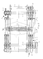
- the Shed forming device a frame 1, the two in the distance and frame plates 2, 3 and two arranged parallel to one another Has axes 4.5, which rotatably with the shields are connected.
- Two shafts 10 are rotatably mounted in frame 1, which protrude beyond the frame plates 2,3. On each Each shaft 10 has a drive wheel 11 attached to it are connected to each other by a toothed belt 12. On one of the shafts 10 has a second drive wheel 13 attached, that via a further toothed belt 14 with a Main drive, not shown, is connected.
- crank mechanisms 15 for each pair of knife banks assigned, each a drive crank 16 and one connected connecting rod 17.
- the Crank gearboxes are a pair of knife banks 6.7 assigned and on both ends of each knife bench pair arranges the shaft 10, so that each pair of knife banks their ends are moved up and down synchronously.
- the crank mechanism 15 contains a drive crank 16 and a connecting rod 17.
- the treads of the Drive crank 16 for a pair of knives by 180 degrees opposite the treads of the drive crank for the other Pair of knives arranged offset to the opposite To achieve upward and downward movement.
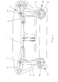
- Each knife bank 6,7 is at one end with a lever 18 and at the other end with a lever arrangement 19 and also connected to the connecting rod 17 of the crank mechanism.
- the connecting rod 17 and the lever 18 and the Lever arrangement 19 can be rotated by an adjusting screw 20 connected, which penetrates an elongated hole 21 and therein is adjustable by the swivel angle of each lever or each lever arrangement and thus the lifting height for each Knife bench pair 6.7 individually.
- the lifting height can be arranged at each end of the knife bench pair either the same to form a parallel subject, or unequal can be set to form a slant compartment.
- the lever 18 consists of two parallel ones Crosspieces 22 and two bushings 23, which the pivot axis of Determine lever 18.
- the lever 18 is on the one hand positionally stable axis 4 and on the other hand on the movable Knife bench articulated.
- the lever arrangement 19 contains one of the same type trained lever 24 with two webs 22 and two Bushings 23 and a handlebar 27.
- the lever 24 is on the one hand to the movable knife bench and on the other hand the pivotable handlebar 27 articulated.
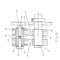
- the handlebar 27 is on the positionally stable axis 5 articulated. The occurring Displacement is absorbed by the handlebar 27.
- the maximum swing out of the handlebars is with dashed lines Lines shown.
- the handlebars 27 are each with a Liner 40 provided and by a spacer 41 from spaced apart on the fixed shaft 5 arranged as well as against 42 by moving secured. Is between the sleeve 23 and the handlebar 27 a bearing sleeve 43 is provided, which the webs 22nd keeps your distance at the same time.
- the liner 23 is on one end a flange 44 and an internal thread in one Screw 45 is screwed in. Be screw 45 by this the webs 22 attached to the liner 23.
- Each pair of knife banks 6,7 is a number of Lifting blades 8 assigned.
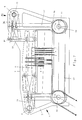
- FIGs 2 and 6 show are the individual lifting knife by means of holder 30 with the Knife bench connected.
- the lifting knife 8 is with the holder 30 firmly connected and the holder is hinged to the knife bank.
- Each lifting knife 8 is guided in a guide arrangement 31, so that the lifting knife 8 makes a straight up and down movement executes. This causes a deflection of the lifting knife 8 detectable boards (not shown) prevented.
- the Guide assembly 31 consists of a plate 32 which the outer sides of the frame plates 2,3 are attached. In of the plate 32 are slots 33 through which the lifting knife 8 extends and during the opening and Movement is performed.
- the lever assembly 35 includes a lever 36 and one Handlebar 37.
- the lever 36 consists of two parallel Crosspieces connected at the ends by means of bushings 40, 41 are which determine the pivot axis of the lever 36.
- the lever 36 is on the stable position Axle 5 articulated, while the handlebar 37 on the one hand to the pivotable lever 36 and on the other hand to the movable Knife bench is articulated.
Landscapes
- Engineering & Computer Science (AREA)
- Textile Engineering (AREA)
- Harvester Elements (AREA)
- Looms (AREA)
Description
- durch die Aufhängung der Messerbänke auf einer Seite an einem einzigen quer zur Bewegungsrichtung der Messerbank verlaufenden Hebel und die Hebelanordnung auf der anderen Seite wird eine lagestabile Führung erreicht und die sonst übliche Führung und damit eine wesentliche Verschleissquelle und ein wesentlicher Energieverbrauch vermieden, wodurch die Leistungsfähigkeit und Lebensdauer der Vorrichtung verbessert werden;
- die Vorrichtung eine für die Bewegung der Messerbank geringe Anzahl von Antriebselementen aufweist, also massenarm ist;
- die bei der Auf- und Abbewegung der Messerbank auftretende Verlagerung derselben selbst bei langen Hubmessern und/oder grossem Hub ausgeglichen wird; und
- die Vorrichtung also ohne die sonst übliche Führung auskommt, wodurch für hohe Geschwindigkeiten mit minimalster Schmierung bei geringer Lärm- und Wärmeentwicklung ein verschleissfreier Bewegungsablauf und ein sicheres Betriebsverhalten gewährleistet ist.
Claims (10)
- Fachbildevorrichtung für eine Webmaschine, mit einem Gestell (1), mit zwei gegenläufig auf- und abbewegbaren Messerbankpaaren (6,7), mit Hubmessern (8), die mit dem Messerbankpaar verbunden sind, mit Kurbelgetrieben (15) für jede Messerbank, die jeweils zu beiden enden der Messerbank angeordnet sind und mit einem Hebelsystem (18,19), welches Kurbelgetriebe (15) mit der Messerbank verbindet, um jede Messerbank auf und ab zu bewegen, dadurch gekennzeichnet, dass jede Messerbank (6,7) einerseits mit einem angetriebenen Hebel (18) und andererseits mit einer Hebelanordnung (19,35) verbunden ist, wobei der angetriebene Hebel (18) am Gestell (1) lagestabil und an der Messerbank angelenkt ist, und dass die Hebelanordnung (19,35) einen angetriebenen Hebel (24,36) und einen Lenker (27,37) aufweist, wobei der angetriebene Hebel (24,36) über den Lenker (27,37) mit dem Gestell (1) oder mit der Messerbank (6,7) verbunden ist.
- Vorrichtung nach Anspruch 1 dadurch gekennzeichnet, dass der Hebel (24) der Hebelanordnung (19) an die Messerbank angelenkt ist und dass der Lenker (27) einerseits an das Gestell (1) lagestabil angelenkt und andererseits mit dem Hebel (24) gelenkig verbunden ist.
- Vorrichtung nach Anspruch 1 dadurch gekennzeichnet, dass der Hebel (36) der Hebelanordnung (35) an das Gestell (1) lagestabil angelenkt ist und der Lenker (37) einerseits mit dem Hebel (36) und andererseits mit der Messerbank gegelenkig verbunden ist.
- Vorrichtung nach Anspruch 1 dadurch gekennzeichnet, dass die Kurbelgetriebe (15) paarweise einem Messerbankpaar (6,7) zugeordnet und zu beiden Enden jedes Messerbankpaares auf einer Welle (10) angeordnet sind, derart, dass jedes Messerbankpaar (6,7) an den Enden synchron auf und ab bewegbar ist.
- Vorrichtung nach Anspruche 4 dadurch gekennzeichnet, dass das Kurbelgetriebe (15) eine Antriebskurbel (16) und eine Pleuelstange (17) aufweist.
- Vorrichtung nach Anspruch 5 dadurch gekennzeichnet, dass der Hebel (18) bzw. die Hebelanordnung (19,35) über eine Stelleinrichtung (20,21) mit der Pleuelstange (17) verbunden sind, um den Schwenkwinkel einzustellen, derart, dass die Hubhöhe der Enden jedes Messerbankpaares (6,7) entweder gleich, um ein Parallelfach zu bilden oder ungleich einstellbar ist, um ein Schrägfach zu bilden.
- Vorrichtung nach einem der Ansprüche 1 bis 6 dadurch gekennzeichnet, dass das Hubmesser (8) mit einem Halter (30) fest verbunden ist, der an die Messerbank angelenkt ist.
- Vorrichtung nach Anspruch 7 dadurch gekennzeichnet, dass das Hubmesser (8) mindestens an den Enden in einer Führungsanordnung (31) geführt ist, die im Gestell (1) befestigt ist.
- Vorrichtung nach Anspruch 1 dadurch gekennzeichnet, dass ein Antriebsrad (11) auf jeder Welle (10) befestigt ist, das über ein kinematisches Organ (12) antriebsverbunden sind, um die Kurbelgetriebe (15) synchron anzutreiben.
- Webmaschine mit einer Vorrichtung nach einem der Ansprüche 1 bis 9.
Applications Claiming Priority (3)
| Application Number | Priority Date | Filing Date | Title |
|---|---|---|---|
| CH1257/93 | 1993-04-26 | ||
| CH125793 | 1993-04-26 | ||
| PCT/CH1994/000028 WO1994025654A1 (de) | 1993-04-26 | 1994-02-11 | Fachbildevorrichtung für eine webmaschine |
Publications (2)
| Publication Number | Publication Date |
|---|---|
| EP0647283A1 EP0647283A1 (de) | 1995-04-12 |
| EP0647283B1 true EP0647283B1 (de) | 1998-11-04 |
Family
ID=4206158
Family Applications (1)
| Application Number | Title | Priority Date | Filing Date |
|---|---|---|---|
| EP94905642A Expired - Lifetime EP0647283B1 (de) | 1993-04-26 | 1994-02-11 | Fachbildevorrichtung für eine webmaschine |
Country Status (7)
| Country | Link |
|---|---|
| US (1) | US5513676A (de) |
| EP (1) | EP0647283B1 (de) |
| JP (1) | JP3586466B2 (de) |
| CN (1) | CN1040674C (de) |
| DE (2) | DE9307391U1 (de) |
| ES (1) | ES2125434T3 (de) |
| WO (1) | WO1994025654A1 (de) |
Families Citing this family (17)
| Publication number | Priority date | Publication date | Assignee | Title |
|---|---|---|---|---|
| JPH08302536A (ja) * | 1995-05-08 | 1996-11-19 | Kayaba Ind Co Ltd | 経糸選択装置 |
| FR2736939B1 (fr) * | 1995-07-18 | 1997-09-05 | Staubli Sa Ets | Mecanique jacquard a actionnement par arbres coaxiaux |
| FR2757544B1 (fr) * | 1996-12-19 | 1999-03-05 | Staubli Lyon | Dispositif de formation de la foule, procede de montage et metier a tisser de type jacquard equipe d'un tel dispositif |
| GB9715480D0 (en) * | 1997-07-23 | 1997-10-01 | Bonas Machine Co | Drive mechanism for a griffe frame |
| BE1013564A3 (nl) * | 2000-06-16 | 2002-04-02 | Wiele Michel Van De Nv | Inrichting voor de rechtgeleiding van de messendraagbalken in een jacquardmachine. |
| RU2299935C2 (ru) * | 2002-05-10 | 2007-05-27 | Текстильма АГ | Бесшнуровое устройство управления нитями |
| FR2854642B1 (fr) * | 2003-05-06 | 2005-07-08 | Staubli Lyon | Dispositif de formation de la foule et metier a tisser du type jacquard equipe d'un tel dispositif |
| BRPI0416975B1 (pt) * | 2003-11-28 | 2014-12-23 | Textilma Ag | Dispositivo de controle de fio para uma máquina têxtil, especialmente para um dispositivo de formação de cala |
| BE1016559A4 (nl) * | 2005-03-21 | 2007-01-09 | Wiele Michel Van De Nv | Jacquardinrichting. |
| CN101423995B (zh) * | 2008-12-18 | 2012-10-03 | 宁波川一纺织设备有限公司 | 一种曲柄复动式高速电子提花机 |
| CN102080287B (zh) * | 2011-01-31 | 2012-08-22 | 宁波川一纺织设备有限公司 | 一种高速助力平衡电子提花机 |
| CN102505244A (zh) * | 2011-10-28 | 2012-06-20 | 吴江市金迪喷织厂 | 纺织机刀杆连接装置 |
| CN103255529A (zh) * | 2013-05-16 | 2013-08-21 | 湖州厉华妤婕联合纺织有限公司 | 一种提花机提刀传动机构用连杆 |
| CN103243444A (zh) * | 2013-05-16 | 2013-08-14 | 湖州厉华妤婕联合纺织有限公司 | 一种提花机的传动轴的连接装置 |
| CN103290588B (zh) * | 2013-06-05 | 2014-09-24 | 傅加龙 | 电脑提花机及其传动机构 |
| CN105113085B (zh) * | 2015-09-22 | 2017-02-01 | 吴江万工机电设备有限公司 | 一种应用在提花机提综机构的板状连杆 |
| CN105420896B (zh) * | 2015-12-04 | 2017-07-11 | 郭家成 | 大针数提花开口的传动机构 |
Family Cites Families (12)
| Publication number | Priority date | Publication date | Assignee | Title |
|---|---|---|---|---|
| CH111971A (de) * | 1924-11-11 | 1925-12-16 | Rueti Ag Maschf | Doppelhub-Jacquardmaschine. |
| DE899929C (de) * | 1951-12-08 | 1953-12-17 | Pieron Handelsgesellschaft | Schraegfach-Jacquardmaschine |
| CH433133A (de) * | 1961-09-30 | 1967-03-31 | Metallgesellschaft Ag | Verfahren zur Entfernung von Phosphaten aus Abwässern |
| FR1331682A (fr) * | 1962-07-16 | 1963-07-05 | Webstuhlbau Karl Marx Stadt | Mécanique jacquard à double lève à foule ouverte |
| CH402759A (it) * | 1962-12-15 | 1965-11-15 | Brevitex Ets Exploit | Ratiera adatta specialmente per telai veloci |
| GB986770A (en) * | 1963-01-26 | 1965-03-24 | Samuel Dracup & Sons Ltd | Improvements in or relating to jacquard mechanisms |
| GB2047755B (en) * | 1979-04-24 | 1983-03-30 | Bonas Machine Co | Loom heald control means |
| DE3037089A1 (de) * | 1980-10-01 | 1982-05-06 | Basf Ag, 6700 Ludwigshafen | Verfahren zur herstellung von methylformiat |
| DE3721932A1 (de) * | 1987-07-02 | 1989-01-19 | Grosse Webereimaschinen Gmbh | Doppelhub-offenfach-jacquardmaschine |
| BE1004308A3 (nl) * | 1989-07-17 | 1992-10-27 | Wiele Michel Van De Nv | Aandrijfsysteem voor de messenroosters van een dubbel-hef-opengaap jacquardmachine, en dergelijke jacquardmachines van een dergelijk aandrijfsysteem voorzien. |
| DE4027575C1 (en) * | 1990-08-31 | 1992-02-06 | Wolfgang 5600 Wuppertal De Herold | Skew shed for loom - has lifting knives to carry sinkers for controlling needles, permitting high working speed |
| FR2669650B1 (fr) * | 1990-11-27 | 1994-04-29 | Staubli Verdol | Mecanisme de commande des cadres d'un dispositif de formation de la foule. |
-
1993
- 1993-05-14 DE DE9307391U patent/DE9307391U1/de not_active Expired - Lifetime
-
1994
- 1994-02-11 JP JP52371594A patent/JP3586466B2/ja not_active Expired - Fee Related
- 1994-02-11 ES ES94905642T patent/ES2125434T3/es not_active Expired - Lifetime
- 1994-02-11 WO PCT/CH1994/000028 patent/WO1994025654A1/de not_active Ceased
- 1994-02-11 EP EP94905642A patent/EP0647283B1/de not_active Expired - Lifetime
- 1994-02-11 CN CN94190234A patent/CN1040674C/zh not_active Expired - Lifetime
- 1994-02-11 DE DE59407224T patent/DE59407224D1/de not_active Expired - Lifetime
- 1994-12-12 US US08/351,335 patent/US5513676A/en not_active Expired - Lifetime
Also Published As
| Publication number | Publication date |
|---|---|
| JPH07508321A (ja) | 1995-09-14 |
| JP3586466B2 (ja) | 2004-11-10 |
| DE9307391U1 (de) | 1993-09-30 |
| EP0647283A1 (de) | 1995-04-12 |
| CN1108033A (zh) | 1995-09-06 |
| DE59407224D1 (de) | 1998-12-10 |
| CN1040674C (zh) | 1998-11-11 |
| WO1994025654A1 (de) | 1994-11-10 |
| US5513676A (en) | 1996-05-07 |
| ES2125434T3 (es) | 1999-03-01 |
Similar Documents
| Publication | Publication Date | Title |
|---|---|---|
| DE2655583C2 (de) | Stichsäge | |
| EP1732840B1 (de) | Hebevorrichtung | |
| DE2609411C3 (de) | Vorrichtung zum Steuern der flexiblen Greiferbänder einer Webmaschine | |
| DE19521050C2 (de) | Kniehebel-Antriebsvorrichtung | |
| EP0647283A1 (de) | Fachbildevorrichtung für eine webmaschine | |
| EP0409139B1 (de) | System zum Antrieb der Messeranordnungen einer Doppelhub-Offenfachjacquardmaschine und ähnlicher Jacquardmaschinen, die mit einem ähnlichen Antriebssystem versehen sind | |
| EP0041136A1 (de) | Schwenkantrieb für schwenkbar gelagerte Maschinenteile, insbesondere bei Manipulatoren | |
| EP2008799A1 (de) | Stanzpresse | |
| DE2821650A1 (de) | Einrichtung zum ausbreiten von im strang behandelten geweben | |
| EP0395964A1 (de) | Vorrichtung für den Massenkraftausgleich in einer Maschine mit Kurbeltrieb, insbesondere einer Stanzmaschine | |
| DE69604137T2 (de) | Jacquardmaschine mit koaxialen Antriebswellen | |
| EP0823508A2 (de) | Pressenanordnung | |
| DE3828469C2 (de) | ||
| CH703090B1 (de) | Schiffchen-Stickmaschine mit Antrieb des Treiberbalkens. | |
| CH655147A5 (de) | Zwillingsstopfaggregat einer gleisbaumaschine. | |
| DE3226942A1 (de) | Schuettelmaschine | |
| DE69102716T3 (de) | Schaltmechanismus für die Bewegung des Greiferrahmens einer Fachbildungsvorrichtung. | |
| DE2531356C3 (de) | ||
| DE10355972A1 (de) | Schneidemaschine für Tafeln | |
| EP0272522A1 (de) | Kurbeltrieb, insbesondere für Hubkolbenmotoren | |
| EP0105246B1 (de) | Antriebs- und Führungsvorrichtung mit einem Hubzylinder und einem Übertragungselement | |
| DE2644489C3 (de) | Vorrichtung zum Bilden des Webfaches einer Wellenfach-Webmaschine | |
| EP0141258A2 (de) | Wickelapparat zum Bilden von Wattewickeln | |
| DE1936227C3 (de) | Doppelhub-Jacquardmaschine | |
| EP1172186B1 (de) | Vorrichtung zum Schneiden von blattförmigem Gut |
Legal Events
| Date | Code | Title | Description |
|---|---|---|---|
| PUAI | Public reference made under article 153(3) epc to a published international application that has entered the european phase |
Free format text: ORIGINAL CODE: 0009012 |
|
| 17P | Request for examination filed |
Effective date: 19941028 |
|
| AK | Designated contracting states |
Kind code of ref document: A1 Designated state(s): BE CH DE ES FR GB IT LI NL |
|
| GRAG | Despatch of communication of intention to grant |
Free format text: ORIGINAL CODE: EPIDOS AGRA |
|
| 17Q | First examination report despatched |
Effective date: 19960306 |
|
| GRAG | Despatch of communication of intention to grant |
Free format text: ORIGINAL CODE: EPIDOS AGRA |
|
| GRAG | Despatch of communication of intention to grant |
Free format text: ORIGINAL CODE: EPIDOS AGRA |
|
| GRAH | Despatch of communication of intention to grant a patent |
Free format text: ORIGINAL CODE: EPIDOS IGRA |
|
| GRAH | Despatch of communication of intention to grant a patent |
Free format text: ORIGINAL CODE: EPIDOS IGRA |
|
| GRAA | (expected) grant |
Free format text: ORIGINAL CODE: 0009210 |
|
| AK | Designated contracting states |
Kind code of ref document: B1 Designated state(s): BE CH DE ES FR GB IT LI NL |
|
| REG | Reference to a national code |
Ref country code: CH Ref legal event code: NV Representative=s name: SCHMAUDER & PARTNER AG PATENTANWALTSBUERO Ref country code: CH Ref legal event code: EP |
|
| REF | Corresponds to: |
Ref document number: 59407224 Country of ref document: DE Date of ref document: 19981210 |
|
| ITF | It: translation for a ep patent filed | ||
| ET | Fr: translation filed | ||
| REG | Reference to a national code |
Ref country code: ES Ref legal event code: FG2A Ref document number: 2125434 Country of ref document: ES Kind code of ref document: T3 |
|
| GBT | Gb: translation of ep patent filed (gb section 77(6)(a)/1977) |
Effective date: 19990208 |
|
| PLBE | No opposition filed within time limit |
Free format text: ORIGINAL CODE: 0009261 |
|
| STAA | Information on the status of an ep patent application or granted ep patent |
Free format text: STATUS: NO OPPOSITION FILED WITHIN TIME LIMIT |
|
| 26N | No opposition filed | ||
| REG | Reference to a national code |
Ref country code: GB Ref legal event code: IF02 |
|
| PGFP | Annual fee paid to national office [announced via postgrant information from national office to epo] |
Ref country code: ES Payment date: 20090219 Year of fee payment: 16 |
|
| PGFP | Annual fee paid to national office [announced via postgrant information from national office to epo] |
Ref country code: NL Payment date: 20090217 Year of fee payment: 16 |
|
| PGFP | Annual fee paid to national office [announced via postgrant information from national office to epo] |
Ref country code: GB Payment date: 20090219 Year of fee payment: 16 Ref country code: CH Payment date: 20090217 Year of fee payment: 16 |
|
| REG | Reference to a national code |
Ref country code: CH Ref legal event code: PCAR Free format text: SCHMAUDER & PARTNER AG PATENT- UND MARKENANWAELTE VSP;ZWAENGIWEG 7;8038 ZUERICH (CH) |
|
| REG | Reference to a national code |
Ref country code: NL Ref legal event code: V1 Effective date: 20100901 |
|
| REG | Reference to a national code |
Ref country code: CH Ref legal event code: PL |
|
| GBPC | Gb: european patent ceased through non-payment of renewal fee |
Effective date: 20100211 |
|
| PG25 | Lapsed in a contracting state [announced via postgrant information from national office to epo] |
Ref country code: LI Free format text: LAPSE BECAUSE OF NON-PAYMENT OF DUE FEES Effective date: 20100228 Ref country code: CH Free format text: LAPSE BECAUSE OF NON-PAYMENT OF DUE FEES Effective date: 20100228 |
|
| PG25 | Lapsed in a contracting state [announced via postgrant information from national office to epo] |
Ref country code: NL Free format text: LAPSE BECAUSE OF NON-PAYMENT OF DUE FEES Effective date: 20100901 |
|
| REG | Reference to a national code |
Ref country code: ES Ref legal event code: FD2A Effective date: 20110309 |
|
| PG25 | Lapsed in a contracting state [announced via postgrant information from national office to epo] |
Ref country code: GB Free format text: LAPSE BECAUSE OF NON-PAYMENT OF DUE FEES Effective date: 20100211 |
|
| PG25 | Lapsed in a contracting state [announced via postgrant information from national office to epo] |
Ref country code: ES Free format text: LAPSE BECAUSE OF NON-PAYMENT OF DUE FEES Effective date: 20110308 |
|
| PG25 | Lapsed in a contracting state [announced via postgrant information from national office to epo] |
Ref country code: ES Free format text: LAPSE BECAUSE OF NON-PAYMENT OF DUE FEES Effective date: 20100212 |
|
| PGFP | Annual fee paid to national office [announced via postgrant information from national office to epo] |
Ref country code: IT Payment date: 20120224 Year of fee payment: 19 |
|
| PGFP | Annual fee paid to national office [announced via postgrant information from national office to epo] |
Ref country code: FR Payment date: 20130301 Year of fee payment: 20 Ref country code: DE Payment date: 20130219 Year of fee payment: 20 |
|
| PGFP | Annual fee paid to national office [announced via postgrant information from national office to epo] |
Ref country code: BE Payment date: 20130220 Year of fee payment: 20 |
|
| REG | Reference to a national code |
Ref country code: DE Ref legal event code: R071 Ref document number: 59407224 Country of ref document: DE |
|
| REG | Reference to a national code |
Ref country code: DE Ref legal event code: R071 Ref document number: 59407224 Country of ref document: DE |
|
| BE20 | Be: patent expired |
Owner name: *TEXTILMA A.G. Effective date: 20140211 |
|
| PG25 | Lapsed in a contracting state [announced via postgrant information from national office to epo] |
Ref country code: DE Free format text: LAPSE BECAUSE OF EXPIRATION OF PROTECTION Effective date: 20140212 |