EP0647467B1 - Einheitlicher, einstückiger, drehbarer Mischer und Abgabekopf - Google Patents
Einheitlicher, einstückiger, drehbarer Mischer und Abgabekopf Download PDFInfo
- Publication number
- EP0647467B1 EP0647467B1 EP94115535A EP94115535A EP0647467B1 EP 0647467 B1 EP0647467 B1 EP 0647467B1 EP 94115535 A EP94115535 A EP 94115535A EP 94115535 A EP94115535 A EP 94115535A EP 0647467 B1 EP0647467 B1 EP 0647467B1
- Authority
- EP
- European Patent Office
- Prior art keywords
- mixing chamber
- impeller blades
- mixer
- rigidly connected
- disperser head
- Prior art date
- Legal status (The legal status is an assumption and is not a legal conclusion. Google has not performed a legal analysis and makes no representation as to the accuracy of the status listed.)
- Expired - Lifetime
Links
- 238000002156 mixing Methods 0.000 claims abstract description 72
- 238000003466 welding Methods 0.000 claims abstract description 11
- 239000000203 mixture Substances 0.000 claims description 14
- 239000012530 fluid Substances 0.000 claims description 13
- 238000007373 indentation Methods 0.000 claims description 7
- 230000002093 peripheral effect Effects 0.000 claims description 7
- 229910001220 stainless steel Inorganic materials 0.000 claims description 7
- 239000010935 stainless steel Substances 0.000 claims description 7
- 230000015572 biosynthetic process Effects 0.000 claims description 4
- 238000005755 formation reaction Methods 0.000 claims description 4
- 230000001154 acute effect Effects 0.000 claims description 3
- 239000007769 metal material Substances 0.000 claims description 3
- 239000000126 substance Substances 0.000 description 18
- 238000000034 method Methods 0.000 description 6
- 239000007788 liquid Substances 0.000 description 5
- 239000000463 material Substances 0.000 description 5
- 238000007689 inspection Methods 0.000 description 4
- 239000007787 solid Substances 0.000 description 4
- 230000014759 maintenance of location Effects 0.000 description 3
- 238000004026 adhesive bonding Methods 0.000 description 2
- 238000004140 cleaning Methods 0.000 description 2
- 238000010276 construction Methods 0.000 description 2
- 238000003801 milling Methods 0.000 description 2
- 238000005192 partition Methods 0.000 description 2
- 229920003023 plastic Polymers 0.000 description 2
- 239000004033 plastic Substances 0.000 description 2
- 238000005086 pumping Methods 0.000 description 2
- 238000004080 punching Methods 0.000 description 2
- 238000005452 bending Methods 0.000 description 1
- 230000001804 emulsifying effect Effects 0.000 description 1
- 239000007789 gas Substances 0.000 description 1
- 238000005304 joining Methods 0.000 description 1
- 239000002184 metal Substances 0.000 description 1
- 239000013618 particulate matter Substances 0.000 description 1
- 238000007514 turning Methods 0.000 description 1
Images


Classifications
-
- B—PERFORMING OPERATIONS; TRANSPORTING
- B01—PHYSICAL OR CHEMICAL PROCESSES OR APPARATUS IN GENERAL
- B01F—MIXING, e.g. DISSOLVING, EMULSIFYING OR DISPERSING
- B01F27/00—Mixers with rotary stirring devices in fixed receptacles; Kneaders
- B01F27/05—Stirrers
- B01F27/11—Stirrers characterised by the configuration of the stirrers
- B01F27/116—Stirrers shaped as cylinders, balls or rollers
-
- B—PERFORMING OPERATIONS; TRANSPORTING
- B01—PHYSICAL OR CHEMICAL PROCESSES OR APPARATUS IN GENERAL
- B01F—MIXING, e.g. DISSOLVING, EMULSIFYING OR DISPERSING
- B01F27/00—Mixers with rotary stirring devices in fixed receptacles; Kneaders
- B01F27/05—Stirrers
- B01F27/11—Stirrers characterised by the configuration of the stirrers
- B01F27/116—Stirrers shaped as cylinders, balls or rollers
- B01F27/1161—Stirrers shaped as cylinders, balls or rollers having holes in the surface
Definitions
- the present invention relates to a rotary mixer and disperser head for operations such as dispersing, dissolving, emulsifying and blending of solids, liquids or gases with other liquids.
- the mixer and disperser head according to the invention is particularly useful in the food-processing industry, the chemical industry, the pharmaceutical industry and other branches of industry for dispersing and dissolving of solids and semi-solids in liquids.
- a mixer head for such purposes is shown in Figs. 1 and 2 of US-A-3,170,638.
- This mixer head has a mixing chamber comprising two sections in the form of truncated cones; one at each end of a cylindrical middle section which is slotted along its periphery, and a central shaft extends through the mixer head.
- the conical sections act as centrifugal pumps pumping the substances to be mixed into the cylindrical section where in a first stage they undergo a hydraulic shear where the two streams meet.
- the slots in the middle section act in a second stage as specific shear elements, while a third shear stage occurs when the radial discharge from the head meet the slower moving contents of the mixing vessel.
- the shear forces act to mix the substances and in particular to disperse and dissolve solids in the fluid mixture.
- Mixer heads of this type present several disadvantages.
- the throughput is delimited by the smaller cross sectional inlet areas of the conical sections.
- the conical sections impart to the substances to be mixed a considerable tangential component of velocity which rather than to contribute to the hydraulic shear detracts therefrom.
- the central shaft extending through the mixing chamber reduces the volume thereof and thereby the retention time therein for the fluid mixture.
- mixer heads not immediately accessible for ocular inspection after a cleaning-in-place procedure (CIP-procedure) due to the presence of the conical sections and the throughgoing shaft.
- a mixer and disperser head is furthermore shown in Figs. 1-3 of US-A-4,900,159.
- this mixer head a pair of impellers are clamped to each end of a generally cylindrical mixing chamber by means of a shoulder and a nut on a shaft extending through a bore in a central hub in the mixing chamber.
- the mixing chamber has a plurality of axially extending slots in its peripheral wall which is connected to the central hub by means of a radial flange placed in the middle of the mixing chamber and as a partition separating that in two chambers.
- the central hub and the flange reduce the volume of the mixing chambers and thereby the retention time therein for the fluid mixture, and the same parts will likewise impart a rotational velocity to the substances to be mixed, i.e. a tangential component of velocity, which will detract from the shear imparted to the fluid mixture when discharged through the elongate slots.
- the flange or partition prevents that the two streams from the opposite ends of the mixing head meet and thereby undergo a hydraulic shear.
- This known mixer head is completely unsuited for a CIP-procedure partly because of the many unaccessible corners therein where particulate matter or substances with high viscosity or adhesiveness may accumulate and partly because of the impellers clamped flatly on to the ends of the cylindrical mixing chamber making an ocular inspection of the inner of the mixing head practically impossible.
- a thorough cleaning of this known mixer and disperser head necessitates a complete disassembling of the head, separate cleaning of each of its parts, and reassembling again thereof.
- the object of the present invention to provide a rotary mixer and disperser head which will avoid the aforesaid drawbacks and where the volume of the mixing chamber is not reduced by an axially extending shaft or hub and flange so that the mixing chamber presents the greatest possible volume relative to its outer dimensions, where the circular motion imparted to the substances to be mixed in the mixing chamber is kept as low as possible and the mechanical shear imparted thereto by the axially extending slots thereby kept as high as possible, where a high liquid shear in the substances is obtained in the mixing chamber when the two counter-directed in-flow streams meet therein having high axial velocities and a rotary mixer and disperser head which is particularly well-suited for the CIP-procedure and is easily inspected ocularly after such procedure.
- the mixer and disperser head according to the invention should be manufactured as a high-quality integral one-piece product by simple and inexpensive technological methods.
- a rotary mixer and disperser head comprising:
- the shaft is disposed entirely outside the mixing chamber and only rigidly connected to the radially inner ends of the first plurality of impeller blades. Due to the absence of the shaft from the mixing chamber this has a maximum volume providing for an optimum retention time for the fluid medium therein and the shaft can of course not impart any rotational movement to that medium.
- the particular design of the impeller blades impart to the in-flow from each end of the mixing chamber an inwardly directed thrust and a high velocity having a pre-dominating axial component thereby creating an intense hydraulic shear in the fluid mixture while at the same time imparting a high mechanical shear thereto.
- This particular design also allows for an ocular inspection of the inner parts of the mixer and disperser head, and the integral one-piece construction thereof leaves no corners wherein polluting matter may accumulate so that the inventive mixer and disperser head is well-suited for a CIP-procedure.
- the different parts of the mixer and disperser head may readily be manufactured from stock materials such as tubing and sheet materials by simple technological processes such as turning, milling, punching and stamping and assembled by joining processes such as welding or adhesive bonding.
- At least some of said first and second pluralities of impeller blades have formations for creating turbulence or shear in a fluid mixture passing thereover. This further adds to the shear forces mechanically imparted to the fluid mixture by the impeller blades.
- the said formations may preferably be indentations at the trailing edges of said impeller blades, and said indentations have more preferably a generally castellation-like profile.
- each of said plurality of elongated slots through the peripheral wall of said mixing chamber forms an acute angle with the tangent to the inside of said wall at the point of intersection. This feature adds further to the shear forces introduced in the fluid mixture as it leaves the inventive mixer and disperser head.
- the various parts of the mixer and disperser head of the invention are made from a metallic material such as stainless steel and rigidly connected to each other by means of welding so as to form an integral one-piece unit.
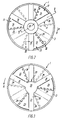
- Figs. 1, 2 and 3 1 generally indicates a rotary mixer and disperser head according to the invention.
- the mixer and disperser head 1 comprises a tubular mixing chamber 3 preferably made of stainless steel and having a circular cross section and a central axis 5. Spaced equally angularly are through the wall of mixing chamber 3 in the axially middle region thereof provided a plurality of axially extending elongated discharge slots 7.
- a first set of impeller blades preferably made of stainless steel and generally indicated as 11, and connected to the first set of impeller blades 11 by welding such as at 13 is a shaft 15 also preferably of stainless steel and situated above the first set of impeller blades 11 and coaxial with the mixing chamber 3.
- the first set of impeller blades 11 comprises three identical impeller blades 17 (see Fig. 2) disposed angularly offset by 120° for each other around the central axis 5.
- Each of the impeller blades 17 comprises a leading portion 19 (leading in the direction of rotation "R" of the mixer and disperser head 1) and a trailing portion 21.
- the leading portion 19 of each of the impeller blades 17 has a first part 23 extending in a plane perpendicular to the axis 5, and a second part 24 bent inward about 90° from the first part 23 and connected by welding such as at 9 to the upper rim of the mixing chamber 3.
- the radially inner end of the first part 23 is connected to the shaft 15 by means of welding such as at 13.
- the trailing portion 21 forms as best seen in Fig. 4 an obtuse inward angle with the first part 23 of the leading portion 19 and has in a plane projection the shape of a sector of an annulus. Its trailing edge has indentations with a castellation-like profile 25.
- a second set of impeller blades preferably made of stainless steel and generally indicated as 27.
- the second set of impeller blades 27 is a mirror image of the first set of impeller blades 11 and is offset relative thereto by 60° in the direction "R" of rotation of the mixer and disperser head 1.
- This second set of impeller blades 27 will therefore only be described in outlines in the following since more detailed information thereon may be had from the foregoing description of the first set of impeller blades 11 in connection with Figs. 2, 4 and 5.
- the second set of impeller blades 27 comprises three identical impeller blades 29 angularly offset by 120° for each other about the central axis 5.
- Each impeller blade 29 comprises a leading portion 31 and a trailing portion 33.
- the leading portion 31 has a radially inner first part 35 extending in a plane perpendicular to the axis 5 and a radially outer second part 36 bent about 90° inward from the first part 35.
- the radially inner parts 35 of the three impeller blades 29 are joined in a hub-like central disc 37, and the free ends of the bent parts 36 are connected so as by welding to the lower rim of the mixing chamber 3.
- each impeller blade 29 forms an obtuse inward angle with the first part 35 of the leading portion 31 and has in a plane projection the shape of a sector of an annulus. Its trailing edge has indentations with a castellation-like profile 39.
- first and second sets of impeller blades 11 and 27, respectively may be made from flat sheet metal by punching using the same set of dies, and by bending such as by stamping trailing portions 21 and bent parts 24 to one side to obtain a set of impeller blades 11 and trailing portions 33 and bent parts 36 to the opposite side to obtain a set of impeller blades 27.
- the slots 7 through the peripheral wall of mixing chamber 3 are not made as generally radial extending slots through said wall but are made such as by milling so that the middle plane through slot 7 forms an angle with a radial plane and more particularly so that the trailing edge of slot 7 forms an acute angle with the tangent to the inside surface of the wall at the point of intersection.
- this feature contributes to the shear forces introduced into the fluid mixture expelled through slots 7.
- the trailing edges of slots 7 so formed also enchance the centrifugal pumping action of the mixing chamber 3 by increasing the velocity by which the fluid mixture is expelled from the mixing chamber into the liquid mixture in the surrounding vessel thereby also increasing the hydraulic shear obtained thereby.
- the shaft 15 has a central bore 40 therein provided with an internal thread 41 adapted to be threadingly engaged with a corresponding external thread on a drive shaft (not shown) connected to a drive unit such as an electric motor or a hydraulic or pneumatic motor for rotatably driving the mixer and disperser head 1.
- a drive unit such as an electric motor or a hydraulic or pneumatic motor for rotatably driving the mixer and disperser head 1.
- the said substances firstly undergo an abrupt change of relative direction of movement resulting in the introduction of accelerative shear forces therein, secondly the flowing substances are further split up by the castellation-like indentations 25 and 39, respectively, introducing further turbulence and shear therein.
- Within the mixing chamber 3 the two streams of substances collide substantially axially at high velocities creating a high hydraulic shear. Due to the absence of a high speed rotating shaft or hub and flange there is no rotative force in the central parts of the mixing chamber acting upon the substances.
- the greater part of the substances move toward the periphery in a mainly non-rotative, radial direction whereby - during the expellation of the substances through the discharge slots - the high speed rotating slots act upon the slower moving substances with high mechanical shear.
- the substances are expelled therefrom with high velocity into the surrounding mixture, whereby they undergo further high hydraulic shear.
- the inventive mixer and disperser head lends itself to an ocular inspection after a CIP-procedure.
- the discharge openings may have any other appropriate shape than that of axially extending elongated slots, and also the impeller blades may be present in another number than three for each set of impeller blades and may have another shape than that described.
- the mixer and disperser head it may also be made from other materials than stainless steel, e.g. from plastics materials, or from a combination of plastics materials and metallic materials, and the various parts of the mixer and disperser head may be rigidly connected to each other by other means than welding, e.g. by adhesive bonding.
Landscapes
- Chemical & Material Sciences (AREA)
- Chemical Kinetics & Catalysis (AREA)
- Mixers Of The Rotary Stirring Type (AREA)
- Food-Manufacturing Devices (AREA)
Claims (6)
- Rotierender Misch- und Dispergierkopf (1), umfassend:- eine zum Verbinden mit einer drehbaren Antriebswelle angepaßte Welle (15),- eine zu der besagten Welle (15) koaxiale und starr mit dieser verbundene Mischkammer (3), wobei die besagte Mischkammer (3) von einer allgemein zylindrischen Gestalt ist und durch ihre Umfangswand hindurch eine Mehrzahl von Austragsöffnungen aufweist, insbesondere in einer allgemein axialen Richtung der Kammer (3) verlaufende, in gleichen Winkelabständen angeordnete langgestreckte Schlitze (7),- eine erste Mehrzahl (17) von in gleichen Winkelabständen angeordneten Rührflügeln (11) an einem axialen Ende der besagten Mischkammer (3), wobei jeder der besagten Mehrzahl von Rührflügeln (11) einen axial außerhalb des besagten einen axialen Endes angeordneten vorderen Rand und einen von dem besagten vorderen Rand aus zur Mischkammer (3) hin axial nach innen zu angeordneten hinteren Rand aufweist, und- eine zweite Mehrzahl von in gleichen Winkelabständen angeordneten Rührflügeln (27) am anderen axialen Ende der besagten Mischkammer (3), wobei jeder der besagten zweiten Mehrzahl von Rührflügeln (27) einen axial außerhalb des besagten anderen axialen Endes angeordneten vorderen Rand und einen von dem besagten vorderen Rand aus zur Mischkammer (3) hin axial nach innen zu angeordneten hinteren Rand aufweist,
wobei jeder der besagten ersten Mehrzahl (17) von Rührflügeln (11) umfaßt: einen vorderen Teil (19) mit einem ersten Teilstück (23), das sich in einer zur Achse (5) der Mischkammer (3) im wesentlichen senkrechten Ebene erstreckt, wobei das radial innere Ende des ersten Teilstücks (23) starr mit der besagten Welle (15) verbunden ist, welche sich völlig außerhalb der Mischkammer (3) befindet, und einem zweiten Teilstück (24), das von dem besagten ersten Teilstück (23) aus um etwa 90° nach innen zur Mischkammer (3) hin umgebogen und mit seinem freien Ende im Abstand von der besagten Ebene (bei 9) starr mit dem besagten einen axialen Ende der Mischkammer (3) verbunden ist, sowie einen hinteren Teil (21), der als Einheit mit dem ersten Teilstück (23) des besagten vorderen Teils (19) ausgebildet ist und mit diesem einen stumpfen Winkel einschließt und in einer Ebenenprojektion die Form eines Sektors eines Kreisrings aufweist,
und wobei jeder der besagten zweiten Mehrzahl von Rührflügeln (27) umfaßt: einen vorderen Teil (31) mit einem ersten Teilstück (35), das außerhalb der Mischkammer (3) angeordnet ist und sich in einer zur Achse (5) der Mischkammer (3) im wesentlich senkrechten Ebene erstreckt, wobei das radial innere Ende des ersten Teilstücks (35) mit den entsprechenden inneren Enden der anderen Rührflügel (29) der besagten zweiten Mehrzahl von Rührflügeln (27) verbunden ist, und einem zweiten Teilstück (36), das von dem besagten ersten Teilstück (35) aus um etwa 90° nach innen zur Mischkammer hin umgebogen ist und mit seinem freien Ende im Abstand von der besagten Ebene starr mit dem besagten anderen axialen Ende der Mischkammer (3) verbunden ist, sowie einen hinteren Teil (33), der als Einheit mit dem ersten Teilstück (35) des besagten vorderen Teils (31) ausgebildet ist und mit diesem einen stumpfen Winkel einschließt und in einer Ebenenprojektion die Form eines Sektors eines Kreisrings aufweist, wobei jeder der hinteren Teile (21,33) der ersten (17) und zweiten (27) Mehrzahl von Rührflügeln (11) vom vorderen Teil (19,31) aus in die Mischkammer (3) hineingeführt ist und in Drehrichtung des Mischers hinter dem vorderen Teil (19,31) angeordnet ist. - Misch- und Dispergierkopf (1) nach Anspruch 1, dadurch gekennzeichnet, daß mindestens einige der besagten ersten und zweiten Mehrzahl von Rührflügeln (17,27) Gebilde (25,39) zum Erzeugen einer Turbulenz oder Scherbeanspruchung in einem darüber hinwegtretenden flüssigen Gemisch aufweist.
- Misch- und Dispergierkopf nach Anspruch 2, dadurch gekennzeichnet, daß die besagten Gebilde Einschnitte (25,39) am hinteren Ende der besagten Rührflügel (11,29) sind.
- Misch- und Dispergierkopf nach Anspruch 3, dadurch gekennzeichnet, daß die besagten Einschnitte (25,39) ein allgemein zinnenartiges Profil aufweisen.
- Misch- und Dispergierkopf nach Anspruch 1, dadurch gekennzeichnet, daß der hintere Rand von jedem der besagten Mehrzahl von langgestreckten Schlitzen (7) durch die Umfangswand der besagten Mischkammer (3) mit der Tangente zur Innenseite der besagten Wand am Schnittpunkt einen spitzen Winkel (α) einschließt.
- Misch- und Dispergierkopf nach Anspruch 1, dadurch gekennzeichnet, daß die verschiedenen Teile aus einem metallischen Material, wie beispielsweise nichtrostendem Stahl hergestellt und durch Schweißen starr miteinander verbunden sind, so daß sie eine integrierte einstückige Einheit bilden.
Applications Claiming Priority (2)
| Application Number | Priority Date | Filing Date | Title |
|---|---|---|---|
| US133745 | 1993-10-07 | ||
| US08/133,745 US5407271A (en) | 1993-10-07 | 1993-10-07 | Integrated rotary mixer and disperser head |
Publications (2)
| Publication Number | Publication Date |
|---|---|
| EP0647467A1 EP0647467A1 (de) | 1995-04-12 |
| EP0647467B1 true EP0647467B1 (de) | 1997-01-08 |
Family
ID=22460112
Family Applications (1)
| Application Number | Title | Priority Date | Filing Date |
|---|---|---|---|
| EP94115535A Expired - Lifetime EP0647467B1 (de) | 1993-10-07 | 1994-10-03 | Einheitlicher, einstückiger, drehbarer Mischer und Abgabekopf |
Country Status (6)
| Country | Link |
|---|---|
| US (1) | US5407271A (de) |
| EP (1) | EP0647467B1 (de) |
| AT (1) | ATE147282T1 (de) |
| DE (1) | DE69401414T2 (de) |
| DK (1) | DK0647467T3 (de) |
| ES (1) | ES2100011T3 (de) |
Families Citing this family (11)
| Publication number | Priority date | Publication date | Assignee | Title |
|---|---|---|---|---|
| US7513678B2 (en) * | 2003-07-10 | 2009-04-07 | Venus Donald W | Rotary mixing device in molded packaging |
| WO2005105311A1 (en) * | 2004-04-26 | 2005-11-10 | Emerson Electric Co. | Food waste disposer shredder assembly |
| WO2014001436A1 (en) | 2012-06-29 | 2014-01-03 | Nestec S.A. | Double-cone pumping device |
| TW201446836A (zh) | 2013-05-01 | 2014-12-16 | Invista Tech Sarl | 用於製備部分平衡之酸性溶液之方法 |
| ES2696625T3 (es) * | 2013-07-03 | 2019-01-17 | Admix Inc | Cabezal mezclador rotatorio y dispersor integrado |
| TW201529640A (zh) | 2013-12-17 | 2015-08-01 | Invista Tech Sarl | 以具有分散器桿頭之容器製造供生產尼龍鹽之部分平衡酸溶液之方法 |
| CN105170293B (zh) * | 2015-09-29 | 2023-11-24 | 深圳市科力纳米工程设备有限公司 | 强制分散装置 |
| SE1650756A1 (en) * | 2016-05-31 | 2017-11-28 | Valmet Oy | Mixing unit comprising at least one rotor arm with recesses and a mixing apparatus comprising such a mixing unit |
| US10029222B2 (en) * | 2016-06-23 | 2018-07-24 | Dajustco Ip Holdings Inc. | Agitator having shrouded vanes for submersible pumps |
| CN107495839A (zh) * | 2017-08-10 | 2017-12-22 | 深圳西诺咖啡机制造有限公司 | 一种将水和二氧化碳即时混合生成碳酸水的装置 |
| CN119403454A (zh) * | 2022-05-13 | 2025-02-07 | 尚科宁家运营有限公司 | 用于碳酸化系统的搅拌器 |
Family Cites Families (11)
| Publication number | Priority date | Publication date | Assignee | Title |
|---|---|---|---|---|
| US2193686A (en) * | 1938-10-24 | 1940-03-12 | Frederick L Craddock | Mixing apparatus |
| US2461720A (en) * | 1944-07-29 | 1949-02-15 | Patterson Foundry & Machine Co | Mixing apparatus |
| GB664464A (en) * | 1949-08-29 | 1952-01-09 | Frederick John Edwin China | Improvements in and relating to mixers |
| US3170638A (en) * | 1963-04-12 | 1965-02-23 | Linwood P Burton | Mixing and disintegrating head |
| DE1281402B (de) * | 1963-10-24 | 1968-10-24 | Willy Suhner | Ruehrvorrichtung |
| US3290016A (en) * | 1965-01-08 | 1966-12-06 | Nettco Corp | Mixer means and impeller therefor |
| JPS55147141A (en) * | 1979-05-06 | 1980-11-15 | Yoshio Okaji | Cylinder type stirring blade |
| JPS5919526A (ja) * | 1982-07-23 | 1984-02-01 | Satake Kagaku Kikai Kogyo Kk | 撹拌機における撹拌翼 |
| US4490049A (en) * | 1983-06-02 | 1984-12-25 | Cron Chemical Corporation | Mixing arrangement |
| US4515482A (en) * | 1983-08-11 | 1985-05-07 | The Upjohn Company | Sterile suspension and solution holding and mixing tank |
| US4900159A (en) * | 1987-09-17 | 1990-02-13 | Nl Industries | High shear mixing apparatus |
-
1993
- 1993-10-07 US US08/133,745 patent/US5407271A/en not_active Expired - Lifetime
-
1994
- 1994-10-03 ES ES94115535T patent/ES2100011T3/es not_active Expired - Lifetime
- 1994-10-03 EP EP94115535A patent/EP0647467B1/de not_active Expired - Lifetime
- 1994-10-03 DK DK94115535.0T patent/DK0647467T3/da active
- 1994-10-03 DE DE69401414T patent/DE69401414T2/de not_active Expired - Lifetime
- 1994-10-03 AT AT94115535T patent/ATE147282T1/de active
Also Published As
| Publication number | Publication date |
|---|---|
| ATE147282T1 (de) | 1997-01-15 |
| DE69401414D1 (de) | 1997-02-20 |
| DE69401414T2 (de) | 1997-05-15 |
| EP0647467A1 (de) | 1995-04-12 |
| DK0647467T3 (da) | 1997-06-16 |
| US5407271A (en) | 1995-04-18 |
| ES2100011T3 (es) | 1997-06-01 |
Similar Documents
| Publication | Publication Date | Title |
|---|---|---|
| US5378321A (en) | Varying annular fluidization zone for increased mixing efficiency in a medium consistency mixer | |
| US6000840A (en) | Rotors and stators for mixers and emulsifiers | |
| US4900159A (en) | High shear mixing apparatus | |
| EP0651673B1 (de) | Scheibenförmiges rührgerät | |
| EP1331988B1 (de) | Dynamischer mischer | |
| US6568844B1 (en) | Device for in-vessel treatment | |
| CN103958041B (zh) | 具有槽形叶片的搅拌叶轮 | |
| US5246289A (en) | Agitator having streamlined blades for reduced cavitation | |
| EP0647467A1 (de) | Einheitlicher, einstückiger, drehbarer Mischer und Abgabekopf | |
| US4451155A (en) | Mixing device | |
| WO1996023977A1 (en) | A continuous dynamic mixing system and methods for operating such system | |
| EP1478454B1 (de) | Zweirichtungenmischrotor und verfahren | |
| EP1261417A2 (de) | Mischer mit rotierenden scheiben | |
| US9782734B2 (en) | Integrated rotary mixer and disperser head | |
| US4197019A (en) | Dual drive co-axial disperser | |
| US5797728A (en) | Disk-shaped impeller for mixing fluids | |
| JPS6271521A (ja) | 低速撹拌方法及びその装置 | |
| JP6610995B2 (ja) | 撹拌用回転体および撹拌装置 | |
| US3499633A (en) | Mixing device | |
| JPH0871396A (ja) | 撹拌翼 | |
| SU1473824A1 (ru) | Смеситель | |
| JP2022185524A (ja) | 攪拌部品及びこれを備える攪拌翼 | |
| CS237504B1 (cs) | Axiální míchadlo pro homogenizační míchání vícefázové kapalné směsi v chemických a biochemických reaktorech |
Legal Events
| Date | Code | Title | Description |
|---|---|---|---|
| PUAI | Public reference made under article 153(3) epc to a published international application that has entered the european phase |
Free format text: ORIGINAL CODE: 0009012 |
|
| AK | Designated contracting states |
Kind code of ref document: A1 Designated state(s): AT CH DE DK ES FR GB LI NL PT SE |
|
| 17P | Request for examination filed |
Effective date: 19951012 |
|
| GRAG | Despatch of communication of intention to grant |
Free format text: ORIGINAL CODE: EPIDOS AGRA |
|
| 17Q | First examination report despatched |
Effective date: 19960426 |
|
| GRAH | Despatch of communication of intention to grant a patent |
Free format text: ORIGINAL CODE: EPIDOS IGRA |
|
| GRAH | Despatch of communication of intention to grant a patent |
Free format text: ORIGINAL CODE: EPIDOS IGRA |
|
| GRAA | (expected) grant |
Free format text: ORIGINAL CODE: 0009210 |
|
| RIN1 | Information on inventor provided before grant (corrected) |
Inventor name: JENSEN, KNUD ERIK JUHL Inventor name: JORGENSEN, POVL JORGEN |
|
| AK | Designated contracting states |
Kind code of ref document: B1 Designated state(s): AT CH DE DK ES FR GB LI NL PT SE |
|
| PG25 | Lapsed in a contracting state [announced via postgrant information from national office to epo] |
Ref country code: LI Effective date: 19970108 Ref country code: CH Effective date: 19970108 Ref country code: AT Effective date: 19970108 |
|
| REF | Corresponds to: |
Ref document number: 147282 Country of ref document: AT Date of ref document: 19970115 Kind code of ref document: T |
|
| REG | Reference to a national code |
Ref country code: CH Ref legal event code: EP |
|
| REF | Corresponds to: |
Ref document number: 69401414 Country of ref document: DE Date of ref document: 19970220 |
|
| ET | Fr: translation filed | ||
| PG25 | Lapsed in a contracting state [announced via postgrant information from national office to epo] |
Ref country code: SE Effective date: 19970408 Ref country code: PT Effective date: 19970408 |
|
| REG | Reference to a national code |
Ref country code: ES Ref legal event code: FG2A Ref document number: 2100011 Country of ref document: ES Kind code of ref document: T3 |
|
| REG | Reference to a national code |
Ref country code: DK Ref legal event code: T3 |
|
| REG | Reference to a national code |
Ref country code: CH Ref legal event code: PL |
|
| PLBE | No opposition filed within time limit |
Free format text: ORIGINAL CODE: 0009261 |
|
| STAA | Information on the status of an ep patent application or granted ep patent |
Free format text: STATUS: NO OPPOSITION FILED WITHIN TIME LIMIT |
|
| 26N | No opposition filed | ||
| REG | Reference to a national code |
Ref country code: GB Ref legal event code: IF02 |
|
| PGFP | Annual fee paid to national office [announced via postgrant information from national office to epo] |
Ref country code: ES Payment date: 20110916 Year of fee payment: 18 Ref country code: FR Payment date: 20110914 Year of fee payment: 18 |
|
| PGFP | Annual fee paid to national office [announced via postgrant information from national office to epo] |
Ref country code: NL Payment date: 20110907 Year of fee payment: 18 |
|
| PGFP | Annual fee paid to national office [announced via postgrant information from national office to epo] |
Ref country code: GB Payment date: 20120928 Year of fee payment: 19 |
|
| PGFP | Annual fee paid to national office [announced via postgrant information from national office to epo] |
Ref country code: DK Payment date: 20121005 Year of fee payment: 19 |
|
| PGFP | Annual fee paid to national office [announced via postgrant information from national office to epo] |
Ref country code: DE Payment date: 20121031 Year of fee payment: 19 |
|
| REG | Reference to a national code |
Ref country code: NL Ref legal event code: V1 Effective date: 20130501 |
|
| REG | Reference to a national code |
Ref country code: FR Ref legal event code: ST Effective date: 20130628 |
|
| PG25 | Lapsed in a contracting state [announced via postgrant information from national office to epo] |
Ref country code: NL Free format text: LAPSE BECAUSE OF NON-PAYMENT OF DUE FEES Effective date: 20130501 Ref country code: FR Free format text: LAPSE BECAUSE OF NON-PAYMENT OF DUE FEES Effective date: 20121031 |
|
| REG | Reference to a national code |
Ref country code: ES Ref legal event code: FD2A Effective date: 20140116 |
|
| REG | Reference to a national code |
Ref country code: DK Ref legal event code: EBP Effective date: 20131031 |
|
| PG25 | Lapsed in a contracting state [announced via postgrant information from national office to epo] |
Ref country code: ES Free format text: LAPSE BECAUSE OF NON-PAYMENT OF DUE FEES Effective date: 20121004 |
|
| GBPC | Gb: european patent ceased through non-payment of renewal fee |
Effective date: 20131003 |
|
| REG | Reference to a national code |
Ref country code: DE Ref legal event code: R119 Ref document number: 69401414 Country of ref document: DE Effective date: 20140501 |
|
| PG25 | Lapsed in a contracting state [announced via postgrant information from national office to epo] |
Ref country code: GB Free format text: LAPSE BECAUSE OF NON-PAYMENT OF DUE FEES Effective date: 20131003 |
|
| PG25 | Lapsed in a contracting state [announced via postgrant information from national office to epo] |
Ref country code: DE Free format text: LAPSE BECAUSE OF NON-PAYMENT OF DUE FEES Effective date: 20140501 |
|
| PG25 | Lapsed in a contracting state [announced via postgrant information from national office to epo] |
Ref country code: DK Free format text: LAPSE BECAUSE OF NON-PAYMENT OF DUE FEES Effective date: 20131031 |