EP1478454B1 - Zweirichtungenmischrotor und verfahren - Google Patents
Zweirichtungenmischrotor und verfahren Download PDFInfo
- Publication number
- EP1478454B1 EP1478454B1 EP03711237A EP03711237A EP1478454B1 EP 1478454 B1 EP1478454 B1 EP 1478454B1 EP 03711237 A EP03711237 A EP 03711237A EP 03711237 A EP03711237 A EP 03711237A EP 1478454 B1 EP1478454 B1 EP 1478454B1
- Authority
- EP
- European Patent Office
- Prior art keywords
- impeller
- blade portion
- blade
- flow
- inner blade
- Prior art date
- Legal status (The legal status is an assumption and is not a legal conclusion. Google has not performed a legal analysis and makes no representation as to the accuracy of the status listed.)
- Expired - Lifetime
Links
- 230000009977 dual effect Effects 0.000 title description 10
- 239000000463 material Substances 0.000 description 32
- 230000008901 benefit Effects 0.000 description 7
- 230000000694 effects Effects 0.000 description 7
- 239000012530 fluid Substances 0.000 description 5
- 230000033001 locomotion Effects 0.000 description 3
- 238000004519 manufacturing process Methods 0.000 description 2
- 238000005086 pumping Methods 0.000 description 2
- 230000001052 transient effect Effects 0.000 description 2
- 230000002411 adverse Effects 0.000 description 1
- 230000009286 beneficial effect Effects 0.000 description 1
- 230000005540 biological transmission Effects 0.000 description 1
- 210000004027 cell Anatomy 0.000 description 1
- 239000013078 crystal Substances 0.000 description 1
- 238000010586 diagram Methods 0.000 description 1
- 238000000855 fermentation Methods 0.000 description 1
- 230000004151 fermentation Effects 0.000 description 1
- 230000001939 inductive effect Effects 0.000 description 1
- 239000007788 liquid Substances 0.000 description 1
- 210000004962 mammalian cell Anatomy 0.000 description 1
- 229920000642 polymer Polymers 0.000 description 1
- 239000002002 slurry Substances 0.000 description 1
- 239000007787 solid Substances 0.000 description 1
- 239000013598 vector Substances 0.000 description 1
Images

Classifications
-
- B—PERFORMING OPERATIONS; TRANSPORTING
- B01—PHYSICAL OR CHEMICAL PROCESSES OR APPARATUS IN GENERAL
- B01F—MIXING, e.g. DISSOLVING, EMULSIFYING OR DISPERSING
- B01F27/00—Mixers with rotary stirring devices in fixed receptacles; Kneaders
- B01F27/05—Stirrers
- B01F27/07—Stirrers characterised by their mounting on the shaft
- B01F27/072—Stirrers characterised by their mounting on the shaft characterised by the disposition of the stirrers with respect to the rotating axis
- B01F27/0726—Stirrers characterised by their mounting on the shaft characterised by the disposition of the stirrers with respect to the rotating axis having stirring elements connected to the stirrer shaft each by a single radial rod, other than open frameworks
-
- B—PERFORMING OPERATIONS; TRANSPORTING
- B01—PHYSICAL OR CHEMICAL PROCESSES OR APPARATUS IN GENERAL
- B01F—MIXING, e.g. DISSOLVING, EMULSIFYING OR DISPERSING
- B01F27/00—Mixers with rotary stirring devices in fixed receptacles; Kneaders
- B01F27/80—Mixers with rotary stirring devices in fixed receptacles; Kneaders with stirrers rotating about a substantially vertical axis
- B01F27/90—Mixers with rotary stirring devices in fixed receptacles; Kneaders with stirrers rotating about a substantially vertical axis with paddles or arms
Definitions
- the present invention relates to a rotating impeller for use in mixing vessels. More particularly, the invention pertains to a dual direction, counter flow, impeller that produces flow in two opposite directions.
- a mixing vessel that contains a material to be mixed.
- a rotating shaft extends into the vessel and rotates one or more generally radially extending impellers in order to cause flow in the material to mix the material.
- Such mixers are used in many industrial and manufacturing applications, including some applications for mixing medium to high viscosity materials. For these materials it is often necessary to perform the mixing in a laminar or transient flow environment. It is desirable to effect a proper mixing, while reducing the amount of energy that needs to be imparted to the material. Reducing the amount of energy imported helps to reduce the mechanical stresses on the impeller, the impeller shaft, and the drive system. Reducing the input energy applied to the material in the regions of the blades can also reduce the shear forces or other undesirable effects that can occur on shear sensitive materials when they are subjected to high shear forces.
- a radial impeller that has a blade angled in one direction.
- the blade extends less than the full radial distance from the shaft to the outside of the tank and pumps the material in one direction, for example, downwardly.
- Two sets of impeller blades may be disposed at different axial heights on the shaft. This arrangement will push the material in the downward direction in the area radially near the shaft and defined generally by the radial length of the blade.
- the material then flows horizontally outward at the lower part of the vessel and flows generally upward in a radial area generally between the blade tips of the vessel wall. Upon reaching near the top of the vessel, the material flow radially inwardly and then is pumped downward again by the blades.
- a disadvantage of this one-directional blade arrangement is that the energy required for the complete flow cycle is to be applied during only less than half of the flow cycle. In some situations, particularly, for medium and high viscosity materials, this can cause undesirable turbulent flow near the blades, and/or shear effects on the material, and incomplete vessel motion.
- Another approach to this problem has been to provide a so-called dual direction impeller which has a first radial segment that pumps fluid in one direction, (e.g., downwardly). Attached at the end of the first segment is a second segment oriented in the other direction that pumps fluid in the other direction (e.g., upwardly).
- a disadvantage of the known dual direction systems is that because the first segment is connected directly to the second segment, an area of undesirable turbulence and/or radial flow exists in the region where the two blade segments are connected. Turbulence arises because one blade segment is forcing material in one direction and is immediately adjacent to the other segment which is forcing the material in the other direction. Consequently, flow inducing forces are nit efficiently transmitted in the region of connection of the two oppositely angled blades.
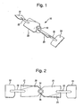
- FIG. 1 is a perspective view of a two bladed, dual direction, impeller in accordance with a preferred embodiment of the present invention.
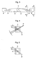
- FIG. 2 is a top view of the impeller shown in FIG. 1.
- FIG. 3 is a side view of the impeller shown in FIG. 1.
- FIG. 4 is an end view of the impeller shown in FIG. 1, showing only one half of the impeller.
- FIG. 5 is a cross-sectional view taken along line 5-5 in FIG. 3 showing only one half of the impeller.
- FIG. 6 is an end view of the impeller shown in FIG. 1.
- FIG. 7 is a schematic view of a mixing apparatus utilizing the impeller of FIG. 1, and showing the general flow path of the material being mixed.
- a two bladed dual direction impeller includes blades that each have an inner blade portion that forces material in a first direction and an outer blade portion that forces material in a second direction opposite to the first direction.
- the inner and outer blade portions are radially spaced by a connector element. Either one or both of the blade portions may be twisted.
- FIGS. 1-6 illustrate a presently preferred embodiment of the present invention.
- a two bladed impeller 10 includes a hub 12 having a bore 14 which can be mounted along an impeller shaft, and a key hole 16 for fixing the impeller 10 to rotate with the shaft.
- the impeller 10 includes two opposed inner blades 20, a connecting rod 22 extending from each of the blades 20, and a outer blade 24 connected by the connecting rod 22 as shown.
- the connecting rod 22 is made small enough so it can have a minimal or insignificant effect on flow in the radial region of the connecting rod 22. Accordingly, the inner blade 20 pumps material in a first direction at the radial region of the inner blade 20.
- the outer blade 24 is angled in the opposite direction of the inner blade 20 so that it moves material in a flow direction opposite the flow direction imparted by the inner blade 20. The material will flow in this opposite direction generally in the radial region of the outer blade 24.
- the connector 22 provides for an intermediate spacing region between the inner blade 20 and the outer blade 24, which is in a radial region of the boundary between the two flow directions. This provides significant advantages of the present invention. Because no particular blade direction is located in the boundary region where the connector 22 is located, turbulence and radial flow in this region can be reduced. This reduces the adverse effects of shear turbulence and/or radial flow of the material that could otherwise occur if the blades 20 and 24 were immediately adjacent each other. Moreover, the surface area of their blades 20 and 24 are located substantially within their respective flow direction areas. This means that energy can be transferred efficiently from the blades to the material along the lengths of the blades 20 and 24.
- This efficient energy transfer allows less energy overall to be directed into the material for the same mixing action as compared to the prior art devices having the blades 20 and 24 immediately adjacent each other.
- This more efficient energy transfer can provide benefits such as reducing the size of the motor required to mix the fluid, reducing the stresses on the motor transmission shaft and impeller, and therefore permitting lighter, less expensive, and/or less bulky components to be used to effect the same degree of mixing in a specific application compared to the prior art. Therefore, the spacing between the blades 20 and 24 provided by the connecting rod 22 provides significant benefits both in reducing shear, turbulence, radial flow and/or high energy effects on the material, and in requiring less energy and force to be applied through the mixing system to accomplish the same degree of mixing flow.
- the inner blade 20 is not completely planar, but has a twisted section generally illustrated as 21 in FIG. 2.
- the twisted section includes an area where the angle of attack of the blade is gradually changing along the section 21, as indicated by the angle A in FIGS. 4 and 5.
- the outer blade 24 is twisted along its length, so that the angle of attack displayed changes along its radial length. This is illustrated by angle B in FIG. 4.
- the use of twisted blades 20 and 24 can provide more efficient pumping, because the angle of attack can be made less in the more radially outward positions. Since the blade speed becomes greater moving radially outward along the blade, this allows the longitudinal mixing force being applied to be balanced as desired along the length of the blade.
- FIG. 7 is a schematic diagram illustrating the general arrangement of a mixer including impellers according to the present invention.
- FIG. 7 illustrates two impellers 10 utilized within a mixing vessel 30.
- a motor 32 drives an impeller shaft 34 that supports the impeller 10.
- Flow is achieved in general as illustrated by the arrows in FIG. 6.
- the vessel 30 may also include longitudinal baffles 36 projecting inwardly to the vessel wall that reduce rotational flow of the materials and thus tend to enhance the vertical vectors of movement.
- the present invention is particularly suitable with relatively medium to high viscosity liquids holding these with solids therein. Because of the desirable novel features of the invention, mixing can be accomplished very efficiently, and the speed of rotation of the impellers can be kept desirably low.
- the invention is particularly suitable for materials such as pseudo-plastic materials that do not keep constant viscosity, and is useful in the manufacture of personal care products, polymer solutions, and/or highly concentrated slurries. Because embodiments of the invention can avoid imparting high energy locally in the blade regions, it is also particularly suitable for mixing materials having crystals, and for applications such as mammalian cell fermentations where it is desirable not to kill the cells.
- the invention can also provide the benefit of achieving higher flow when the same power is being applied to the system compared to prior art impellers.
- a significant benefit of the invention is the ability in some embodiments to provide overall fluid motion without undesirably high localized turbulence, which is particularly beneficial for elevated viscosity transient flow fluids and/or shear sensitive materials.
- the impeller is well suited for applications having a Reynolds number greater than 20 but below 500.
- the invention may perform well at Reynolds numbers beyond this range.
- the ratio of the radial length of the inner blade 20 to the outer blade 24, and the degree of spacing provided by the connector 22, can be selected depending upon the proper application.
- the inner blade has a radial length of 12,55 mm (>4.94 inches) and each outer blade has the length of 5,72 mm (>2.25 inches) radially.
- a gap of approximately two thirds to one half of the outer blade radial length is provided by the connector 22.
- the preferred embodiment has two opposed multi-part "blades" each blade having the two segments and the connector. Impellers according to the invention can also be contracted with three or more multi-part blades.
Landscapes
- Chemical & Material Sciences (AREA)
- Chemical Kinetics & Catalysis (AREA)
- Mixers Of The Rotary Stirring Type (AREA)
Claims (4)
- Rührflügel zur Verwendung in einem Mixergefäß (32), Folgendes umfassend:einen inneren Flügelabschnitt (20), der in eine erste Richtung abgewinkelt ist und einen ebenen ersten Abschnitt (20) umfasst,einen äußeren Flügelabschnitt (24), der radial außerhalb des inneren Flügelabschnitts (20) angeordnet ist,ein Verbindungselement (22), das mit dem inneren Flügelabschnitt (20) und dem äußeren Flügelabschnitt (24) verbunden ist und eine radiale Beabstandung zwischen dem inneren Flügelabschnitt (20) und dem äußeren Flügelabschnitt (24) schafft,wobei der innere Flügelabschnitt (20) eine radiale Länge aufweist, die größer ist als eine radiale Länge des äußeren Flügelabschnitts (24) und wobei der äußere Flügelabschnitt (24) in eine zweite Richtung entgegen der ersten Richtung abgewinkelt ist,dadurch gekennzeichnet, dass der innere Flügelabschnitt (20) einen verdrehten zweiten Abschnitt (21) aufweist, wobei sich ein Anstellwinkel (A) des inneren Flügelabschnitts entlang einer radialen Länge des verdrehten zweiten Abschnitts (21) schrittweise ändert.
- Rührflügel gemäß Anspruch 1, dadurch gekennzeichnet, dass der äußere Flügelabschnitt (24) in seiner Länge verdreht ist, so dass sich ein Anstellwinkel (B) entlang seiner radialen Länge ändert.
- Rührflügel gemäß Anspruch 1 oder 2, dadurch gekennzeichnet, dass das Verbindungselement (22) eine zylindrische Stange ist.
- Rührflügelzusammensetzung (10) zur Verwendung in einem Mixergefäß (32), die eine Nabe (12) und
mindestens einen Rührflügel gemäß Anspruch 1, 2 oder 3 umfasst, wobei sich der Rührflügel unmittelbar von der Nabe weg erstreckt.
Applications Claiming Priority (3)
| Application Number | Priority Date | Filing Date | Title |
|---|---|---|---|
| US82222 | 1987-08-06 | ||
| US10/082,222 US6796707B2 (en) | 2002-02-26 | 2002-02-26 | Dual direction mixing impeller and method |
| PCT/US2003/005637 WO2003072235A1 (en) | 2002-02-26 | 2003-02-26 | Dual direction mixing impeller and method |
Publications (2)
| Publication Number | Publication Date |
|---|---|
| EP1478454A1 EP1478454A1 (de) | 2004-11-24 |
| EP1478454B1 true EP1478454B1 (de) | 2007-11-28 |
Family
ID=27753050
Family Applications (1)
| Application Number | Title | Priority Date | Filing Date |
|---|---|---|---|
| EP03711237A Expired - Lifetime EP1478454B1 (de) | 2002-02-26 | 2003-02-26 | Zweirichtungenmischrotor und verfahren |
Country Status (6)
| Country | Link |
|---|---|
| US (1) | US6796707B2 (de) |
| EP (1) | EP1478454B1 (de) |
| AU (1) | AU2003213556B2 (de) |
| CA (1) | CA2477064C (de) |
| DE (1) | DE60317772T2 (de) |
| WO (1) | WO2003072235A1 (de) |
Families Citing this family (22)
| Publication number | Priority date | Publication date | Assignee | Title |
|---|---|---|---|---|
| WO2003074164A1 (en) * | 2002-03-01 | 2003-09-12 | Glaxo Group Limited | Rotary blending apparatus and system |
| US7278598B2 (en) * | 2004-01-23 | 2007-10-09 | Vita-Mix Corporation | Blender blade |
| US8790913B2 (en) | 2005-10-26 | 2014-07-29 | Pbs Biotech, Inc. | Methods of using pneumatic bioreactors |
| US7628528B2 (en) * | 2005-10-26 | 2009-12-08 | PRS Biotech, Inc. | Pneumatic bioreactor |
| GB2437930A (en) | 2006-05-10 | 2007-11-14 | Lucite Int Uk Ltd | Mixing apparatus |
| US7713730B2 (en) | 2007-04-24 | 2010-05-11 | Pbs Biotech, Inc. | Pneumatic bioreactor |
| WO2009132192A2 (en) * | 2008-04-25 | 2009-10-29 | Pbs Biotech, Inc. | Bioreactor apparatus |
| US8152362B2 (en) * | 2008-10-17 | 2012-04-10 | Dci, Inc. | Mixer and methods of mixing |
| US8220986B2 (en) * | 2008-11-19 | 2012-07-17 | Chemineer, Inc. | High efficiency mixer-impeller |
| WO2010082391A1 (ja) * | 2009-01-16 | 2010-07-22 | Dic株式会社 | 撹拌装置及び撹拌方法 |
| KR20120064693A (ko) | 2009-08-31 | 2012-06-19 | 다우 글로벌 테크놀로지스 엘엘씨 | 혼합 디바이스 및 동적 혼합 방법 |
| EP2926892B1 (de) * | 2014-04-04 | 2021-01-13 | Milton Roy Europe | Rührgerät |
| KR102408877B1 (ko) | 2014-08-13 | 2022-06-13 | 베르살리스 에스.피.에이. | 회전자 및 교반 디바이스 |
| CN108579496A (zh) * | 2016-06-01 | 2018-09-28 | 姜纲法 | 一种纺织用印染染料搅拌机构 |
| KR101763681B1 (ko) * | 2017-03-20 | 2017-08-14 | 민수진 | 육계가공장치 |
| KR101779102B1 (ko) | 2017-03-23 | 2017-09-18 | 이병복 | 고기류염지장치 |
| KR101869658B1 (ko) * | 2017-09-11 | 2018-06-20 | 이병복 | 고기류염지장치 |
| CN108893249A (zh) * | 2018-06-28 | 2018-11-27 | 广西驰胜农业科技有限公司 | 微生物发酵及搅拌反应器 |
| KR102153523B1 (ko) | 2020-01-22 | 2020-09-08 | 주식회사 한울엔지니어링 | 고점도 유체 교반용 임펠러 |
| EP4100153A1 (de) * | 2020-02-03 | 2022-12-14 | Life Technologies Corporation | Flüssigkeitsmischsysteme mit modularen laufrädern und zugehörige verfahren |
| DE102020109865A1 (de) | 2020-04-08 | 2021-10-14 | EKATO Rühr- und Mischtechnik GmbH | Verfahren und Rührorganvorrichtung zur Durchmischung von mittelviskosen bis hochviskosen Fluiden und/oder Pasten |
| CN114227974B (zh) * | 2021-12-17 | 2023-01-20 | 沭阳林冉塑业有限公司 | 一种环保型塑料加工搅拌装置 |
Family Cites Families (9)
| Publication number | Priority date | Publication date | Assignee | Title |
|---|---|---|---|---|
| US374989A (en) * | 1887-12-20 | Car-coupling | ||
| DE1101113B (de) | 1952-03-17 | 1961-03-02 | Wilhelm Loedige | Mischeinrichtung |
| AT265214B (de) | 1964-12-29 | 1968-10-10 | Erich Karl Todtenhaupt | Vorrichtung zur Herstellung gleichmäßiger Dispersionen |
| US3365176A (en) | 1966-10-07 | 1968-01-23 | Phillips Petroleum Co | Agitator apparatus |
| DE2531646A1 (de) * | 1975-07-15 | 1977-02-03 | Ekato Werke | Verfahren und vorrichtung zur herstellung von tonerde |
| DE3776145D1 (de) | 1987-09-03 | 1992-02-27 | Bauko Baukooperation Gmbh | Ruehrwerkzeug fuer eine industrielle misch- oder ruehrmaschine. |
| JPH02273531A (ja) * | 1989-04-17 | 1990-11-08 | Hitachi Ltd | 撹拌装置 |
| US5052892A (en) * | 1990-01-29 | 1991-10-01 | Chemineer, Inc. | High efficiency mixer impeller |
| DE19952760A1 (de) | 1999-11-02 | 2001-05-23 | Franz Durst | Rührelement |
-
2002
- 2002-02-26 US US10/082,222 patent/US6796707B2/en not_active Expired - Lifetime
-
2003
- 2003-02-26 WO PCT/US2003/005637 patent/WO2003072235A1/en not_active Ceased
- 2003-02-26 DE DE60317772T patent/DE60317772T2/de not_active Expired - Lifetime
- 2003-02-26 AU AU2003213556A patent/AU2003213556B2/en not_active Expired
- 2003-02-26 CA CA002477064A patent/CA2477064C/en not_active Expired - Lifetime
- 2003-02-26 EP EP03711237A patent/EP1478454B1/de not_active Expired - Lifetime
Also Published As
| Publication number | Publication date |
|---|---|
| CA2477064C (en) | 2009-09-01 |
| US20030161216A1 (en) | 2003-08-28 |
| DE60317772T2 (de) | 2008-11-20 |
| EP1478454A1 (de) | 2004-11-24 |
| AU2003213556B2 (en) | 2008-05-22 |
| WO2003072235A1 (en) | 2003-09-04 |
| US6796707B2 (en) | 2004-09-28 |
| DE60317772D1 (de) | 2008-01-10 |
| AU2003213556A1 (en) | 2003-09-09 |
| CA2477064A1 (en) | 2003-09-04 |
Similar Documents
| Publication | Publication Date | Title |
|---|---|---|
| EP1478454B1 (de) | Zweirichtungenmischrotor und verfahren | |
| CN1245251C (zh) | 动力混合器 | |
| EP0078660B1 (de) | Mischrotor mit Axialflusswirkung | |
| EP0469302B1 (de) | Mischungsrührer und Mischungssysteme zum Mischen von Flüssigkeiten und Flüssigkeitssuspensionen mit einem weiten Viskositätsbereich | |
| US5158434A (en) | Mixing impellers and impeller systems for mixing and blending liquids and liquid suspensions having a wide range of viscosities | |
| US20100309746A1 (en) | Ultraclean Magnetic Mixer with Shear-Facilitating Blade Openings | |
| US5246289A (en) | Agitator having streamlined blades for reduced cavitation | |
| KR100455952B1 (ko) | 세로형 교반장치 | |
| EP2227315B1 (de) | Mischeranordnung und verfahren zur strömungssteuerung in einer mischeranordnung | |
| US6210123B1 (en) | Jet pumping device | |
| CN107159041A (zh) | 一种非接触式磁力传动搅拌装置 | |
| CN1466484A (zh) | 用于搅拌流动或松散介质尤其是高粘度介质的装置 | |
| CN102302906B (zh) | 一种静动结合高效液-液混合装置 | |
| EP0647467B1 (de) | Einheitlicher, einstückiger, drehbarer Mischer und Abgabekopf | |
| CN113056325B (zh) | 磁性耦接的液体混合器 | |
| EP1165219B1 (de) | Mischvorrichtung | |
| CN204073996U (zh) | 一种宽螺带锯齿搅拌器 | |
| CN107715726A (zh) | 一种新型组合式混合搅拌桨 | |
| CN114452857A (zh) | 具备正反交混流的搅拌设备 | |
| US11406949B2 (en) | Apparatus for agitation of fluids | |
| CN213610980U (zh) | 用于油橄榄保健食品加工的固液物料混合搅装置 | |
| RU2253506C1 (ru) | Пропеллерная мешалка конструкции землякова н.в. для перемешивания жидких сред | |
| JP3203174B2 (ja) | 高粘度液処理兼高速度液体処理装置 | |
| SU1673187A1 (ru) | Смеситель | |
| KR20230076748A (ko) | 공중합 아라미드용 고 점성용 고성능 저 부하 교반기 |
Legal Events
| Date | Code | Title | Description |
|---|---|---|---|
| PUAI | Public reference made under article 153(3) epc to a published international application that has entered the european phase |
Free format text: ORIGINAL CODE: 0009012 |
|
| AK | Designated contracting states |
Kind code of ref document: A1 Designated state(s): AT BE BG CH CY CZ DE DK EE ES FI FR GB GR HU IE IT LI LU MC NL PT SE SI SK TR |
|
| AX | Request for extension of the european patent |
Extension state: AL LT LV MK RO |
|
| 17P | Request for examination filed |
Effective date: 20041206 |
|
| 17Q | First examination report despatched |
Effective date: 20050503 |
|
| GRAP | Despatch of communication of intention to grant a patent |
Free format text: ORIGINAL CODE: EPIDOSNIGR1 |
|
| GRAS | Grant fee paid |
Free format text: ORIGINAL CODE: EPIDOSNIGR3 |
|
| GRAA | (expected) grant |
Free format text: ORIGINAL CODE: 0009210 |
|
| AK | Designated contracting states |
Kind code of ref document: B1 Designated state(s): AT BE BG CH CY CZ DE DK EE ES FI FR GB GR HU IE IT LI LU MC NL PT SE SI SK TR |
|
| REG | Reference to a national code |
Ref country code: GB Ref legal event code: FG4D |
|
| REG | Reference to a national code |
Ref country code: IE Ref legal event code: FG4D |
|
| REG | Reference to a national code |
Ref country code: CH Ref legal event code: EP |
|
| REF | Corresponds to: |
Ref document number: 60317772 Country of ref document: DE Date of ref document: 20080110 Kind code of ref document: P |
|
| PG25 | Lapsed in a contracting state [announced via postgrant information from national office to epo] |
Ref country code: SE Free format text: LAPSE BECAUSE OF FAILURE TO SUBMIT A TRANSLATION OF THE DESCRIPTION OR TO PAY THE FEE WITHIN THE PRESCRIBED TIME-LIMIT Effective date: 20080228 Ref country code: NL Free format text: LAPSE BECAUSE OF FAILURE TO SUBMIT A TRANSLATION OF THE DESCRIPTION OR TO PAY THE FEE WITHIN THE PRESCRIBED TIME-LIMIT Effective date: 20071128 Ref country code: CH Free format text: LAPSE BECAUSE OF FAILURE TO SUBMIT A TRANSLATION OF THE DESCRIPTION OR TO PAY THE FEE WITHIN THE PRESCRIBED TIME-LIMIT Effective date: 20071128 Ref country code: ES Free format text: LAPSE BECAUSE OF FAILURE TO SUBMIT A TRANSLATION OF THE DESCRIPTION OR TO PAY THE FEE WITHIN THE PRESCRIBED TIME-LIMIT Effective date: 20080311 Ref country code: LI Free format text: LAPSE BECAUSE OF FAILURE TO SUBMIT A TRANSLATION OF THE DESCRIPTION OR TO PAY THE FEE WITHIN THE PRESCRIBED TIME-LIMIT Effective date: 20071128 |
|
| NLV1 | Nl: lapsed or annulled due to failure to fulfill the requirements of art. 29p and 29m of the patents act | ||
| PG25 | Lapsed in a contracting state [announced via postgrant information from national office to epo] |
Ref country code: BG Free format text: LAPSE BECAUSE OF FAILURE TO SUBMIT A TRANSLATION OF THE DESCRIPTION OR TO PAY THE FEE WITHIN THE PRESCRIBED TIME-LIMIT Effective date: 20080228 Ref country code: SI Free format text: LAPSE BECAUSE OF FAILURE TO SUBMIT A TRANSLATION OF THE DESCRIPTION OR TO PAY THE FEE WITHIN THE PRESCRIBED TIME-LIMIT Effective date: 20071128 Ref country code: FI Free format text: LAPSE BECAUSE OF FAILURE TO SUBMIT A TRANSLATION OF THE DESCRIPTION OR TO PAY THE FEE WITHIN THE PRESCRIBED TIME-LIMIT Effective date: 20071128 |
|
| REG | Reference to a national code |
Ref country code: CH Ref legal event code: PL |
|
| PG25 | Lapsed in a contracting state [announced via postgrant information from national office to epo] |
Ref country code: AT Free format text: LAPSE BECAUSE OF FAILURE TO SUBMIT A TRANSLATION OF THE DESCRIPTION OR TO PAY THE FEE WITHIN THE PRESCRIBED TIME-LIMIT Effective date: 20071128 |
|
| PG25 | Lapsed in a contracting state [announced via postgrant information from national office to epo] |
Ref country code: DK Free format text: LAPSE BECAUSE OF FAILURE TO SUBMIT A TRANSLATION OF THE DESCRIPTION OR TO PAY THE FEE WITHIN THE PRESCRIBED TIME-LIMIT Effective date: 20071128 Ref country code: CZ Free format text: LAPSE BECAUSE OF FAILURE TO SUBMIT A TRANSLATION OF THE DESCRIPTION OR TO PAY THE FEE WITHIN THE PRESCRIBED TIME-LIMIT Effective date: 20071128 |
|
| PG25 | Lapsed in a contracting state [announced via postgrant information from national office to epo] |
Ref country code: SK Free format text: LAPSE BECAUSE OF FAILURE TO SUBMIT A TRANSLATION OF THE DESCRIPTION OR TO PAY THE FEE WITHIN THE PRESCRIBED TIME-LIMIT Effective date: 20071128 Ref country code: BE Free format text: LAPSE BECAUSE OF FAILURE TO SUBMIT A TRANSLATION OF THE DESCRIPTION OR TO PAY THE FEE WITHIN THE PRESCRIBED TIME-LIMIT Effective date: 20071128 |
|
| EN | Fr: translation not filed | ||
| PG25 | Lapsed in a contracting state [announced via postgrant information from national office to epo] |
Ref country code: PT Free format text: LAPSE BECAUSE OF FAILURE TO SUBMIT A TRANSLATION OF THE DESCRIPTION OR TO PAY THE FEE WITHIN THE PRESCRIBED TIME-LIMIT Effective date: 20080428 |
|
| PLBE | No opposition filed within time limit |
Free format text: ORIGINAL CODE: 0009261 |
|
| STAA | Information on the status of an ep patent application or granted ep patent |
Free format text: STATUS: NO OPPOSITION FILED WITHIN TIME LIMIT |
|
| PG25 | Lapsed in a contracting state [announced via postgrant information from national office to epo] |
Ref country code: MC Free format text: LAPSE BECAUSE OF NON-PAYMENT OF DUE FEES Effective date: 20080228 Ref country code: FR Free format text: LAPSE BECAUSE OF FAILURE TO SUBMIT A TRANSLATION OF THE DESCRIPTION OR TO PAY THE FEE WITHIN THE PRESCRIBED TIME-LIMIT Effective date: 20080912 |
|
| 26N | No opposition filed |
Effective date: 20080829 |
|
| PG25 | Lapsed in a contracting state [announced via postgrant information from national office to epo] |
Ref country code: IE Free format text: LAPSE BECAUSE OF NON-PAYMENT OF DUE FEES Effective date: 20080226 Ref country code: EE Free format text: LAPSE BECAUSE OF FAILURE TO SUBMIT A TRANSLATION OF THE DESCRIPTION OR TO PAY THE FEE WITHIN THE PRESCRIBED TIME-LIMIT Effective date: 20071128 Ref country code: GR Free format text: LAPSE BECAUSE OF FAILURE TO SUBMIT A TRANSLATION OF THE DESCRIPTION OR TO PAY THE FEE WITHIN THE PRESCRIBED TIME-LIMIT Effective date: 20080229 |
|
| PG25 | Lapsed in a contracting state [announced via postgrant information from national office to epo] |
Ref country code: CY Free format text: LAPSE BECAUSE OF FAILURE TO SUBMIT A TRANSLATION OF THE DESCRIPTION OR TO PAY THE FEE WITHIN THE PRESCRIBED TIME-LIMIT Effective date: 20071128 |
|
| PG25 | Lapsed in a contracting state [announced via postgrant information from national office to epo] |
Ref country code: LU Free format text: LAPSE BECAUSE OF NON-PAYMENT OF DUE FEES Effective date: 20080226 Ref country code: HU Free format text: LAPSE BECAUSE OF FAILURE TO SUBMIT A TRANSLATION OF THE DESCRIPTION OR TO PAY THE FEE WITHIN THE PRESCRIBED TIME-LIMIT Effective date: 20080529 |
|
| PG25 | Lapsed in a contracting state [announced via postgrant information from national office to epo] |
Ref country code: TR Free format text: LAPSE BECAUSE OF FAILURE TO SUBMIT A TRANSLATION OF THE DESCRIPTION OR TO PAY THE FEE WITHIN THE PRESCRIBED TIME-LIMIT Effective date: 20071128 |
|
| PG25 | Lapsed in a contracting state [announced via postgrant information from national office to epo] |
Ref country code: IT Free format text: LAPSE BECAUSE OF NON-PAYMENT OF DUE FEES Effective date: 20080229 |
|
| REG | Reference to a national code |
Ref country code: DE Ref legal event code: R082 Ref document number: 60317772 Country of ref document: DE Representative=s name: LANG & TOMERIUS PATENTANWALTSPARTNERSCHFT MBB, DE Ref country code: DE Ref legal event code: R081 Ref document number: 60317772 Country of ref document: DE Owner name: GIGAS, BERND, CHURCHVILLE, US Free format text: FORMER OWNERS: SPX CORPORATION, CHARLOTTE, N.C., US; GIGAS, BERND, CHURCHVILLE, N.Y., US; HOWK, RICHARD, PITTSFORD, N.Y., US Ref country code: DE Ref legal event code: R081 Ref document number: 60317772 Country of ref document: DE Owner name: SPX FLOW, INC. (N. D. GES. D. STAATES DELAWARE, US Free format text: FORMER OWNERS: SPX CORPORATION, CHARLOTTE, N.C., US; GIGAS, BERND, CHURCHVILLE, N.Y., US; HOWK, RICHARD, PITTSFORD, N.Y., US Ref country code: DE Ref legal event code: R081 Ref document number: 60317772 Country of ref document: DE Owner name: HOWK, RICHARD, PITTSFORD, US Free format text: FORMER OWNERS: SPX CORPORATION, CHARLOTTE, N.C., US; GIGAS, BERND, CHURCHVILLE, N.Y., US; HOWK, RICHARD, PITTSFORD, N.Y., US Ref country code: DE Ref legal event code: R082 Ref document number: 60317772 Country of ref document: DE Representative=s name: LANG & TOMERIUS PATENTANWALTSPARTNERSCHAFT MBB, DE |
|
| REG | Reference to a national code |
Ref country code: GB Ref legal event code: 732E Free format text: REGISTERED BETWEEN 20170427 AND 20170503 |
|
| REG | Reference to a national code |
Ref country code: DE Ref legal event code: R079 Ref document number: 60317772 Country of ref document: DE Free format text: PREVIOUS MAIN CLASS: B01F0015000000 Ipc: B01F0035000000 |
|
| PGFP | Annual fee paid to national office [announced via postgrant information from national office to epo] |
Ref country code: GB Payment date: 20220225 Year of fee payment: 20 Ref country code: DE Payment date: 20220225 Year of fee payment: 20 |
|
| REG | Reference to a national code |
Ref country code: DE Ref legal event code: R071 Ref document number: 60317772 Country of ref document: DE |
|
| REG | Reference to a national code |
Ref country code: GB Ref legal event code: PE20 Expiry date: 20230225 |
|
| PG25 | Lapsed in a contracting state [announced via postgrant information from national office to epo] |
Ref country code: GB Free format text: LAPSE BECAUSE OF EXPIRATION OF PROTECTION Effective date: 20230225 |