EP0647468B1 - Appareil agitateur - Google Patents
Appareil agitateur Download PDFInfo
- Publication number
- EP0647468B1 EP0647468B1 EP94116106A EP94116106A EP0647468B1 EP 0647468 B1 EP0647468 B1 EP 0647468B1 EP 94116106 A EP94116106 A EP 94116106A EP 94116106 A EP94116106 A EP 94116106A EP 0647468 B1 EP0647468 B1 EP 0647468B1
- Authority
- EP
- European Patent Office
- Prior art keywords
- blades
- stirring
- vertical flat
- blade
- vessel
- Prior art date
- Legal status (The legal status is an assumption and is not a legal conclusion. Google has not performed a legal analysis and makes no representation as to the accuracy of the status listed.)
- Expired - Lifetime
Links
- 238000003756 stirring Methods 0.000 title claims description 112
- 239000007788 liquid Substances 0.000 claims description 24
- 230000001174 ascending effect Effects 0.000 description 6
- 239000000463 material Substances 0.000 description 6
- 239000012530 fluid Substances 0.000 description 4
- 230000015572 biosynthetic process Effects 0.000 description 2
- 238000006243 chemical reaction Methods 0.000 description 2
- 230000000694 effects Effects 0.000 description 2
- AKHNMLFCWUSKQB-UHFFFAOYSA-L sodium thiosulfate Chemical compound [Na+].[Na+].[O-]S([O-])(=O)=S AKHNMLFCWUSKQB-UHFFFAOYSA-L 0.000 description 2
- 239000004925 Acrylic resin Substances 0.000 description 1
- 229920000178 Acrylic resin Polymers 0.000 description 1
- 244000062793 Sorghum vulgare Species 0.000 description 1
- 238000005452 bending Methods 0.000 description 1
- 238000004140 cleaning Methods 0.000 description 1
- 238000010276 construction Methods 0.000 description 1
- 230000008878 coupling Effects 0.000 description 1
- 238000010168 coupling process Methods 0.000 description 1
- 238000005859 coupling reaction Methods 0.000 description 1
- 239000011346 highly viscous material Substances 0.000 description 1
- 235000015110 jellies Nutrition 0.000 description 1
- 239000008274 jelly Substances 0.000 description 1
- 238000004519 manufacturing process Methods 0.000 description 1
- 235000019713 millet Nutrition 0.000 description 1
- 230000001737 promoting effect Effects 0.000 description 1
Images


Classifications
-
- B—PERFORMING OPERATIONS; TRANSPORTING
- B01—PHYSICAL OR CHEMICAL PROCESSES OR APPARATUS IN GENERAL
- B01F—MIXING, e.g. DISSOLVING, EMULSIFYING OR DISPERSING
- B01F27/00—Mixers with rotary stirring devices in fixed receptacles; Kneaders
- B01F27/05—Stirrers
- B01F27/11—Stirrers characterised by the configuration of the stirrers
- B01F27/114—Helically shaped stirrers, i.e. stirrers comprising a helically shaped band or helically shaped band sections
- B01F27/1145—Helically shaped stirrers, i.e. stirrers comprising a helically shaped band or helically shaped band sections ribbon shaped with an open space between the helical ribbon flight and the rotating axis
-
- B—PERFORMING OPERATIONS; TRANSPORTING
- B01—PHYSICAL OR CHEMICAL PROCESSES OR APPARATUS IN GENERAL
- B01F—MIXING, e.g. DISSOLVING, EMULSIFYING OR DISPERSING
- B01F27/00—Mixers with rotary stirring devices in fixed receptacles; Kneaders
- B01F27/05—Stirrers
- B01F27/11—Stirrers characterised by the configuration of the stirrers
- B01F27/112—Stirrers characterised by the configuration of the stirrers with arms, paddles, vanes or blades
- B01F27/1125—Stirrers characterised by the configuration of the stirrers with arms, paddles, vanes or blades with vanes or blades extending parallel or oblique to the stirrer axis
Definitions
- the present invention relates to a stirring apparatus available for the purpose of various stirring operations including mixing and reaction operations, for instance, stirring of a liquid-liquid system of solutions having different viscosities, stirring of a solid-liquid system of slurry-like materials or the like.
- stirring blades equipped in heretofore known stirring apparatuses paddle blades, turbine blades, propeller blades, multi-stage paddle blades or the like were used for stirring a fluid having a low viscosity
- helical ribbon blades, screw blades or the like were used for stirring a fluid having a high viscosity.
- a stirring apparatus for reactions of highly viscous materials is known from DE-38 17 380 A1 and comprises a vessel in which a rotary stirring shaft is disposed vertically.
- a vertical flat blade is mounted on one side of the stirring shaft parallel to the axis thereof.
- An inclined flat blade is mounted on the other side of the stirring shaft opposite to the vertical flat blade at an angle with respect to the axis of the stirring shaft. The blades are disposed so as to not come in contact with the vessel.
- an improved stirring apparatus comprises a vertical flat blade mounted on one side of a rotary stirring shaft disposed vertically within a vessel and parallel to the axis of the stirring shaft; a plurality of first inclined flat blades mounted on the other side of said stirring shaft in the range of the mounting height of said vertical flat blade at an angle with respect to the axis of the stirring shaft and spaced from one another so as to generate a descending flow; a first vertical flat blade with a sweptback portion, this blade being positioned directly under said first inclined flat blades and mounted on said stirring shaft parallel to its axis; one or a plurality of second inclined flat blades positioned directly under the vertical flat blade at an angle with respect to the axis of said stirring shaft and spaced from one another so as to generate a descending flow; a second vertical flat blade with a sweptback portion, this second vertical flat blade being positioned directly under the second inclined flat blades in the range of the mounting height of said first vertical flat blade with the sweptback portion and mounted in parallel to the axi
- the above-mentioned vertical flat blade, first and second inclined flat blades and first and second vertical flat blades each with the sweptback portion are disposed in the range from a bottom surface to the proximity of a level of liquid to be processed within the vessel.
- baffle plates disposed vertically on the inner wall surface of the vessel.
- baffle plates disposed vertically on the inner wall surface of the vessel generation of revolving flows in the inner circumferential direction within the vessel is prevented, and so, formation of ascending flows and descending flows over the entire region within the vessel is promoted.
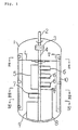
- a rotary shaft 2 arranged vertically is inserted into a cylinder-shaped vertical type stirring vessel 1 in which two or more kinds of liquids having different viscosities are accommodated, and this rotary shaft 2 is connected via a shaft coupling 3 to a stirring shaft 4 disposed vertically at the central portion of the stirring vessel 1.
- first and second inclined flat blades 6 and 7, and first and second vertical flat blades 8 and 9 each provided with a sweptback blade-portion.
- the vertical flat blade 5 is mounted on one side of the stirring shaft 4 in parallel to the axis of the stirring shaft 4.
- first inclined flat blades 6 on the opposite side to the vertical flat blade 5 of the stirring shaft 4 are mounted a plurality of first inclined flat blades 6 as spaced from one another and at an angle with respect to the axis of the stirring shaft 4.
- a first vertical flat blade 8 provided with a sweptback blade-portion is mounted on the circumference of the stirring shaft 4 in parallel to its axis at the position in the same orientation as the first inclined flat blades 6.
- a second inclined flat blade or blades 7 are mounted on the stirring shaft 4 as spaced from one another and at an angle with respect to the axis of the stirring shaft 4, and a second vertical flat blade 9 provided with a sweptback blade-portion is mounted on the stirring shaft in parallel to its axis.
- the second inclined flat blade or blades 7 are positioned above the second vertical flat blade 9 with the sweptback portion as spaced from one another, and the both blades 7 and 9 are positioned on the circumference of the stirring shaft in the same orientation as the vertical flat blade 5.
- first and second inclined flat blades 6 and 7 are disposed in parallel to one another at an equal inclination angle with respect to the axis of the stirring shaft 4 so that descending flows may be generated in the liquid to be processed within the stirring vessel 1 when the stirring shaft 4 rotates (the direction of rotation being indicated by an arrow in Fig. 1).
- the sweptback portions of the above-described first and second vertical flat blades 8 and 9 are formed at the tip end portions of the same blades 8 and 9 and they are bent towards the back side with respect to the direction of rotation of the stirring shaft 4. Furthermore, the above-described various blades in the upper region and in the lower region disposed in the above-described manner on the stirring shaft 4 directed in the vertical direction, are arranged vertically in the range from the position near to the bottom surface up to the proximity of a level L of the liquid to be processed within the stirring vessel 1.
- baffle plates 10 On the inner wall surface of the stirring vessel 1 are equipped a plurality of baffle plates 10 directed vertically and extending from the bottom surface of the stirring vessel 1 up to the proximity of an upper limit of the level of the liquid to be processed. These baffle plates 10 have the effects of preventing generation of revolving flows along the inner circumference of the stirring vessel 1 caused by the above-described various stirring blades 5 to 9 at the time of stirring, and promoting formation of ascending flows and descending flows extending over the entire region within the stirring vessel 1.
- the stirring shaft 4 when the stirring shaft 4 is rotationally driven via the rotary shaft 2 within the stirring vessel 1 filled with two or more kinds of liquids having different viscosities, the stirring blades 5 - 9 rotate about the axis of the stirring shaft 4.
- the vertical flat blade 5 and the first and second vertical flat blades 8 and 9 each provided with the sweptback blade-portion, outward radial flows of the liquids to be processed towards the inner wall surface of the stirring vessel 1 are generated, and these radial flows collide against the inner wall surface of the stirring vessel 1 and become ascending flows along the wall surface of the straight cylinder portion of the stirring vessel 1.
- stirring vessel 1 there is formed large circulating flows over its entire region, and so, two or more kinds of liquids having different viscosities can be mixed efficiently.
- Fig. 6 shows a state of flows of liquids to be processed within the stirring vessel 1 in the case where two or more kinds of liquids having different viscosities are stirred by making use of the stirring apparatus according to the above-described embodiment of the present invention, and in this figure, the above-described flows of liquids within the stirring vessel 1 are indicated by arrows.
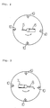
- the radial dimensions of the first and second vertical flat blades 8 and 9 each provided with the sweptback blade-portion are chosen to be 50 - 70% of the radial dimension of the stirring vessel 1.
- the bent position of their sweptback portions is preferably chosen at the position of 70 - 80% of their radial dimensions with reference to the axis of the stirring shaft 4.
- the radial dimension of the vertical flat blade 5 at the above smaller than the radial dimensions of the first and second vertical flat blades 8 and 9 each provided with the sweptback blade-portion at the below. It is necessary that the dimensions in the direction of height of the vertical flat blade 5 and the first and second vertical flat blades 8 and 9 are determined so that a bending moment in the stirring shaft caused by the loads acting upon the respective blades at the time of stirring may become minimum.
- a torque meter was equipped in the driving device for the stirring blades to measure a torque during stirring or mixing operations, and
Landscapes
- Chemical & Material Sciences (AREA)
- Chemical Kinetics & Catalysis (AREA)
- Mixers Of The Rotary Stirring Type (AREA)
Claims (3)
- Appareil agitateur comprenant une paie plate verticale (5) montée sur un côté d'un arbre agitateur rotatif (4) disposé verticalement à l'intérieur d'une cuve (1) et parallèle à l'axe de l'arbre agitateur (4) ;une pluralité de premières pales plates inclinées (6) montées sur l'autre côté dudit arbre agitateur (4) sur une zone à la même hauteur de montage que ladite pale plate verticale (5) à un angle par rapport à l'axe de l'arbre agitateur, et espacées l'une de l'autre, de façon à générer un flux descendant ;une première pale plate verticale (8) à portion déviée, cette pale étant positionnée directement en dessous desdites premières pales plates inclinées (6) et montée sur ledit arbre agitateur (4) parallèlement à son axe ;une ou plusieurs deuxièmes pales plates inclinées (7) positionnées directement en dessous de la pale plate verticale (5) à un certain angle par rapport à l'axe dudit arbre agitateur (4) et espacées l'une de l'autre de façon à générer un flux descendant ;une deuxième paie plate verticale (9) à portion déviée, cette deuxième paie plate verticale (9) étant positionnée directement en dessous des deuxièmes pales plates inclinées (7) sur une zone à la même hauteur de montage que ladite première pale plate verticale (8) à portion déviée et montée parallèlement à l'axe dudit arbre agitateur (4) ;de telle sorte que lesdites premières et deuxièmes pales plates inclinées (6, 7) aient des bords d'attaque et de fuite horizontaux et que les pales soient inclinées par rapport à un plan horizontal ;
de telle sorte que les portions déviées des première et deuxième pales plates verticales (8, 9) soient des sections extérieures de chaque pale respective qui sont repliées dans la direction opposée à la rotation des pales ; et
de telle sorte que ladite pale plate verticale (5), lesdites premières et deuxièmes pales plates inclinées (6, 7) et lesdites première et deuxième pales plates verticales (8, 9) à portion déviée soient disposées de façon à ne pas entrer en contact avec ladite cuve (1). - Appareil agitateur selon la revendication 1, dans lequel ladite pale plate verticale (5), lesdites premières et deuxièmes pales plates inclinées (6, 7) et lesdites première et deuxième pales plates verticales (8, 9) à portion déviée sont disposées sur une zone comprise entre une surface inférieure et la proximité d'un niveau (L) de liquide à traiter à l'intérieur de la cuve (1).
- Appareil agitateur selon la revendication 1 ou 2, dans lequel ledit appareil est pourvu de contreagitateurs (10) disposés verticalement sur la surface de la paroi intérieure de la cuve (1).
Applications Claiming Priority (2)
| Application Number | Priority Date | Filing Date | Title |
|---|---|---|---|
| JP5254145A JP2516730B2 (ja) | 1993-10-12 | 1993-10-12 | 攪拌装置 |
| JP254145/93 | 1993-10-12 |
Publications (2)
| Publication Number | Publication Date |
|---|---|
| EP0647468A1 EP0647468A1 (fr) | 1995-04-12 |
| EP0647468B1 true EP0647468B1 (fr) | 1997-04-09 |
Family
ID=17260853
Family Applications (1)
| Application Number | Title | Priority Date | Filing Date |
|---|---|---|---|
| EP94116106A Expired - Lifetime EP0647468B1 (fr) | 1993-10-12 | 1994-10-12 | Appareil agitateur |
Country Status (4)
| Country | Link |
|---|---|
| US (1) | US5472278A (fr) |
| EP (1) | EP0647468B1 (fr) |
| JP (1) | JP2516730B2 (fr) |
| DE (1) | DE69402499T2 (fr) |
Cited By (3)
| Publication number | Priority date | Publication date | Assignee | Title |
|---|---|---|---|---|
| CN106076143A (zh) * | 2016-07-29 | 2016-11-09 | 无锡乐华自动化科技有限公司 | 一种带振动的多功能搅拌装置及其搅拌方法 |
| CN106139990A (zh) * | 2016-07-29 | 2016-11-23 | 无锡乐华自动化科技有限公司 | 一种多功能搅拌装置及其搅拌方法 |
| CN106215746A (zh) * | 2016-07-29 | 2016-12-14 | 无锡乐华自动化科技有限公司 | 一种搅拌装置及其搅拌方法 |
Families Citing this family (27)
| Publication number | Priority date | Publication date | Assignee | Title |
|---|---|---|---|---|
| JPH0929084A (ja) * | 1995-07-21 | 1997-02-04 | Fuji Photo Film Co Ltd | 攪拌装置 |
| US6455316B1 (en) | 1998-08-13 | 2002-09-24 | Symyx Technologies, Inc. | Parallel reactor with internal sensing and method of using same |
| US6306658B1 (en) | 1998-08-13 | 2001-10-23 | Symyx Technologies | Parallel reactor with internal sensing |
| US6787112B1 (en) | 1998-08-13 | 2004-09-07 | Symyx Technologies, Inc. | Parallel reactor with internal sensing and method of using same |
| US6703055B1 (en) | 1999-09-01 | 2004-03-09 | Daniel Klein | Wine fermentation cap management and pomace removal |
| AUPQ503900A0 (en) * | 2000-01-11 | 2000-02-03 | Commonwealth Scientific And Industrial Research Organisation | Apparatus for mixing |
| US6994827B2 (en) | 2000-06-03 | 2006-02-07 | Symyx Technologies, Inc. | Parallel semicontinuous or continuous reactors |
| US6508583B1 (en) * | 2000-11-28 | 2003-01-21 | E. I. Du Pont De Nemours And Company | Agitated vessel for producing a suspension of solids |
| JP4979158B2 (ja) * | 2001-03-28 | 2012-07-18 | 日本化学機械製造株式会社 | 攪拌装置 |
| JP2003033635A (ja) * | 2001-05-17 | 2003-02-04 | Shinko Pantec Co Ltd | 攪拌翼およびこれを用いた攪拌装置ならびに攪拌方法 |
| US6582116B2 (en) * | 2001-09-24 | 2003-06-24 | Symyx Technologies, Inc. | Apparatus and method for mixing small volumes of reaction materials |
| US6682215B2 (en) * | 2002-04-10 | 2004-01-27 | Fibermark, Inc. | Process and apparatus for making sheet of fibers using a foamed medium |
| US6830656B2 (en) * | 2002-04-30 | 2004-12-14 | Fibermark, Inc. | Non-woven fiber webs with nylon binder |
| FR2850039B1 (fr) * | 2003-01-21 | 2006-06-02 | Dietrich Process Systems De | Brise-lames solidarise a distance de la paroi interne d'un contenant emaille par un raccordement local |
| US7434538B2 (en) * | 2003-04-10 | 2008-10-14 | Allied Precision Industries, Inc. | Water agitation system for water retention structure |
| KR100968757B1 (ko) * | 2003-06-27 | 2010-07-09 | 주식회사 포스코 | 고형분 알칼리 용액 혼합장치 |
| US7172337B2 (en) * | 2003-07-08 | 2007-02-06 | Philadelphia Mixing Solutions, A Division Of Philadelphia Gear Corporation | Low shear impeller |
| US6969491B1 (en) * | 2004-09-01 | 2005-11-29 | 3M Innovative Properties Company | Stirred tube reactor and method of using the same |
| JP4701056B2 (ja) * | 2005-09-29 | 2011-06-15 | 住友重機械プロセス機器株式会社 | 攪拌装置 |
| WO2008041335A1 (fr) * | 2006-10-04 | 2008-04-10 | Shi Mechanical & Equipment Inc. | Agitateur et PROCÉDÉ de brassage |
| JP4949129B2 (ja) * | 2007-05-30 | 2012-06-06 | 住友重機械プロセス機器株式会社 | 撹拌装置 |
| US8425109B2 (en) * | 2008-03-28 | 2013-04-23 | Daniel V. Foss | Ice fishing hole maintenance system |
| US9145538B2 (en) | 2012-12-13 | 2015-09-29 | Loos Family Winery, Llc | Methods and apparatus for cap management and mitigation of selected undesirable matter during fermentation |
| JP7130480B2 (ja) * | 2018-07-18 | 2022-09-05 | 株式会社クレハ | 反応装置 |
| CN110242268B (zh) * | 2019-05-31 | 2021-08-24 | 山东科技大学 | 一种煤层注液物性参数自动调配装置及使用方法 |
| JP7277278B2 (ja) * | 2019-06-20 | 2023-05-18 | 株式会社イズミフードマシナリ | 攪拌羽根組立体および攪拌槽 |
| TWI750638B (zh) * | 2020-04-17 | 2021-12-21 | 國家中山科學研究院 | 微型拌藥機系統 |
Family Cites Families (7)
| Publication number | Priority date | Publication date | Assignee | Title |
|---|---|---|---|---|
| DE2625149C3 (de) * | 1976-06-04 | 1981-01-08 | Hoechst Ag, 6000 Frankfurt | Verfahren und Vorrichtung zur kontinuierlichen Herstellung von Vinylchloridpolymerisaten in wäßriger Emulsion |
| DE3033601C2 (de) * | 1980-09-06 | 1986-12-04 | Albert 8211 Grabenstätt Multerer | Skilift |
| JPS62186929A (ja) * | 1986-02-13 | 1987-08-15 | Denki Kagaku Kogyo Kk | 反応缶 |
| AU609477B2 (en) * | 1987-05-19 | 1991-05-02 | Mitsubishi Jukogyo Kabushiki Kaisha | Stirring apparatus and stirring tower type apparatus for polymerization reactions |
| US5145255A (en) * | 1987-05-19 | 1992-09-08 | Mitsubishi Jukogoyo Kabushiki Kaisha | Stirring apparatus and stirring tower type apparatus for polmerization reactions |
| US4934828A (en) * | 1989-06-07 | 1990-06-19 | Ciba-Geigy Corporation | Apparatus for mixing viscous materials |
| DE69122333T2 (de) * | 1990-08-07 | 1997-02-06 | Shinko Pantec Co Ltd | Mischapparat |
-
1993
- 1993-10-12 JP JP5254145A patent/JP2516730B2/ja not_active Expired - Lifetime
-
1994
- 1994-10-11 US US08/321,233 patent/US5472278A/en not_active Expired - Fee Related
- 1994-10-12 EP EP94116106A patent/EP0647468B1/fr not_active Expired - Lifetime
- 1994-10-12 DE DE69402499T patent/DE69402499T2/de not_active Expired - Fee Related
Cited By (3)
| Publication number | Priority date | Publication date | Assignee | Title |
|---|---|---|---|---|
| CN106076143A (zh) * | 2016-07-29 | 2016-11-09 | 无锡乐华自动化科技有限公司 | 一种带振动的多功能搅拌装置及其搅拌方法 |
| CN106139990A (zh) * | 2016-07-29 | 2016-11-23 | 无锡乐华自动化科技有限公司 | 一种多功能搅拌装置及其搅拌方法 |
| CN106215746A (zh) * | 2016-07-29 | 2016-12-14 | 无锡乐华自动化科技有限公司 | 一种搅拌装置及其搅拌方法 |
Also Published As
| Publication number | Publication date |
|---|---|
| EP0647468A1 (fr) | 1995-04-12 |
| DE69402499T2 (de) | 1997-10-02 |
| DE69402499D1 (de) | 1997-05-15 |
| US5472278A (en) | 1995-12-05 |
| JPH07108153A (ja) | 1995-04-25 |
| JP2516730B2 (ja) | 1996-07-24 |
Similar Documents
| Publication | Publication Date | Title |
|---|---|---|
| EP0647468B1 (fr) | Appareil agitateur | |
| EP0222599A2 (fr) | Appareil pour le traitement en continu du matériau visqueux | |
| EP0402317B1 (fr) | Appareil pour mélanger des matériaux visqueux | |
| JP3206683B2 (ja) | 攪拌装置 | |
| JPH05285359A (ja) | 多機能をもった攪拌装置 | |
| US3717330A (en) | High viscosity finisher | |
| JP5062186B2 (ja) | 撹拌装置及び撹拌方法 | |
| JP3224498B2 (ja) | 撹拌装置 | |
| JP2000233122A (ja) | 撹拌翼及びこれを用いた撹拌装置 | |
| JP2704488B2 (ja) | 攪拌方法 | |
| US6149296A (en) | Mixer blade assembly for medium and high viscosity liquid | |
| CN220759145U (zh) | 一种保水剂生产搅拌设备 | |
| JP2749002B2 (ja) | 高粘度液体撹拌槽 | |
| JP4979158B2 (ja) | 攪拌装置 | |
| JPH0761439B2 (ja) | 攪拌装置 | |
| JPS6249099B2 (fr) | ||
| JPH06343846A (ja) | 撹拌機 | |
| JPH0824609A (ja) | 攪拌装置 | |
| CN221432791U (zh) | 一种犁刀混合机 | |
| JPH0761440B2 (ja) | 攪拌装置 | |
| CN209968255U (zh) | 一种快速碎料脱泡搅拌机 | |
| CN107715726A (zh) | 一种新型组合式混合搅拌桨 | |
| JP3198819B2 (ja) | 攪拌装置 | |
| CN219559300U (zh) | 一种加药溶药装置 | |
| CN223846765U (zh) | 一种水性油墨搅拌分散釜 |
Legal Events
| Date | Code | Title | Description |
|---|---|---|---|
| PUAI | Public reference made under article 153(3) epc to a published international application that has entered the european phase |
Free format text: ORIGINAL CODE: 0009012 |
|
| 17P | Request for examination filed |
Effective date: 19941220 |
|
| AK | Designated contracting states |
Kind code of ref document: A1 Designated state(s): DE FR GB |
|
| 17Q | First examination report despatched |
Effective date: 19960416 |
|
| GRAG | Despatch of communication of intention to grant |
Free format text: ORIGINAL CODE: EPIDOS AGRA |
|
| GRAH | Despatch of communication of intention to grant a patent |
Free format text: ORIGINAL CODE: EPIDOS IGRA |
|
| GRAH | Despatch of communication of intention to grant a patent |
Free format text: ORIGINAL CODE: EPIDOS IGRA |
|
| GRAA | (expected) grant |
Free format text: ORIGINAL CODE: 0009210 |
|
| AK | Designated contracting states |
Kind code of ref document: B1 Designated state(s): DE FR GB |
|
| REF | Corresponds to: |
Ref document number: 69402499 Country of ref document: DE Date of ref document: 19970515 |
|
| ET | Fr: translation filed | ||
| PGFP | Annual fee paid to national office [announced via postgrant information from national office to epo] |
Ref country code: FR Payment date: 19971030 Year of fee payment: 4 |
|
| PGFP | Annual fee paid to national office [announced via postgrant information from national office to epo] |
Ref country code: DE Payment date: 19971031 Year of fee payment: 4 |
|
| PLBE | No opposition filed within time limit |
Free format text: ORIGINAL CODE: 0009261 |
|
| STAA | Information on the status of an ep patent application or granted ep patent |
Free format text: STATUS: NO OPPOSITION FILED WITHIN TIME LIMIT |
|
| 26N | No opposition filed | ||
| PG25 | Lapsed in a contracting state [announced via postgrant information from national office to epo] |
Ref country code: GB Free format text: LAPSE BECAUSE OF NON-PAYMENT OF DUE FEES Effective date: 19981012 |
|
| GBPC | Gb: european patent ceased through non-payment of renewal fee |
Effective date: 19981012 |
|
| PG25 | Lapsed in a contracting state [announced via postgrant information from national office to epo] |
Ref country code: FR Free format text: LAPSE BECAUSE OF NON-PAYMENT OF DUE FEES Effective date: 19990630 |
|
| REG | Reference to a national code |
Ref country code: FR Ref legal event code: ST |
|
| PG25 | Lapsed in a contracting state [announced via postgrant information from national office to epo] |
Ref country code: DE Free format text: LAPSE BECAUSE OF NON-PAYMENT OF DUE FEES Effective date: 19990803 |