EP0647486A1 - Laminoir - Google Patents
Laminoir Download PDFInfo
- Publication number
- EP0647486A1 EP0647486A1 EP93116369A EP93116369A EP0647486A1 EP 0647486 A1 EP0647486 A1 EP 0647486A1 EP 93116369 A EP93116369 A EP 93116369A EP 93116369 A EP93116369 A EP 93116369A EP 0647486 A1 EP0647486 A1 EP 0647486A1
- Authority
- EP
- European Patent Office
- Prior art keywords
- rolls
- roll
- rolling mill
- sleeve
- backup
- Prior art date
- Legal status (The legal status is an assumption and is not a legal conclusion. Google has not performed a legal analysis and makes no representation as to the accuracy of the status listed.)
- Granted
Links
- 238000005096 rolling process Methods 0.000 title claims abstract description 73
- 239000000463 material Substances 0.000 claims abstract description 24
- 239000002184 metal Substances 0.000 claims description 8
- 229910000831 Steel Inorganic materials 0.000 claims description 3
- 239000010959 steel Substances 0.000 claims description 3
- 230000007547 defect Effects 0.000 abstract description 4
- 239000002131 composite material Substances 0.000 abstract description 3
- 230000002441 reversible effect Effects 0.000 description 6
- 238000010276 construction Methods 0.000 description 5
- 230000002950 deficient Effects 0.000 description 3
- 238000010586 diagram Methods 0.000 description 3
- 230000000881 depressing effect Effects 0.000 description 2
- 239000012467 final product Substances 0.000 description 2
- 238000013000 roll bending Methods 0.000 description 2
- 238000006073 displacement reaction Methods 0.000 description 1
- 238000000034 method Methods 0.000 description 1
Images





Classifications
-
- B—PERFORMING OPERATIONS; TRANSPORTING
- B21—MECHANICAL METAL-WORKING WITHOUT ESSENTIALLY REMOVING MATERIAL; PUNCHING METAL
- B21B—ROLLING OF METAL
- B21B13/00—Metal-rolling stands, i.e. an assembly composed of a stand frame, rolls, and accessories
- B21B13/02—Metal-rolling stands, i.e. an assembly composed of a stand frame, rolls, and accessories with axes of rolls arranged horizontally
- B21B13/023—Metal-rolling stands, i.e. an assembly composed of a stand frame, rolls, and accessories with axes of rolls arranged horizontally the axis of the rolls being other than perpendicular to the direction of movement of the product, e.g. cross-rolling
Definitions
- the present invention relates to a rolling mill provided with a roll-crossing device and sleeve-roll type backup rolls.
- Fig. 8 shows a general concept of one example of a cross-roll type rolling mill in the prior art, in which upper and lower work rolls 11 and backup rolls 21 are made to cross with each other by turning them in the opposite directions to each other between the upper and lower rolls about their central portions in the axial direction of the rolls, and a sheet crown of a rolled material S is controlled by adjusting this cross angle.
- Fig. 9 shows a backup roll in one example of a sleeve roll type rolling mill in the prior art in cross-section
- this backup roll 10 is composed of a roll support shaft 1 which is provided with a central eccentric portion 2, intermediate eccentric portions 3 and opposite end eccentric portions 4 and is rotatable, outer rings divided into 5 pieces along its axial direction and respectively fitted around the respective eccentric portions 2, 3 and 4 via rolling bearings 5 in a freely rotatable manner, that is, divided rolls 7, 8 and 9, and a sleeve 6 accommodating these respective divided rolls 7, 8 and 9 and adapted to rotate jointly with the respective divided rolls 7, 8 and 9 according to rotation of the work rolls 11.
- Fig. 10 shows eccentric states of the centers C2, C3 and C4 of the respective eccentric portions 2, 3 and 4 with respect to the axis C1 of the roll support shaft 1 and rotation loci of the respective divided rolls 7, 8 and 9, and crown patterns of the work roll 11 at the respective rotation angles are as shown in Fig. 11. And, a sheet configuration of a rolled material S is controlled by depressing the work roll 11 with the roll support shaft 1 rotated to an appropriate angle.
- the heretofore known cross-roll type rolling mill shown in Fig. 8 has a shortcoming that while a sheet crown such as simple center elongation, end elongation or the like of a rolled material can be controlled by gap adjustment between the upper and lower work rolls which corresponds to a V-shaped crown of a work roll caused by roll bending, complex elongation in which center elongation, middle elongation, end elongation and the like coexist cannot be controlled.
- a more specific object of the present invention is to provide a rolling mill, which can largely control a crown pattern for a work roll without increasing amounts of eccentricity of the respective divided rolls though a sleeve roll type backup roll is employed.
- Another object of the present invention is to provide a rolling mill including a roll-crossing device for making respective axes of upper and lower work rolls and upper and lower backup rolls held in circumferential contact with the same work rolls cross with each other within a plane in parallel to a rolled sheet surface, wherein control of extremely diversified crown patterns can be effected for the work rolls.
- Still another object of the present invention is to provide a rolling mill including a roll-crossing device for making axes of upper and lower work rolls cross with each other within a plane in parallel to a rolled sheet surface, wherein control for extremely diversified crown patterns can be effected for the work rolls.
- a construction of a sleeve-roll type backup roll is employed, in which the backup roll is divided into three or more rolls along its axial direction, these plurality of divided rolls are rotatably mounted as held eccentric on one roll support shaft whose rotary angle is adjustable, and these plurality of divided rolls are accommodated within one sleeve.
- a sleeve-roll type backup roll having the above-featured construction is employed as a backup roll held in circumferential contact with the work roll.
- a reversible type rolling mill in which the work rolls are rotated in the normal and reverse directions and a rolled metal sheet is made to reciprocate between the work rolls, can be formed.
- the rolling mill according to the present invention having the above-featured construction can effectively reveal its configuration control capability, when it is disposed at the location where a rolled material forming a final product is to be rolled, that is, as a rear stage rolling mill including at least the last stage in a train of a reversible rolling mill and cold or hot steel belt rolling mills.
- the rolling mill according to the present invention can be constructed with the sleeve-roll type backup roll having the above-mentioned construction employed as either one of the upper and lower backup rolls.
- a sheet crown of a rolled material and complex sheet configuration defects such as complex elongations or the like can be simultaneously controlled by forming at least either one of upper and lower backup rolls held in circumferential contact with work rolls as a sleeve-roll type backup roll, forming a crown pattern on the work roll by depressing that backup roll, further making at least the upper and lower work rolls cross with each other, adjusting the cross angle, and forming an optimum crown pattern on the work roll by adding a V-shaped crown to the above-described crown pattern.
- reference numeral 12 designates upper and lower work roll chocks, which respectively support upper and lower work rolls.
- the axes of the upper and lower work rolls 11 are disposed so as to cross with each other within a plane in parallel to a sheet surface of the rolled sheet material.
- Reference numeral 13 designates upper and lower backup roll chocks, which respectively support roll support shafts 1 of upper and lower backup rolls 10 held in circumferential contact with the work rolls 11.
- the backup rolls 10 also have their axes arranged so as to cross with each other.
- the work roll chocks 12 and the backup roll chocks 13 are mounted as fitted slidably in the vertical direction in respective cross-heads 14 embedded slidably in the direction of a line within the both inside portions of a housing 20.
- Reference numeral 15 designates hydraulic cylinders, which are fixedly disposed respectively on the both outside portions of the housing 20, and whose rod portions 16 penetrate through the housing 20 and are connected to the respective cross-heads 14.
- Reference numeral 17 designates worm wheels respectively fitted and secured to the upper and lower roll support shafts 1, and numeral 18 designates worms rotated by drive units not shown.
- the backup roll 10 is, similarly to the heretofore known apparatus shown in Fig. 9, composed of a roll support shaft 1 provided with a central eccentric portion 2, intermediate eccentric portions 3 and opposite end eccentric portions 4 and rotating, outer rings divided into five pieces along the axial direction and respectively rotatably fitted around the respective eccentric portions 2, 3 and 4 via rolling bearings 5, that is, divided rolls 7, 8 and 9, and a sleeve 6 accommodating these respective divided rolls 7, 8 and 9 and rotating jointly with the respective divided rolls 7, 8 and 9 accompanying rotation of the work roll 11.
- Reference numeral 7 designates a central divided roll
- numeral 8 designates intermediate divided rolls
- numeral 9 designates opposite end divided rolls.
- the upper and lower work rolls 11 disposed with their axes crossed with each other are driven to rotate, and by rotating the roll support shafts 1 of the upper and lower backup rolls 10 via the worms 18 and the worm wheels 17, crown patterns are formed respectively on the upper and lower work rolls 11.
- the upper and lower work rolls 11 and backup rolls 10 are further turned about their central portion in the axial direction by means of the hydraulic cylinders 15 to make the upper and lower rolls cross with each other, and defective sheet shape such as a sheet crown and complex elongation of the rolled material S is controlled by adjusting this cross angle.
- a sleeve-roll type backup roll could be disposed only on either one side of the upper and lower sides.
- only the upper and lower work rolls could be made to cross with each other without making the backup rolls cross with each other.
- the present invention could be applied to a reversible type rolling mill, in which there are provided a drive unit for normally and reversely rotating the work rolls and reversible traveling equipments in the front and the rear of the mill, and in which rolling is effected by making a rolled sheet material reciprocate through the mill.
- the rolling mill according to the present invention has a sheet shape control capability adaptable to every type of defective sheet shape of a rolled material. Accordingly, it is preferable to equip the rolling mill according to the present invention at the place where a rolled material used as a final product is rolled, and more specifically, it is preferable to be equipped in later stages at least including the final stage of a train of reversible rolling mills and cold- or hot-steel belt rolling mills.
- a back-up roll having the construction shown in Fig. 9 was employed in a rolling mill according to the present invention, illustrating the crown patterns, they have the varieties shown in Fig. 3.
- the column captioned "eccentric state" corresponds to Fig. 10, but for the sake of simplicity, only the eccentric positions of the centers C2, C3 and C4 of the respective eccentric portions 2, 3 and 4 are shown.
- meaning of a parenthesized description such as (9 smaller diameter) is indication of the fact that a crown pattern is finely adjusted by selecting the diameters of the opposite end divided rolls 9 smaller than the diameters of the other two kinds (central 7 and intermediate 8) divided rolls. From Fig. 3 it is seen that an arbitrary crown pattern can be formed by appropriately selecting the eccentric state.
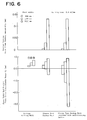
- a controllable range of a sheet crown including a common 4-stage rolling mill was compared in detail through numerical calculation.
- a sheet crown is represented here by the following numerical values.
- Results of calculation are shown in Fig. 6.
- the respective rolling mill types are indicated along the abscissa, and three types of rolling mills including a 4-stage rolling mill, a sleeve-roll type backup roll rolling mill and further a sleeve-roll type backup roll rolling mill provided with a roll-crossing device according to the present invention, were compared.
- a lower half of Fig. 6 shows a controllable range of a sheet crown C2 in the sheet width end portion, while an upper half of Fig. 6 shows a control amount ⁇ C4 of a sheet crown C4 in the quarter portion.
- a crown of a sheet at the time of employing various crown control functions is shown taking the sheet crown C2 in the sheet width end portion along an ordinate and the sheet crown C4 in the quarter portion along an abscissa.
- a rhombus formed by connecting points A, B, C and D represents variation of a sheet crown when a sleeve-roll type backup roll is revolved one turn with a roll cross angle fixed at zero degree.
- a sheet crown can take any arbitrary point within a hexagon formed by connecting points A, B, B', D', C', and C.
- the quarter portion sheet crown control amount ⁇ C4 shown in the upper half of Fig. 6 is representation of a width in the direction of the abscissa of this hexagon.
- a V-shaped crown can be further added to the V-, W-, A- and M-shaped crown patterns formed by the sleeve-roll type backup rolls owing to provision of both a roll-crossing device and sleeve-roll type backup rolls, the respective crown patterns are further diversified, a sheet crown of a rolled material and complex sheet configuration defects such as composite elongations can be simultaneously controlled.
Landscapes
- Engineering & Computer Science (AREA)
- Mechanical Engineering (AREA)
- Reduction Rolling/Reduction Stand/Operation Of Reduction Machine (AREA)
- Control Of Metal Rolling (AREA)
Priority Applications (3)
| Application Number | Priority Date | Filing Date | Title |
|---|---|---|---|
| BR9304173A BR9304173A (pt) | 1993-10-07 | 1993-10-07 | Laminador |
| DE1993616752 DE69316752T2 (de) | 1993-10-08 | 1993-10-08 | Walzwerk |
| EP93116369A EP0647486B1 (fr) | 1993-10-07 | 1993-10-08 | Laminoir |
Applications Claiming Priority (2)
| Application Number | Priority Date | Filing Date | Title |
|---|---|---|---|
| BR9304173A BR9304173A (pt) | 1993-10-07 | 1993-10-07 | Laminador |
| EP93116369A EP0647486B1 (fr) | 1993-10-07 | 1993-10-08 | Laminoir |
Publications (2)
| Publication Number | Publication Date |
|---|---|
| EP0647486A1 true EP0647486A1 (fr) | 1995-04-12 |
| EP0647486B1 EP0647486B1 (fr) | 1998-01-28 |
Family
ID=25664584
Family Applications (1)
| Application Number | Title | Priority Date | Filing Date |
|---|---|---|---|
| EP93116369A Revoked EP0647486B1 (fr) | 1993-10-07 | 1993-10-08 | Laminoir |
Country Status (2)
| Country | Link |
|---|---|
| EP (1) | EP0647486B1 (fr) |
| BR (1) | BR9304173A (fr) |
Cited By (1)
| Publication number | Priority date | Publication date | Assignee | Title |
|---|---|---|---|---|
| CN117564084A (zh) * | 2024-01-17 | 2024-02-20 | 太原科技大学 | 镁合金板材及改善其各向异性的异步角轧组合轧制工艺 |
Families Citing this family (1)
| Publication number | Priority date | Publication date | Assignee | Title |
|---|---|---|---|---|
| DE59912592D1 (de) * | 1998-03-09 | 2006-02-09 | Sms Demag Ag | Führungselement einer Stranggiessanlage |
Citations (7)
| Publication number | Priority date | Publication date | Assignee | Title |
|---|---|---|---|---|
| JPS5725206A (en) * | 1980-07-21 | 1982-02-10 | Sumitomo Metal Ind Ltd | Rolling mill |
| JPS61202704A (ja) * | 1985-03-07 | 1986-09-08 | Mitsubishi Heavy Ind Ltd | ロ−ルクロス式圧延機 |
| JPS61279305A (ja) * | 1985-06-06 | 1986-12-10 | Ishikawajima Harima Heavy Ind Co Ltd | 圧延機 |
| WO1990000450A1 (fr) * | 1988-07-11 | 1990-01-25 | DAVID McKEE (POOLE) LIMITED | Laminage de materiau en bande |
| CH673128A5 (en) * | 1988-07-11 | 1990-02-15 | Escher Wyss Gmbh | Pliable roller paper press - has adjustable angle between roller axes to give variety of pressures without roller change |
| JPH02284711A (ja) * | 1989-04-25 | 1990-11-22 | Mitsubishi Heavy Ind Ltd | 圧延機の分割型ロール |
| JPH03138006A (ja) * | 1989-10-25 | 1991-06-12 | Mitsubishi Heavy Ind Ltd | 分割バックアップロールを用いた圧延機 |
-
1993
- 1993-10-07 BR BR9304173A patent/BR9304173A/pt not_active IP Right Cessation
- 1993-10-08 EP EP93116369A patent/EP0647486B1/fr not_active Revoked
Patent Citations (7)
| Publication number | Priority date | Publication date | Assignee | Title |
|---|---|---|---|---|
| JPS5725206A (en) * | 1980-07-21 | 1982-02-10 | Sumitomo Metal Ind Ltd | Rolling mill |
| JPS61202704A (ja) * | 1985-03-07 | 1986-09-08 | Mitsubishi Heavy Ind Ltd | ロ−ルクロス式圧延機 |
| JPS61279305A (ja) * | 1985-06-06 | 1986-12-10 | Ishikawajima Harima Heavy Ind Co Ltd | 圧延機 |
| WO1990000450A1 (fr) * | 1988-07-11 | 1990-01-25 | DAVID McKEE (POOLE) LIMITED | Laminage de materiau en bande |
| CH673128A5 (en) * | 1988-07-11 | 1990-02-15 | Escher Wyss Gmbh | Pliable roller paper press - has adjustable angle between roller axes to give variety of pressures without roller change |
| JPH02284711A (ja) * | 1989-04-25 | 1990-11-22 | Mitsubishi Heavy Ind Ltd | 圧延機の分割型ロール |
| JPH03138006A (ja) * | 1989-10-25 | 1991-06-12 | Mitsubishi Heavy Ind Ltd | 分割バックアップロールを用いた圧延機 |
Non-Patent Citations (5)
| Title |
|---|
| PATENT ABSTRACTS OF JAPAN vol. 11, no. 140 (M - 586) 8 May 1987 (1987-05-08) * |
| PATENT ABSTRACTS OF JAPAN vol. 11, no. 34 (M - 558) 31 January 1987 (1987-01-31) * |
| PATENT ABSTRACTS OF JAPAN vol. 15, no. 354 (M - 1155) 6 September 1991 (1991-09-06) * |
| PATENT ABSTRACTS OF JAPAN vol. 15, no. 49 (M - 1078) 6 February 1991 (1991-02-06) * |
| PATENT ABSTRACTS OF JAPAN vol. 6, no. 86 (M - 131) 25 May 1982 (1982-05-25) * |
Cited By (2)
| Publication number | Priority date | Publication date | Assignee | Title |
|---|---|---|---|---|
| CN117564084A (zh) * | 2024-01-17 | 2024-02-20 | 太原科技大学 | 镁合金板材及改善其各向异性的异步角轧组合轧制工艺 |
| CN117564084B (zh) * | 2024-01-17 | 2024-04-26 | 太原科技大学 | 镁合金板材及改善其各向异性的异步角轧组合轧制工艺 |
Also Published As
| Publication number | Publication date |
|---|---|
| EP0647486B1 (fr) | 1998-01-28 |
| BR9304173A (pt) | 1995-06-06 |
Similar Documents
| Publication | Publication Date | Title |
|---|---|---|
| CN1089060C (zh) | 凸度控制支承辊组件及轧机机架和轧制中控制凸度的方法 | |
| US4289013A (en) | Crown control for rolling mill | |
| EP0647486B1 (fr) | Laminoir | |
| EP0937515B1 (fr) | Cylindre pour influencer la planéité | |
| US3528274A (en) | Roll bending | |
| JPS63101009A (ja) | 多ロ−ル圧延スタンド | |
| US5170652A (en) | Planetary rolling mill | |
| EP0584642A1 (fr) | Laminoir | |
| JP2836843B2 (ja) | 圧延機の分割型ロール | |
| JP2665006B2 (ja) | 分割バックアップロールを用いた圧延機 | |
| US20010029848A1 (en) | Adjustable crown and edge drop control back-up roll | |
| DE69316752T2 (de) | Walzwerk | |
| JP2851479B2 (ja) | 圧延機 | |
| KR960016455B1 (ko) | 압연기 | |
| JP3200992B2 (ja) | 圧延ロールの支持構造 | |
| JP3067387B2 (ja) | 圧延機 | |
| JP2977379B2 (ja) | 圧延機の分割型補強ロール | |
| JP2984504B2 (ja) | 圧延機の分割型補強ロール | |
| JP3021213B2 (ja) | スリーブ補強ロール式圧延機 | |
| JP2587511B2 (ja) | 圧延機の分割型補強ロール | |
| JPH01205805A (ja) | 分割バックアップロール式多段圧延機 | |
| JP2984477B2 (ja) | 圧延機の分割型補強ロール | |
| US3411335A (en) | Thrust bearing assembly | |
| JP2941591B2 (ja) | タンデム圧延機列 | |
| JP3007223B2 (ja) | 圧延機 |
Legal Events
| Date | Code | Title | Description |
|---|---|---|---|
| PUAI | Public reference made under article 153(3) epc to a published international application that has entered the european phase |
Free format text: ORIGINAL CODE: 0009012 |
|
| 17P | Request for examination filed |
Effective date: 19931105 |
|
| AK | Designated contracting states |
Kind code of ref document: A1 Designated state(s): DE FR GB IT |
|
| 17Q | First examination report despatched |
Effective date: 19960314 |
|
| GRAG | Despatch of communication of intention to grant |
Free format text: ORIGINAL CODE: EPIDOS AGRA |
|
| GRAH | Despatch of communication of intention to grant a patent |
Free format text: ORIGINAL CODE: EPIDOS IGRA |
|
| GRAH | Despatch of communication of intention to grant a patent |
Free format text: ORIGINAL CODE: EPIDOS IGRA |
|
| GRAA | (expected) grant |
Free format text: ORIGINAL CODE: 0009210 |
|
| AK | Designated contracting states |
Kind code of ref document: B1 Designated state(s): DE FR GB IT |
|
| REF | Corresponds to: |
Ref document number: 69316752 Country of ref document: DE Date of ref document: 19980305 |
|
| ITF | It: translation for a ep patent filed | ||
| ET | Fr: translation filed | ||
| PLBQ | Unpublished change to opponent data |
Free format text: ORIGINAL CODE: EPIDOS OPPO |
|
| PLBI | Opposition filed |
Free format text: ORIGINAL CODE: 0009260 |
|
| PLBF | Reply of patent proprietor to notice(s) of opposition |
Free format text: ORIGINAL CODE: EPIDOS OBSO |
|
| 26 | Opposition filed |
Opponent name: SMS SCHLOEMANN-SIEMAG AG Effective date: 19981024 |
|
| PLBF | Reply of patent proprietor to notice(s) of opposition |
Free format text: ORIGINAL CODE: EPIDOS OBSO |
|
| PLBF | Reply of patent proprietor to notice(s) of opposition |
Free format text: ORIGINAL CODE: EPIDOS OBSO |
|
| PLBO | Opposition rejected |
Free format text: ORIGINAL CODE: EPIDOS REJO |
|
| APAC | Appeal dossier modified |
Free format text: ORIGINAL CODE: EPIDOS NOAPO |
|
| APAE | Appeal reference modified |
Free format text: ORIGINAL CODE: EPIDOS REFNO |
|
| APAC | Appeal dossier modified |
Free format text: ORIGINAL CODE: EPIDOS NOAPO |
|
| PGFP | Annual fee paid to national office [announced via postgrant information from national office to epo] |
Ref country code: GB Payment date: 20011010 Year of fee payment: 9 Ref country code: FR Payment date: 20011010 Year of fee payment: 9 |
|
| REG | Reference to a national code |
Ref country code: GB Ref legal event code: IF02 |
|
| PLAB | Opposition data, opponent's data or that of the opponent's representative modified |
Free format text: ORIGINAL CODE: 0009299OPPO |
|
| R26 | Opposition filed (corrected) |
Opponent name: SMS DEMAG AG Effective date: 19981024 |
|
| PGFP | Annual fee paid to national office [announced via postgrant information from national office to epo] |
Ref country code: DE Payment date: 20021011 Year of fee payment: 10 |
|
| APAC | Appeal dossier modified |
Free format text: ORIGINAL CODE: EPIDOS NOAPO |
|
| RDAH | Patent revoked |
Free format text: ORIGINAL CODE: EPIDOS REVO |
|
| RDAG | Patent revoked |
Free format text: ORIGINAL CODE: 0009271 |
|
| STAA | Information on the status of an ep patent application or granted ep patent |
Free format text: STATUS: PATENT REVOKED |
|
| 27W | Patent revoked |
Effective date: 20030119 |
|
| GBPR | Gb: patent revoked under art. 102 of the ep convention designating the uk as contracting state |
Free format text: 20030119 |
|
| APAH | Appeal reference modified |
Free format text: ORIGINAL CODE: EPIDOSCREFNO |