EP0647732A1 - Métier à tricoter circulaire et dispositif de palier pour celui-ci - Google Patents
Métier à tricoter circulaire et dispositif de palier pour celui-ci Download PDFInfo
- Publication number
- EP0647732A1 EP0647732A1 EP94116051A EP94116051A EP0647732A1 EP 0647732 A1 EP0647732 A1 EP 0647732A1 EP 94116051 A EP94116051 A EP 94116051A EP 94116051 A EP94116051 A EP 94116051A EP 0647732 A1 EP0647732 A1 EP 0647732A1
- Authority
- EP
- European Patent Office
- Prior art keywords
- race
- bed
- base
- tracks
- knitting machine
- Prior art date
- Legal status (The legal status is an assumption and is not a legal conclusion. Google has not performed a legal analysis and makes no representation as to the accuracy of the status listed.)
- Granted
Links
- 238000009940 knitting Methods 0.000 title claims abstract description 79
- 238000001816 cooling Methods 0.000 claims abstract description 21
- 238000010438 heat treatment Methods 0.000 claims abstract description 21
- 238000010276 construction Methods 0.000 description 3
- 239000000463 material Substances 0.000 description 2
- 229910045601 alloy Inorganic materials 0.000 description 1
- 239000000956 alloy Substances 0.000 description 1
- 230000002401 inhibitory effect Effects 0.000 description 1
- 238000003754 machining Methods 0.000 description 1
- 229910052751 metal Inorganic materials 0.000 description 1
- 239000002184 metal Substances 0.000 description 1
- 150000002739 metals Chemical class 0.000 description 1
- 230000004048 modification Effects 0.000 description 1
- 238000012986 modification Methods 0.000 description 1
- 230000036316 preload Effects 0.000 description 1
Images


Classifications
-
- F—MECHANICAL ENGINEERING; LIGHTING; HEATING; WEAPONS; BLASTING
- F16—ENGINEERING ELEMENTS AND UNITS; GENERAL MEASURES FOR PRODUCING AND MAINTAINING EFFECTIVE FUNCTIONING OF MACHINES OR INSTALLATIONS; THERMAL INSULATION IN GENERAL
- F16C—SHAFTS; FLEXIBLE SHAFTS; ELEMENTS OR CRANKSHAFT MECHANISMS; ROTARY BODIES OTHER THAN GEARING ELEMENTS; BEARINGS
- F16C19/00—Bearings with rolling contact, for exclusively rotary movement
- F16C19/02—Bearings with rolling contact, for exclusively rotary movement with bearing balls essentially of the same size in one or more circular rows
- F16C19/14—Bearings with rolling contact, for exclusively rotary movement with bearing balls essentially of the same size in one or more circular rows for both radial and axial load
- F16C19/16—Bearings with rolling contact, for exclusively rotary movement with bearing balls essentially of the same size in one or more circular rows for both radial and axial load with a single row of balls
- F16C19/163—Bearings with rolling contact, for exclusively rotary movement with bearing balls essentially of the same size in one or more circular rows for both radial and axial load with a single row of balls with angular contact
-
- D—TEXTILES; PAPER
- D04—BRAIDING; LACE-MAKING; KNITTING; TRIMMINGS; NON-WOVEN FABRICS
- D04B—KNITTING
- D04B9/00—Circular knitting machines with independently-movable needles
-
- D—TEXTILES; PAPER
- D04—BRAIDING; LACE-MAKING; KNITTING; TRIMMINGS; NON-WOVEN FABRICS
- D04B—KNITTING
- D04B15/00—Details of, or auxiliary devices incorporated in, weft knitting machines, restricted to machines of this kind
-
- D—TEXTILES; PAPER
- D04—BRAIDING; LACE-MAKING; KNITTING; TRIMMINGS; NON-WOVEN FABRICS
- D04B—KNITTING
- D04B15/00—Details of, or auxiliary devices incorporated in, weft knitting machines, restricted to machines of this kind
- D04B15/14—Needle cylinders
-
- D—TEXTILES; PAPER
- D04—BRAIDING; LACE-MAKING; KNITTING; TRIMMINGS; NON-WOVEN FABRICS
- D04B—KNITTING
- D04B35/00—Details of, or auxiliary devices incorporated in, knitting machines, not otherwise provided for
-
- F—MECHANICAL ENGINEERING; LIGHTING; HEATING; WEAPONS; BLASTING
- F16—ENGINEERING ELEMENTS AND UNITS; GENERAL MEASURES FOR PRODUCING AND MAINTAINING EFFECTIVE FUNCTIONING OF MACHINES OR INSTALLATIONS; THERMAL INSULATION IN GENERAL
- F16C—SHAFTS; FLEXIBLE SHAFTS; ELEMENTS OR CRANKSHAFT MECHANISMS; ROTARY BODIES OTHER THAN GEARING ELEMENTS; BEARINGS
- F16C25/00—Bearings for exclusively rotary movement adjustable for wear or play
- F16C25/06—Ball or roller bearings
- F16C25/08—Ball or roller bearings self-adjusting
-
- F—MECHANICAL ENGINEERING; LIGHTING; HEATING; WEAPONS; BLASTING
- F16—ENGINEERING ELEMENTS AND UNITS; GENERAL MEASURES FOR PRODUCING AND MAINTAINING EFFECTIVE FUNCTIONING OF MACHINES OR INSTALLATIONS; THERMAL INSULATION IN GENERAL
- F16C—SHAFTS; FLEXIBLE SHAFTS; ELEMENTS OR CRANKSHAFT MECHANISMS; ROTARY BODIES OTHER THAN GEARING ELEMENTS; BEARINGS
- F16C33/00—Parts of bearings; Special methods for making bearings or parts thereof
- F16C33/30—Parts of ball or roller bearings
- F16C33/58—Raceways; Race rings
- F16C33/60—Raceways; Race rings divided or split, e.g. comprising two juxtaposed rings
- F16C33/61—Raceways; Race rings divided or split, e.g. comprising two juxtaposed rings formed by wires
-
- F—MECHANICAL ENGINEERING; LIGHTING; HEATING; WEAPONS; BLASTING
- F16—ENGINEERING ELEMENTS AND UNITS; GENERAL MEASURES FOR PRODUCING AND MAINTAINING EFFECTIVE FUNCTIONING OF MACHINES OR INSTALLATIONS; THERMAL INSULATION IN GENERAL
- F16C—SHAFTS; FLEXIBLE SHAFTS; ELEMENTS OR CRANKSHAFT MECHANISMS; ROTARY BODIES OTHER THAN GEARING ELEMENTS; BEARINGS
- F16C2300/00—Application independent of particular apparatuses
- F16C2300/10—Application independent of particular apparatuses related to size
- F16C2300/14—Large applications, e.g. bearings having an inner diameter exceeding 500 mm
-
- Y—GENERAL TAGGING OF NEW TECHNOLOGICAL DEVELOPMENTS; GENERAL TAGGING OF CROSS-SECTIONAL TECHNOLOGIES SPANNING OVER SEVERAL SECTIONS OF THE IPC; TECHNICAL SUBJECTS COVERED BY FORMER USPC CROSS-REFERENCE ART COLLECTIONS [XRACs] AND DIGESTS
- Y10—TECHNICAL SUBJECTS COVERED BY FORMER USPC
- Y10S—TECHNICAL SUBJECTS COVERED BY FORMER USPC CROSS-REFERENCE ART COLLECTIONS [XRACs] AND DIGESTS
- Y10S384/00—Bearings
- Y10S384/90—Cooling or heating
- Y10S384/905—Temperature compensation
Definitions
- This invention relates to a circular knitting machine, and more particularly to a circular knitting machine having a needle cylinder rotatably mounted to a bed member for rotation thereof about the bed member.
- Circular knitting machines are generally considered a high precision type of knitting machine.
- Some types of conventional circular knitting machines have a needle cylinder which includes a cylinder base.
- the cylinder base is conventionally seated in a generally L-shaped bed and is supported in a rotatable manner by a bearing assembly that is positioned between the cylinder base and the L-shaped bed.
- the bearing assembly conventionally includes pairs of annular wire tracks and a plurality of ball bearings mounted between the pairs of wire tracks.
- the needle cylinder increases in temperature particularly because the knitting tools which are guided in the needle cylinder perform rapid upward and downward movements. As the temperature in the needle cylinder increases, the heat formed therein is transferred from the needle cylinder to the cylinder base causing thermal expansion in and around the cylinder base. When the machine is stopped, however, the ambient atmosphere often cools the cylinder base. A distortion occurs which is caused by these temperature changes, i.e., temperature differential. This distortion substantially affects the machine's accuracy.
- the circular knitting machine has an elastic support flange that moves the position of one of the circular wire tracks of a pair thereof responsive to pressure fluctuation (i.e., caused by the thermal expansion of the cylinder base) between the circular wire track and ball bearings.
- Another non-elastic support flange of the other corresponding circular wire track is anchored in such a way as to cooperate with the elastic support flange. The spacing between the wire tracks of the pair is increased and the wire tracks slide outwardly on the ball bearings. The thermal expansion of the cylinder base is thus compensated.
- An object of the present invention is to provide a more accurate circular knitting machine by compensating for thermal expansion in and around a cylinder base of a needle cylinder of the machine.
- the invention meets these and other objects by providing a circular knitting machine that has a bed member and a needle cylinder including a cylinder base rotatably mounted to the bed member.
- the knitting machine also has a bearing assembly positioned between the bed member and the cylinder base for rotatable mounting of the bed member to the cylinder base.
- the bearing assembly preferably includes a first race slidably connected to either the cylinder base or the bed member and a second race connected to either the cylinder base or the bed member and positioned adjacent and spaced-apart from the first race.
- First and second tracks are respectively mounted to the first and second races, and bearings are positionally supported by and between the first and second tracks so that the cylinder base freely rotates about the bed member.
- Thermal-expansion compensating means is preferably integrally formed with either the cylinder base or the bed member and is positioned closely adjacent the race respectively connected to either the cylinder base or the bed member.
- the compensating means is adapted for compensating for thermal expansion in the cylinder base during heating and cooling thereof.
- the compensating means preferably includes a flexible flange integrally formed with either the cylinder base or the bed member and positioned closely adjacent the corresponding race.
- the race positioned closely adjacent the flexible flange is preferably slidably connected to the corresponding cylinder base or bed member so that slidable movement of the corresponding race responsive to heating and cooling of the cylinder base thereby moves the flexible flange.
- This configuration of the circular knitting machine and the bearing assembly positioned therein advantageously lessens the tension on the bearing assembly and provides a more accurate circular knitting machine by compensating for thermal expansion in and around the cylinder base.
- the bearing assembly does not require an excessive load or tension for smooth and accurate operation.
- the present invention includes a bearing assembly adapted for connecting to and positioning between a bed member and a base of a needle cylinder of a circular knitting machine.
- the bearing assembly preferably has a first non-flexible race adapted to slidably connect to either a base of a needle cylinder or a bed member of a circular knitting machine and a second non-flexible race adapted to connect to either a base of a needle cylinder or a bed member of a circular knitting machine.
- the second race is positioned adjacent and spaced-apart from the first race.
- the first and second races each have an opposingly facing channel positioned therein. First and second spaced-apart pairs of tracks are respectively positioned in the channel of the first race and in the channel of the second race.
- a plurality of bearing balls preferably are positionally supported by and between the first and second pairs of tracks so that the base of the needle cylinder freely rotates about the bed member.
- Thermal-expansion compensating means is integrally formed with either the base of the needle cylinder or the bed member and positioned closely adjacent either the first or second corresponding race for compensating for thermal expansion in the base during heating and cooling thereof.
- the compensating means preferably includes a connector slidably connecting either the first or second race to either the base or the bed member and a flexible flange integrally formed with the base and positioned closely adjacent the second race so that the second race slidably moves responsive to heating and cooling of the base of the needle cylinder and thereby moves the flexible flange.
- the thermal expansion of the cylinder base is therefore indirectly compensated by the position of and the movement of the flexible flange.
- FIG. 1 illustrates a side sectional view of a circular knitting machine ( 20 ) according to a first embodiment of the present invention.
- the circular knitting machine ( 20 ) has a frame which includes a yarn-feed frame support member ( 25 ) and a sinker frame support member ( 26 ).
- the yarn-feed frame support member ( 25 ) supports a yarn-feed assembly ( 29 ) as illustrated.
- the sinker frame support member ( 26 ) is preferably connected to a bed member ( 30 ) by a ring plate ( 27 ) and a fastener, such as a screw ( 28 ).
- the sinker frame support member ( 26 ) also likewise supports a sinker assembly which conventionally includes sinkers ( 21 ) and sinker cams ( 22 ) positioned to operationally engage the sinkers ( 21 ).
- the sinkers ( 21 ) and the sinker cams ( 22 ) are supported on the sinker frame support member ( 26 ) by a sinker support ring ( 23 ) and a sinker ring plate ( 25 ) respectively connected to the sinker cams ( 22 ) and the sinker frame support member ( 26 ) as illustrated.
- the circular knitting machine ( 20 ) also includes a needle cylinder ( 60 ) rotatably mounted on a cylinder base ( 40 ).
- the needle cylinder ( 60 ) has vertical grooves in the outer periphery thereof in which there are slidably mounted needles ( 61 ). Butts ( 62 ) on the needles ( 61 ) operationally engage needle cams ( 64 ).
- the needle cams ( 64 ) are mounted on a cam plate member ( 65 ) which in turn is mounted on a cam support ring ( 67 ) by a fastener, such as a screw ( 62 ).
- the present invention is more particularly directed to the needle cylinder ( 60 ) and the cylinder base ( 40 ) of the circular knitting machine ( 20 ) and the accuracy problems associated with a conventional circular knitting machine when in operation.
- the construction and operational characteristics of the yarn-feed assembly ( 29 ), the sinkers ( 21 ), the needle cylinder ( 60 ), and the needles ( 61 ) are known to those skilled in the art. Accordingly, for brevity purposes, the remaining description will be directed to the needle cylinder ( 60 ), the cylinder base ( 40 ), and the rotatable mounting of the cylinder base ( 40 ) on the bed member ( 30 ) of the circular knitting machine ( 20 ).
- the cylinder base ( 40 ) of the needle cylinder ( 60 ) is preferably rotatably mounted to the bed member ( 30 ).
- the bed member ( 30 ) is preferably supported by the frame of the circular knitting machine ( 20 ), has a generally L-shape as illustrated, and includes a bed body ( 31 ) and a generally horizontal extending bed leg member ( 35 ).
- the cylinder base ( 40 ) likewise preferably has a base body ( 45 ) and a generally horizontal extending base leg member ( 41 ) preferably mounted in a rotatable manner to the bed leg member ( 35 ) as illustrated so that the cylinder base ( 40 ) rotates about the bed member ( 30 ).
- the needle cylinder ( 60 ) is preferably secured to the cylinder base body ( 45 ) by means of fasteners such as a bolt or screw ( 62 ).
- the cylinder base leg member ( 45 ) also has an engraved gear ( 42 ) connected to an outer end thereof and is preferably driven by a drive source positioned outside of the knitting machine ( 20 ) such as through a pinion (not shown).
- the needle cylinder ( 60 ) When a circular knitting machine ( 20 ) is in operation, the needle cylinder ( 60 ) often increases in temperature particularly because the needles ( 61 ) mounted in the needle cylinder ( 60 ) performs rapid upward and downward movements. As the temperature in the needle cylinder ( 60 ) increases, the heat formed therein is transferred from the needle cylinder ( 60 ) to the cylinder base ( 40 ) causing thermal expansion in and around the cylinder base ( 40 ). When the machine ( 20 ) is stopped, however, the ambient atmosphere often cools the cylinder base ( 40 ). A distortion often occurs which is caused by these temperature changes, i.e., temperature differential. This distortion substantially affects the machine's accuracy.
- a bearing assembly ( 70 ) preferably connects to, is integrally formed with, and is positioned between the cylinder base ( 40 ) and the bed member ( 30 ) as illustrated by the various embodiments in Figures 1-15.
- the bearing assembly ( 70 ) is adapted and constructed to particularly compensate for thermal expansion in and around the cylinder base ( 40 ) by including means for compensating for this thermal expansion.
- the bearing assembly ( 70 ) On a lower end of the base leg member ( 45 ) of the cylinder base ( 40 ), the bearing assembly ( 70 ) has a portion of thermal expansion compensating means illustrated in the form of a flexible annular base flange ( 43 ) which is preferably integrally formed with the cylinder base ( 40 ).
- this flexible annular base flange ( 43 ) may vary and fluctuate according to the material of the base flange ( 43 ) and/or other factors. An optimum value for this thickness, therefore, is preferably experimentally determined for the machines ( 20 ).
- the bearing assembly also preferably includes a first non-flexible annular race ( 71 ).
- the first race ( 71 ) is preferably slidably connected to the base leg member ( 45 ) and is positioned closely adjacent the flexible annular base flange ( 43 ).
- a second non-flexible annular race ( 72 ) is preferably formed integral with the bed member ( 30 ) and extends upwardly from the bed leg member ( 35 ).
- the bearing assembly ( 80 ) also preferably includes a plurality of annular wire tracks ( 81a - 81d ), i.e., four wire tracks arranged in opposing first and second pairs as illustrated, and a plurality of bearing balls ( 83 ) positioned between the wire tracks ( 81a - 81d ).
- first and second pairs of tracks are described as wire tracks, it will be understood by those skilled in the art that these tracks may be formed of various metals and alloys thereof as well as various polymeric materials and the like.
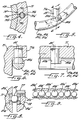
- Figures 2-4 also illustrate the connecting of the first race ( 71 ) to the cylinder base ( 40 ).
- the configuration of the first race ( 71 ) and the connecting of the race ( 71 ) to the cylinder base ( 40 ) also form portions of the thermal expansion compensating means of the bearing assembly ( 70 ).
- the cylinder base ( 40 ) and the first race ( 71 ) are slidably connected to each other in a separable manner by means of a plurality of connecting pins ( 75 ) (as best shown in Figures 2 and 3).
- Figure 4 illustrates a sectional view of the cylinder base ( 40 ) and the first race ( 71 ) slidably connected thereto taken along line 4-4 of Figure 2.
- the first race ( 71 ) is detachably connected to the cylinder base ( 40 ) so that heat is not easily transmitted from the cylinder base ( 40 ) to the first race ( 71 ).
- each of the connecting pins ( 75 ) preferably has a cylindrical upper end portion ( 75a ) and a lower end portion having a first pair of relatively flat and parallel sides ( 75b ), i.e., cut-away portions, and a second pair of arcuate sides ( 75c ).
- the base leg member ( 41 ) of the cylinder base ( 40 ) preferably has a bore positioned therein, and the first race ( 71 ) likewise has a bore positioned therein.
- These bores preferably have a generally similar-sized circumference and are preferably positionally aligned so that the upper portion ( 75b ) of the connecting pin ( 75 ) is positioned within the bore of the base leg member ( 41 ) and the lower portion is positioned within the bore of the first race ( 71 ).
- the lower portion of the connecting pin ( 75 ) also preferably has a smaller circumference than the upper portion ( 75a ).
- the connecting pins ( 75 ) are therefore installed in such a way as to provide radial spaces ( 75d ) as best illustrated in Figure 4.
- the first race ( 71 ) Preferably surrounding the parallel and arcuate sides ( 75b, 75c ) of the lower portion of the pin ( 75 ), the first race ( 71 ) also provides a small gap or slightly enlarged portion of the bore illustrated by the circle surrounding the pin ( 75 ). This small gap in combination with the radial spaces ( 75d ) allows the first race ( 71 ) to slidably move inward when the cylinder base ( 40 ) expands by heat. Because the cylinder base ( 40 ) is connected by means of the connecting pins ( 75 ), it rotates together with the first race ( 71 ).
- Figure 2 also illustrates that the bearing assembly ( 70 ) preferably has a plurality of bearing balls ( 83 ) and annular wire tracks ( 81a, 81b, 81c, 81d ).
- the bearing balls ( 83 ) are supported by the annular wire tracks ( 81a - 81d ) and preferably form first and second pairs.
- a first pair of the annular wire tracks ( 81a, 81b ) is accommodated within a concave groove or channel ( 73 ) of the first race ( 71 ), and the other pair of annular wire tracks ( 81c, 81d ) is accommodated within a concave groove or channel ( 74 ) of the second race ( 72 ) respectively as illustrated.
- the contact points between the bearing balls ( 83 ) and the annular wire tracks ( 81a - 81d ) are preferably chamfered (not shown) so as to accommodate the arcuate portions of the bearing balls ( 83 ).
- the second race ( 72 ) also preferably includes a body portion integrally formed with the bed leg member ( 35 ) of the bed member ( 30 ).
- the body portion has a lower flange positioned along a lower end of the channel ( 74 ) of the second race ( 72 ), and an upper flange member ( 77 ) is preferably mounted with a fastener such as a screw ( 76 ) for spacing or gap adjustment of the annular wire tracks ( 81c, 81d ).
- Portions of the upper flange member ( 77 ) are positioned along the upper end of the channel ( 74 ).
- the fastener is adapted for adjusting the position of the second pair of wire tracks ( 81c, 81d ) within the channel ( 74 ).
- the fastener ( 176, 276 ) may also extend to and through a body portion of the second race ( 172, 272 ) and extend to and through the bed leg member ( 135, 235 ) of the bed member ( 30 ) for providing easier access to adjustably position the second pair of wire tracks ( 81c, 81d ) and the spacing therebetween, i.e., gaps.
- the fasteners ( 176, 276 ) are illustrated in the form of a threaded bolt which screws into a threaded portion formed in the lower portion of the bed ( 30 ).
- the bolt ( 176, 276 ) is also positioned through the upper flange member ( 177, 277 ) and is fastened with a nut.
- the gaps are preferably adjusted by loosening the nut and rotating a lower end of the bolt.
- the bearing assembly ( 70 ) also preferably includes stopping means respectively mounted to the first and second races ( 71, 72 ) and contactingly engaging each of the wire tracks ( 81a - 81d ).
- the stopping means is illustrated in the form of two opposing ends of the annular wire tracks ( 81a - 81d ).
- Each wire track ( 81a - 81d ) preferably has a relatively flat first end ( 81e ) of generally the same circumference and shape as the respective wire track ( 81a - 81d ) and a cut-away portion ( 81f ) on a second end.
- an engaging pin ( 84 ) contactingly engages therewith.
- An upper end portion of the engaging pin ( 84 ) is mounted to a portion ( 71a ) of the race that accommodates the annular wire tracks ( 81a - 81d ) such as the first race ( 71 ) illustrated. Therefore, a sliding motion of the annular wire tracks ( 81a - 81d ) which is possibly generated along with the rotation of the machine ( 20 ) (indicated by the arrow in Figure 7) is stopped by the engaging pin ( 84 ).
- thermal expansion compensating means i.e., thermal expansion compensator
- the heat of the needle cylinder ( 60 ) that occurs during the operation of the knitting machine ( 20 ) is transmitted to the cylinder base ( 40 ) causing it to thermally expand.
- the thermal expansion of the cylinder base ( 40 ) is inhibited by the second non-flexible race ( 72 ) of the bearing assembly ( 70 ).
- the expansion of the cylinder base ( 40 ) thus inhibited then presses the first race ( 71 ) inward responsive thereto.
- the pressed first race ( 71 ) slidably moves about the connecting pins ( 75 ) responsive to the heating and cooling of the cylinder base ( 40 ) and then distorts the flexible annular base flange ( 43 ) of the cylinder base ( 40 ) inward. This distortion compensates for the thermal expansion of the cylinder base ( 40 ).
- This configuration and construction of the first non-flexible race ( 71 ) and the second non-flexible race ( 72 ) of the bearing assembly ( 70 ) of the present invention helps maintain the accuracy of the circular knitting machine ( 20 ) by indirectly compensating for the thermal expansion in and around the cylinder base ( 40 ). This configuration also lessens the load on the bearing assembly ( 70 ). In other words, the bearing assembly ( 70 ) does not require an excessive load or tension for smooth and accurate operation.
- Figure 8 illustrates another embodiment of a bearing assembly ( 70 ) of a circular knitting machine according to the present invention.
- the wire tracks ( 81a' - 81d' ) may have a non-circular cross-section such as the rectangular cross-sections illustrated, as well as others.
- the wire tracks ( 81a' - 81d' ) of this embodiment also preferably have chamfered portions that surface-contact the bearing balls ( 83 ) positioned therebetween.
- Figure 9 illustrates yet another embodiment of a bearing assembly ( 70 ) of a circular knitting machine according to the present invention.
- the bearing assembly ( 70 ) in this embodiment has bearings in the form of bearing balls ( 83a',83b' ) of different diameters positioned between the pair of tracks ( 81a - 81d ), and arranged alternately so as to minimize collisions between neighboring bearing balls ( 83a',83b' ).
- Figures 10-12 and 15 illustrate additional embodiments of a bearing assembly ( 70 ) of a circular knitting machine ( 20 ) according to the present invention. Like elements in these various embodiments of the bearing assembly ( 70 ) according to the present invention have been designated with prime ( ' ) or double-prime ( '' ) notation throughout.
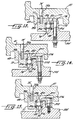
- Figure 10 illustrates a side sectional view of a bearing assembly ( 70 ) according to a fourth embodiment of the present invention.
- the fourth embodiment differs from the first embodiment in that the fourth embodiment preferably has a first annular race ( 71' ) that is provided with a flexible annular flange ( 71b' ) and a cylinder base ( 40 ) that is provided with a non-flexible annular flange ( 43a' ), i.e., corresponds to the flexible annular flange ( 43' ) of the first embodiment, that abuttingly engages the first race ( 71' ).
- the first race ( 71' ) according to this embodiment is wider than the first race ( 71 ) of the first embodiment shown in Figures 1-2.
- the first race ( 71' ) is provided with a second concave groove or channel ( 79 ) extending downwardly from the base leg member ( 41 ) of the cylinder base ( 40 ) as illustrated and positioned between the flexible annular flange ( 71b' ) and the connecting pins ( 75 ).
- the first race ( 71' ) slidably moves about the connecting pin ( 75 ) and presses against the non-flexible flange ( 43' ) of the cylinder base ( 40 ).
- the second race ( 72 ) and the connecting pins ( 10 ) are preferably of the same configurations as those in the first embodiment.
- Figures 11 and 12 respectively illustrate side sectional views of a bearing assembly ( 70 ) according to fifth and sixth embodiments of the present invention. These embodiments differ from the first and fourth embodiments in that these embodiments illustrate a relatively switched mounting position of the first and second races ( 71, 72 ) of the first and fourth embodiments.
- the first races ( 71'' ) each have a generally similar configuration and are integrally formed with the cylinder base ( 40 ) in a similar manner as the second races ( 72 ) of the first and fourth embodiments.
- the second races ( 72', 72'' ) are slidably connected to the bed member ( 30 ) in a similar manner as the first races ( 71, 71' ) of the first and fourth embodiments.
- a flexible annular flange ( 39 ) is preferably integrally formed with the bed leg member ( 35' ) in the fifth embodiment and a non-flexible annular flange ( 39' ) is integrally formed with the bed leg member in the sixth embodiment.
- the portions of the bearing assembly ( 70 ) of these embodiments are generally the same as the first and fourth embodiments and are not described further for brevity purposes. In other words, the relative positions of the first race ( 71, 71' ), the second race ( 72 ), and the flexible annular flange ( 43 ) of the first and fourth embodiments are respectively switched or are in opposite positions from these fifth and sixth embodiments.
- Figures 14 and 15 respectively illustrate side sectional views of a bearing assembly ( 70 ) according to eighth and ninth embodiments of the present invention.
- the second races ( 272, 372 ) of the bearing assembly ( 70 ) have a different construction as illustrated.
- the second races ( 272, 372 ) of these embodiments have an upper flange member ( 277, 377 ) which includes a generally L-shaped section so that the body portion of the second race ( 272, 372 ) is relatively thinner than the second races ( 72, 72', 72'', 172 ) of the other embodiments.
- the upper flange member ( 277, 377 ) of the eighth and ninth embodiments has a fastener ( 276, 376 ) that extends through the upper flange member ( 277, 377 ) and may extend only into the bed leg member ( 335 ) or may extend through the bed leg member ( 235 ) of the bed member ( 30 ) as illustrated.
Landscapes
- Engineering & Computer Science (AREA)
- General Engineering & Computer Science (AREA)
- Textile Engineering (AREA)
- Mechanical Engineering (AREA)
- Knitting Machines (AREA)
- Rolling Contact Bearings (AREA)
- Looms (AREA)
Applications Claiming Priority (2)
| Application Number | Priority Date | Filing Date | Title |
|---|---|---|---|
| JP280211/93 | 1993-10-12 | ||
| JP5280211A JPH07109646A (ja) | 1993-10-12 | 1993-10-12 | 丸編機のシリンダー基筒部におけるベアリング装置 |
Publications (2)
| Publication Number | Publication Date |
|---|---|
| EP0647732A1 true EP0647732A1 (fr) | 1995-04-12 |
| EP0647732B1 EP0647732B1 (fr) | 1999-03-10 |
Family
ID=17621867
Family Applications (1)
| Application Number | Title | Priority Date | Filing Date |
|---|---|---|---|
| EP94116051A Expired - Lifetime EP0647732B1 (fr) | 1993-10-12 | 1994-10-12 | Métier à tricoter circulaire et dispositif de palier pour celui-ci |
Country Status (6)
| Country | Link |
|---|---|
| US (1) | US5493876A (fr) |
| EP (1) | EP0647732B1 (fr) |
| JP (1) | JPH07109646A (fr) |
| KR (1) | KR100288643B1 (fr) |
| DE (1) | DE69416925T2 (fr) |
| ES (1) | ES2130326T3 (fr) |
Cited By (6)
| Publication number | Priority date | Publication date | Assignee | Title |
|---|---|---|---|---|
| EP1016747A3 (fr) * | 1998-12-21 | 2001-01-24 | Precision Fukuhara Works, Ltd. | Système de récupération d'huile pour un métier à tricoter circulaire |
| WO2002053816A1 (fr) * | 2000-12-29 | 2002-07-11 | Amtek, Spol. S R.O. | Machine a tricoter circulaire |
| GB2371564A (en) * | 2001-01-24 | 2002-07-31 | Pai Lung Machinery Mill Co Ltd | Transmission adjustment mechanism for the bearing of a circular knitting machine |
| EP2224047A1 (fr) * | 2009-02-26 | 2010-09-01 | Groz-Beckert KG | Tête de tricotage pour une machine à tricoter |
| EP3670948A1 (fr) * | 2018-12-21 | 2020-06-24 | thyssenkrupp rothe erde Germany GmbH | Palier à roulement pourvu de bague d'arrêt radiale permettant de limiter la déformation radiale du palier à roulement |
| CN111534913A (zh) * | 2020-04-27 | 2020-08-14 | 泉州市甲申九鼎机械有限公司 | 一种高速双面针织大圆机的下针筒传动装置 |
Families Citing this family (9)
| Publication number | Priority date | Publication date | Assignee | Title |
|---|---|---|---|---|
| DE10018841B4 (de) * | 2000-04-14 | 2012-07-05 | Sipra Patententwicklungs- Und Beteiligungsgesellschaft Mbh | Rundstrickmaschine |
| SG96193A1 (en) * | 2001-01-29 | 2003-05-23 | Pai Lung Machinery Mill Co Ltd | Adjustment structure of press ring and steel ring for circular knitting machine |
| KR20020068878A (ko) * | 2001-02-23 | 2002-08-28 | 파이 룽 머시너리 밀 코포레이션 리미티드 | 원형 편물기의 프레스 링과 스틸 링의 조정 구조 |
| CN100432313C (zh) * | 2003-10-20 | 2008-11-12 | 大渝机械(厦门)有限公司 | 圆编织机的鞍座调整固定装置 |
| US20070116394A1 (en) * | 2005-11-22 | 2007-05-24 | Thyssenkrupp - Rotek, Inc. | Slewing ring having improved inner race construction |
| DE102009011764A1 (de) * | 2009-03-04 | 2010-09-09 | Festo Ag & Co. Kg | Drehantriebsvorrichtung |
| US7793523B1 (en) | 2009-10-01 | 2010-09-14 | Innovative Designs, LLC | Circular knitting machine with bearing-stabilized cylinder |
| CN110656431B (zh) * | 2019-10-23 | 2024-06-07 | 泉州精镁科技有限公司 | 一种新型大盘齿轮结构 |
| CN111926449A (zh) * | 2020-07-21 | 2020-11-13 | 陈飞洋 | 针织机上针盖自动调整装置 |
Citations (3)
| Publication number | Priority date | Publication date | Assignee | Title |
|---|---|---|---|---|
| US4489573A (en) * | 1978-07-06 | 1984-12-25 | Terrot Strickmaschinen Gmbh | Circular knitting machine |
| DE3906773A1 (de) * | 1989-03-03 | 1990-09-06 | Terrot Strickmaschinen Gmbh | Rundstrickmaschine |
| DE4128372A1 (de) * | 1991-08-27 | 1993-03-04 | Sipra Patent Beteiligung | Rundstrickmaschine mit einem nadelzylinder und einer rippscheibe |
Family Cites Families (8)
| Publication number | Priority date | Publication date | Assignee | Title |
|---|---|---|---|---|
| CH50022A (de) * | 1910-01-19 | 1911-04-17 | Gustav Gomringer | Einrichtung zur lösbaren Befestigung eines Sensenblattes auf dem Wurf der Sense |
| US3543367A (en) * | 1968-01-29 | 1970-12-01 | Alfred E R Arnot | Wire race ball bearing manufacture |
| US3880481A (en) * | 1974-03-08 | 1975-04-29 | Keene Corp | Bearing assembly |
| CH619519A5 (fr) * | 1977-10-17 | 1980-09-30 | Confederation Helvetique Repre | |
| GB2110772B (en) * | 1981-11-28 | 1985-03-20 | Rolls Royce | Bearing assembly |
| DE3616244A1 (de) * | 1986-05-14 | 1987-11-19 | Schaeffler Waelzlager Kg | Radial-waelzlager |
| US5134863A (en) * | 1991-05-10 | 1992-08-04 | Mayer Industries, Inc. | Circular sliver knitting machine having increased carding capacity |
| US5211489A (en) * | 1992-10-07 | 1993-05-18 | The United States Of America As Represented By The Administrator Of The National Aeronautics And Space Administration | Radial spline assembly for antifriction bearings |
-
1993
- 1993-10-12 JP JP5280211A patent/JPH07109646A/ja active Pending
-
1994
- 1994-03-14 KR KR1019940004997A patent/KR100288643B1/ko not_active Expired - Fee Related
- 1994-09-28 US US08/314,145 patent/US5493876A/en not_active Expired - Fee Related
- 1994-10-12 DE DE69416925T patent/DE69416925T2/de not_active Expired - Lifetime
- 1994-10-12 ES ES94116051T patent/ES2130326T3/es not_active Expired - Lifetime
- 1994-10-12 EP EP94116051A patent/EP0647732B1/fr not_active Expired - Lifetime
Patent Citations (3)
| Publication number | Priority date | Publication date | Assignee | Title |
|---|---|---|---|---|
| US4489573A (en) * | 1978-07-06 | 1984-12-25 | Terrot Strickmaschinen Gmbh | Circular knitting machine |
| DE3906773A1 (de) * | 1989-03-03 | 1990-09-06 | Terrot Strickmaschinen Gmbh | Rundstrickmaschine |
| DE4128372A1 (de) * | 1991-08-27 | 1993-03-04 | Sipra Patent Beteiligung | Rundstrickmaschine mit einem nadelzylinder und einer rippscheibe |
Cited By (8)
| Publication number | Priority date | Publication date | Assignee | Title |
|---|---|---|---|---|
| EP1016747A3 (fr) * | 1998-12-21 | 2001-01-24 | Precision Fukuhara Works, Ltd. | Système de récupération d'huile pour un métier à tricoter circulaire |
| WO2002053816A1 (fr) * | 2000-12-29 | 2002-07-11 | Amtek, Spol. S R.O. | Machine a tricoter circulaire |
| GB2371564A (en) * | 2001-01-24 | 2002-07-31 | Pai Lung Machinery Mill Co Ltd | Transmission adjustment mechanism for the bearing of a circular knitting machine |
| GB2371564B (en) * | 2001-01-24 | 2003-10-08 | Pai Lung Machinery Mill Co Ltd | Adjustment structure of press ring and steel ring for circular knitting machine |
| EP2224047A1 (fr) * | 2009-02-26 | 2010-09-01 | Groz-Beckert KG | Tête de tricotage pour une machine à tricoter |
| US8056372B2 (en) | 2009-02-26 | 2011-11-15 | Groz-Beckert Kg | Knitting head for a knitting machine |
| EP3670948A1 (fr) * | 2018-12-21 | 2020-06-24 | thyssenkrupp rothe erde Germany GmbH | Palier à roulement pourvu de bague d'arrêt radiale permettant de limiter la déformation radiale du palier à roulement |
| CN111534913A (zh) * | 2020-04-27 | 2020-08-14 | 泉州市甲申九鼎机械有限公司 | 一种高速双面针织大圆机的下针筒传动装置 |
Also Published As
| Publication number | Publication date |
|---|---|
| EP0647732B1 (fr) | 1999-03-10 |
| US5493876A (en) | 1996-02-27 |
| JPH07109646A (ja) | 1995-04-25 |
| DE69416925D1 (de) | 1999-04-15 |
| ES2130326T3 (es) | 1999-07-01 |
| KR950011679A (ko) | 1995-05-15 |
| HK1013670A1 (en) | 1999-09-03 |
| KR100288643B1 (ko) | 2001-05-02 |
| DE69416925T2 (de) | 1999-09-16 |
Similar Documents
| Publication | Publication Date | Title |
|---|---|---|
| EP0647732B1 (fr) | Métier à tricoter circulaire et dispositif de palier pour celui-ci | |
| JP6669275B2 (ja) | ボールねじ装置 | |
| US5261750A (en) | Bearing assembly | |
| GB2029866A (en) | Circular knitting machine | |
| JPH01229160A (ja) | 複合運動案内装置 | |
| JP2895940B2 (ja) | 軸 受 | |
| KR100699633B1 (ko) | 베어링 시스템 및 전기 모터 조립체 | |
| JP3222998B2 (ja) | ボールスプライン | |
| EP2261016B1 (fr) | Presse | |
| KR20010015169A (ko) | 볼나사 및 이것을 사용한 직선운동장치 | |
| HK1013670B (en) | Circular knitting machine and bearing assembly for same | |
| US5607238A (en) | Reduced friction linear slide with rolling elements | |
| JPH0726293B2 (ja) | 丸編機のニ−ドルシリンダとシンカ−リングの熱膨張の差を補償する装置 | |
| US5586468A (en) | Table driving device | |
| EP1354087B1 (fr) | Machine a tricoter circulaire | |
| US4579396A (en) | Guiding assembly for translatorily or rotatively carrying a moving element | |
| US6652264B2 (en) | Electric injection mechanism | |
| US4482338A (en) | Torque transmitting bearing assembly for members adapted for a relative longitudinal movement and method of assembly thereof | |
| JPS6053214A (ja) | スプラインベアリング及び直線ガイド用スプラインベアリング | |
| US3186775A (en) | Slide | |
| US6393870B2 (en) | Circular knitting machine | |
| US3271826A (en) | Textile coiler tube gear mounting | |
| EP1673498A1 (fr) | Metier a tricoter circulaire double jersey | |
| JPH01288660A (ja) | 送りねじ装置 | |
| KR970005348Y1 (ko) | 이송축 전동용 볼스크루축의 프리텐션장치 |
Legal Events
| Date | Code | Title | Description |
|---|---|---|---|
| PUAI | Public reference made under article 153(3) epc to a published international application that has entered the european phase |
Free format text: ORIGINAL CODE: 0009012 |
|
| AK | Designated contracting states |
Kind code of ref document: A1 Designated state(s): DE ES GB IT |
|
| 17P | Request for examination filed |
Effective date: 19950512 |
|
| 17Q | First examination report despatched |
Effective date: 19970310 |
|
| GRAG | Despatch of communication of intention to grant |
Free format text: ORIGINAL CODE: EPIDOS AGRA |
|
| GRAG | Despatch of communication of intention to grant |
Free format text: ORIGINAL CODE: EPIDOS AGRA |
|
| GRAH | Despatch of communication of intention to grant a patent |
Free format text: ORIGINAL CODE: EPIDOS IGRA |
|
| GRAH | Despatch of communication of intention to grant a patent |
Free format text: ORIGINAL CODE: EPIDOS IGRA |
|
| GRAA | (expected) grant |
Free format text: ORIGINAL CODE: 0009210 |
|
| AK | Designated contracting states |
Kind code of ref document: B1 Designated state(s): DE ES GB IT |
|
| REF | Corresponds to: |
Ref document number: 69416925 Country of ref document: DE Date of ref document: 19990415 |
|
| ITF | It: translation for a ep patent filed | ||
| REG | Reference to a national code |
Ref country code: ES Ref legal event code: FG2A Ref document number: 2130326 Country of ref document: ES Kind code of ref document: T3 |
|
| PLBE | No opposition filed within time limit |
Free format text: ORIGINAL CODE: 0009261 |
|
| STAA | Information on the status of an ep patent application or granted ep patent |
Free format text: STATUS: NO OPPOSITION FILED WITHIN TIME LIMIT |
|
| 26N | No opposition filed | ||
| REG | Reference to a national code |
Ref country code: GB Ref legal event code: IF02 |
|
| PGFP | Annual fee paid to national office [announced via postgrant information from national office to epo] |
Ref country code: GB Payment date: 20041006 Year of fee payment: 11 |
|
| PG25 | Lapsed in a contracting state [announced via postgrant information from national office to epo] |
Ref country code: GB Free format text: LAPSE BECAUSE OF NON-PAYMENT OF DUE FEES Effective date: 20051012 |
|
| GBPC | Gb: european patent ceased through non-payment of renewal fee |
Effective date: 20051012 |
|
| PGFP | Annual fee paid to national office [announced via postgrant information from national office to epo] |
Ref country code: ES Payment date: 20081021 Year of fee payment: 15 |
|
| PGFP | Annual fee paid to national office [announced via postgrant information from national office to epo] |
Ref country code: DE Payment date: 20101029 Year of fee payment: 17 |
|
| REG | Reference to a national code |
Ref country code: ES Ref legal event code: FD2A Effective date: 20110325 |
|
| PGFP | Annual fee paid to national office [announced via postgrant information from national office to epo] |
Ref country code: IT Payment date: 20101016 Year of fee payment: 17 |
|
| PG25 | Lapsed in a contracting state [announced via postgrant information from national office to epo] |
Ref country code: ES Free format text: LAPSE BECAUSE OF NON-PAYMENT OF DUE FEES Effective date: 20110314 |
|
| PG25 | Lapsed in a contracting state [announced via postgrant information from national office to epo] |
Ref country code: ES Free format text: LAPSE BECAUSE OF NON-PAYMENT OF DUE FEES Effective date: 20091013 |
|
| PG25 | Lapsed in a contracting state [announced via postgrant information from national office to epo] |
Ref country code: DE Free format text: LAPSE BECAUSE OF NON-PAYMENT OF DUE FEES Effective date: 20120501 |
|
| REG | Reference to a national code |
Ref country code: DE Ref legal event code: R119 Ref document number: 69416925 Country of ref document: DE Effective date: 20120501 |
|
| PG25 | Lapsed in a contracting state [announced via postgrant information from national office to epo] |
Ref country code: IT Free format text: LAPSE BECAUSE OF NON-PAYMENT OF DUE FEES Effective date: 20111012 |