EP0647765A2 - Verfahren zum Perforieren eines Bohrloches unter Verwendung eines gewickelten Rohrstranges - Google Patents
Verfahren zum Perforieren eines Bohrloches unter Verwendung eines gewickelten Rohrstranges Download PDFInfo
- Publication number
- EP0647765A2 EP0647765A2 EP94306918A EP94306918A EP0647765A2 EP 0647765 A2 EP0647765 A2 EP 0647765A2 EP 94306918 A EP94306918 A EP 94306918A EP 94306918 A EP94306918 A EP 94306918A EP 0647765 A2 EP0647765 A2 EP 0647765A2
- Authority
- EP
- European Patent Office
- Prior art keywords
- coiled tubing
- gun
- tubing string
- perforating
- perforating gun
- Prior art date
- Legal status (The legal status is an assumption and is not a legal conclusion. Google has not performed a legal analysis and makes no representation as to the accuracy of the status listed.)
- Withdrawn
Links
Images


Classifications
-
- E—FIXED CONSTRUCTIONS
- E21—EARTH OR ROCK DRILLING; MINING
- E21B—EARTH OR ROCK DRILLING; OBTAINING OIL, GAS, WATER, SOLUBLE OR MELTABLE MATERIALS OR A SLURRY OF MINERALS FROM WELLS
- E21B23/00—Apparatus for displacing, setting, locking, releasing or removing tools, packers or the like in boreholes or wells
- E21B23/004—Indexing systems for guiding relative movement between telescoping parts of downhole tools
- E21B23/006—"J-slot" systems, i.e. lug and slot indexing mechanisms
-
- E—FIXED CONSTRUCTIONS
- E21—EARTH OR ROCK DRILLING; MINING
- E21B—EARTH OR ROCK DRILLING; OBTAINING OIL, GAS, WATER, SOLUBLE OR MELTABLE MATERIALS OR A SLURRY OF MINERALS FROM WELLS
- E21B23/00—Apparatus for displacing, setting, locking, releasing or removing tools, packers or the like in boreholes or wells
- E21B23/01—Apparatus for displacing, setting, locking, releasing or removing tools, packers or the like in boreholes or wells for anchoring the tools or the like
-
- E—FIXED CONSTRUCTIONS
- E21—EARTH OR ROCK DRILLING; MINING
- E21B—EARTH OR ROCK DRILLING; OBTAINING OIL, GAS, WATER, SOLUBLE OR MELTABLE MATERIALS OR A SLURRY OF MINERALS FROM WELLS
- E21B23/00—Apparatus for displacing, setting, locking, releasing or removing tools, packers or the like in boreholes or wells
- E21B23/04—Apparatus for displacing, setting, locking, releasing or removing tools, packers or the like in boreholes or wells operated by fluid means, e.g. actuated by explosion
- E21B23/042—Apparatus for displacing, setting, locking, releasing or removing tools, packers or the like in boreholes or wells operated by fluid means, e.g. actuated by explosion using a single piston or multiple mechanically interconnected pistons
-
- E—FIXED CONSTRUCTIONS
- E21—EARTH OR ROCK DRILLING; MINING
- E21B—EARTH OR ROCK DRILLING; OBTAINING OIL, GAS, WATER, SOLUBLE OR MELTABLE MATERIALS OR A SLURRY OF MINERALS FROM WELLS
- E21B43/00—Methods or apparatus for obtaining oil, gas, water, soluble or meltable materials or a slurry of minerals from wells
- E21B43/11—Perforators; Permeators
- E21B43/116—Gun or shaped-charge perforators
- E21B43/1185—Ignition systems
- E21B43/11852—Ignition systems hydraulically actuated
-
- E—FIXED CONSTRUCTIONS
- E21—EARTH OR ROCK DRILLING; MINING
- E21B—EARTH OR ROCK DRILLING; OBTAINING OIL, GAS, WATER, SOLUBLE OR MELTABLE MATERIALS OR A SLURRY OF MINERALS FROM WELLS
- E21B43/00—Methods or apparatus for obtaining oil, gas, water, soluble or meltable materials or a slurry of minerals from wells
- E21B43/11—Perforators; Permeators
- E21B43/119—Details, e.g. for locating perforating place or direction
- E21B43/1193—Dropping perforation guns after gun actuation
Definitions
- the present invention relates to a method of perforating a well utilizing perforating guns conveyed into the well on a coiled tubing string.
- tubing conveyed perforating systems for use in completing wells have been conveyed into the wells on a tubing or pipe string with the string left in position in the well during the perforating of the well.
- the perforating guns may have disintegrated or may be retrieved, or may be released or dropped from the tubing or pipe string through the use of various techniques.
- an automatically releasing gun hanger has been proposed as shown in our U.S. patent specification no. 5,156,213.
- This patent describes an automatically releasing gun hanger which is run into the well on a rigid tubing string or pipe string.
- the gun hanger is set within the well by a rotating motion of the rigid tubing string or pipe string.
- the rigid tubing string or pipe string is then disconnected from the guns attached to the gun hanger through further rotational motion.
- the pipe string can then be removed from the well.
- the perforating gun is fired by a pressure actuated firing head and upon firing of the perforating gun, the gun hanger automatically releases thus allowing the guns to drop to the bottom of the well and leaving an unobstructed flow path from the perforations up through the well bore.
- a method of perforating a casing of a well which method comprises:
- the releasable gun hanger is actuatable by reciprocating non-rotating motion
- said releasable connector is a pressure responsive releasable connector
- step (c) includes actuating said gun hanger by reciprocating motion of said coiled tubing string without rotating said coiled tubing string
- step (d) includes increasing fluid pressure in said coiled tubing string and thereby releasing said pressure responsive releasable connector from said perforating gun.
- the perforating gun has a stinger extending upward therefrom and said stinger is received in said pressure responsive releasable connector and is slidable therein between a lower open position wherein a coiled tubing bore of said coiled tubing string is open, and an upper closed position wherein said coiled tubing bore is closed; and said method further comprises between steps (b) and (c), setting down weight on said coiled tubing string to move said stinger to said upper closed position thereby closing said coiled tubing bore.
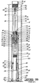
- FIG. 1 is an elevation schematic view of the prior art system of U.S. patent no. 5,156,213 showing an automatic releasing gun hanger in place within a well liner.
- the gun hanger is of the type which is set and subsequently released by rotational motion of a rigid pipe string.
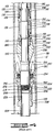
- FIGS. 2, 3 and 4 are enlarged elevational views of the prior art releasable gun hanger of U.S. patent no. 5,156,213.
- FIG. 5 is an elevation schematic sectioned view of a well using a monobore completion and using one embodiment of the coiled tubing conveyed perforating system of the present invention.
- FIG. 6 is an elevation schematic sectioned view of an alternative embodiment of the coiled tubing conveyed perforating system of the present invention in use in a well casing to be completed with conventional production tubing.
- FIG. 7 is an elevation schematic sectioned view of the system of FIG. 6 after the perforating guns have fired and dropped into the bottom of the hole and after the coiled tubing string has been removed and a production tubing string and production tubing packer have been set in place within the casing bore.
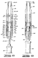
- FIGS. 8, 9 and 10 comprise a sequential series of elevation sectioned views of the pressure operated release mechanism and the upper end of the perforating gun assembly of either FIG. 5 or FIG. 6.
- FIG. 11 is a laid-out view of a portion of the automatic J-slot and lug assembly of the modified casing hanger utilized with the systems of FIGS. 5-7.
- FIG. 1 a monobore completion system is shown where the well is completed using a tubing conveyed perforating completion system having a releasable gun hanger for the tubing conveyed perforating guns.
- a well casing 10 having a liner 12 is shown in a well bore 14.
- the casing 10 and liner 12 are typically cemented in the well bore 14.
- Installed on the upper end of the liner 12 is a polished bore receptacle 16.
- the polished bore receptacle 16 may be of any suitable type, such as sold by Otis Engineering Corporation, Dallas, Texas. Additionally, the polished bore receptacle may be either installed on the upper end of the liner 12 or the lower end of the casing 10.
- a tie-back seal assembly 18 Engaging the polished bore of receptacle 16 is a tie-back seal assembly 18 having a plurality of seals 20 thereon, the tie-back seal assembly 18 being connected to the lower end of production pipe string 22.
- the tie-back seal assembly 18 may be of any suitable type such as sold by Otis Engineering Corporation, Dallas, Texas.
- FIG. 1 Further shown in FIG. 1 is a tubing conveyed perforating gun assembly 24 having a centralizer 26 thereon to centralize the perforating gun assembly 24 in the liner 12, a firing head 28 thereon, an on-off mandrel 30 on the upper end of the firing head 28, and a releasable gun hanger 32 connected to the lower end thereof.
- the on-off mandrel 30 may be of any suitable type which is capable of mating with a suitable on-off shoe (not shown) attached to the end of either a drill pipe work string (not shown) or tubing string (not shown) which is used to run the perforating gun assembly 24 having releasable gun hanger 32 thereon into the liner 12 to the desired location at which time, the perforating gun assembly 24 is installed in the liner 12 and the drill pipe work string or tubing string is disconnected from the perforating gun assembly 24 and removed from the well.
- the firing head 28 on the perforating gun assembly 24 may be of any suitable type, such as described in U. S. Patent No. 4,614,156.
- the releasable gun hanger 32 is shown in the liner 12.
- the releasable gun hanger 32 comprises an automatic gun release section 34 and support section 36. As shown in FIG. 2, the releasable gun hanger 32 has the support section 36 in its locked running position for running through the liner 12.
- the automatic gun release section 34 comprises a mandrel assembly 40, housing assembly 42 and explosive charge carrier assembly 44.
- the mandrel assembly 40 comprises upper mandrel 46 and charge carrier mandrel 48.
- the upper mandrel 46 comprises an elongated annular cylindrical member having, on the exterior thereof, first cylindrical surface 52, second cylindrical surface 54 and third cylindrical surface 56 and having, on the interior thereof, first bore 58, first threaded bore 60, second bore 62, frusto-conical bore 64, third bore 66, second threaded bore 68 and fourth bore 70.
- Charge carrier mandrel 48 comprises an elongated annular cylindrical member having, on the exterior thereof, threaded surface 72 which threadedly engages second threaded bore 68 of upper mandrel 46, first cylindrical surface 74 having, in turn, a plurality of annular recesses 76 therein containing annular elastomeric seal means 78 therein which sealingly engage fourth bore 70 of upper mandrel 46, annular recess 80 therein, third cylindrical surface 84 and having, on the interior thereof, first bore 86, blind bore 88 and threaded recess 90 on the end thereof.
- the charge carrier mandrel 48 further includes threaded aperture 92 having, in turn, set screw 94 therein and spacer sleeve 96, located on first cylindrical surface 74 of mandrel 48 and having, in turn, a plurality of apertures 98 therein.
- the charge carrier mandrel 48 is threadedly connected at its lower end to the upper end of support mandrel 200.
- the housing assembly 42 comprises upper housing 102 and lower housing 104.
- the upper housing 102 comprises an elongated annular cylindrical member having, on the exterior thereof, frusto-conical surface 106 and cylindrical surface 108 and having, on the interior thereof, first bore 110 having, in turn, annular recess 112 therein containing annular elastomeric seal means 114 therein, which, in turn, slidingly, sealing engage third cylindrical surface 56 of upper mandrel 46, second bore 116 and threaded bore 118.
- lower housing 104 comprises an elongated annular cylindrical member having, on the exterior thereof, first cylindrical surface 120 having, in turn, annular recess 122 containing annular elastomeric seal means 124 therein which, in turn, sealingly engage a portion of second bore 116 of upper housing 102, first threaded surface 126 which threadedly engages threaded bore 118 of upper housing 102, second cylindrical surface 128 and second threaded surface 130 and having, on the interior thereof, first bore 132, frusto-conical surface 134, second bore 136, third bore 138 having, in turn, annular recess 140 containing annular elastomeric seal means 142 therein, and fourth bore 144.
- the explosive charge carrier assembly 44 comprises booster holder 150, charge carrier 152, detonating cord 154 having booster 156 on one end thereof and end seal 158 on the other end thereof, and a plurality of shaped explosive charges 160.
- the booster holder 150 which is retained within second bore 62 of upper mandrel 46 comprises an annular cylindrical member having a cylindrical exterior surface 162 having annular lugs 164 thereon and bore 166 therethrough through which detonating cord 154 extends.
- Charge carrier 152 which is retained within first bore 86 of charge carrier mandrel 48 comprises an elongated annular cylindrical member having cylindrical exterior surface 168 having, in turn, fluid relief grooves 170 therein and having, on the interior thereof, threaded bore 172, threaded plug 174 therein having, in turn, bore 176 therein to receive the detonating cord 154 therethrough, bore 178 through which detonating cord 154 extends and a plurality of apertures 180 in which shaped explosive charges 160 are received.
- the charge carrier 152 is retained within charge carrier mandrel 48 by set screw 94 engaging exterior surface 168 of the carrier 152.
- the annular cavity 182 between the mandrel assembly 40 and housing assembly 42 is filled with suitable oil, such as silicon oil, to prevent substantial movement of the releasable gun hanger until actuated.
- suitable oil such as silicon oil
- the support section 36 comprises support mandrel 200, slip wedge 202, and J-slot and slip assembly 204.
- the support mandrel 200 comprises upper support mandrel 206 and slip mandrel 208.
- the upper support mandrel 206 comprises an elongated cylindrical member having an upper threaded end 210 (see FIG. 3) which threadedly engages threaded recess 90 of charge carrier mandrel 48, cylindrical seal section 212 which slidingly, sealingly engages annular elastomeric seal means 142 of lower housing 104 to seal the lower end of annular oil filled cavity 182, annular slip wedge abutment 214 and lower threaded end 216.
- the slip mandrel 208 comprises an elongated annular cylindrical member having, on the exterior thereof, cylindrical surface 218, J-slot lug 220, frusto-conical annular wedge 222, and threaded lower surface 224 and having, on the interior thereof, threaded bore 226 which threadedly engages lower threaded end 216 of upper support mandrel 206 and bore 228.
- the slip wedge 202 comprises an annular cylindrical member having, on the exterior thereof, first cylindrical surface 230, first frusto-conical annular surface 232, second cylindrical surface 234, and second frusto-conical annular slip surface 236 and having, on the interior thereof, threaded bore 240 which threadedly engages second threaded surface 130 of lower housing 104 and bore 242 through which a portion of upper support mandrel 206 extends.
- the J-slot and slip assembly 204 comprises a slip retainer housing 250 having, in turn, a plurality of cantilevered slips 252 resiliently mounted thereon by means of springs 254 which also bias the slips 252 against liner 12 and a conventional J-slot 256 in which the J-slot lug 220 on slip mandrel 208 moves to allow the setting of the releasable gun hanger 32 in the liner 12.
- the J-slot and slip housing 250 includes a central bore 260 and frusto-conical annular abutment surface 262.
- the J-slot and slip assembly 204 and slip mandrel 208 can be of any conventional, commercially available type, such as sold by Baker Hughes, Inc., Houston, Texas.
- the well bore is drilled and has the casing 10 and liner 12 typically cemented therein having either the liner 12 or casing 10 having, in turn, the polished bore receptacle 16 installed thereon.
- the production pipe string 22 having the seal assembly 18 on the end thereof is run into the casing 10 with the seal assembly 18 being installed in the polished bore receptacle 16 thereby preparing the well to be completed by perforating and to be immediately placed on production.
- the perforating gun 24 having the releasable gun hanger 32 connected thereto is run into the liner 12 with the support section 36 being actuated to support the perforating gun 24 in the liner 12.
- the tubing string is disconnected from the perforating gun 24 at the on-off connector 30 and pulled from the well.
- the well has the production pipe string 22 installed therein, is ready for production, and the perforating gun 24 supported in the liner 12 at the desired point so that the perforating gun 24 may be actuated to perforate the liner 12, the cement sheath surrounding the liner 12 and the surrounding formation to be produced through the liner 12 and production pipe string 22.
- the perforating gun 24 and releasable gun hanger 32 may be installed in the liner 12 prior to the time the production pipe string 22 having seal assembly 18 on one end thereof is installed in polished bore receptacle 16. Also, the perforating gun 24 either may be located by any suitable method in the liner 12, or may comprise any number of perforating guns from one to eighty (80) or more.
- the releasable gun hanger 32 is connected to the perforating gun bottom end tandem by threading upper mandrel 46 thereto. In this manner, the booster 156 connected to the end of the detonating cord 154 will be adjacent the booster in the tandem on the bottom of the perforating gun to be actuated thereby.
- the slip wedge 202 is pushed downward into engagement with slips 252 to wedge the slips 252 into the liner 12 thereby allowing the weight of the tubing string, perforating gun 24 and releasable gun hanger 32 to be carried by the slips 252 and slip wedge 202.
- the tubing string is disconnected from on-off connector 30 and removed from the well. At this time, the perforating gun 24 is ready to be actuated.
- a firing head 28 is a pressure activated time delay type, such as described in U. S. Patent No. 4,614,156, the fluid pressure in the casing 10 and liner 12 is increased to actuated the firing head 28, then bled off to either a pressure level equal to the hydrostatic fluid pressure of the formation to be perforated, or a pressure level less than the hydrostatic fluid pressure of the formation to be perforated, or a pressure level greater than the hydrostatic fluid pressure of the formation to be perforated.
- the firing head 28 will cause detonation of the perforating charges in the perforating gun 24 and actuate the releasable gun hanger 32 to release the perforating gun 24 to drop to the bottom of the liner 12, the rat hole of the well.
- the booster 156 and detonating cord 154 are actuated thereby causing shaped charges 160 to detonate rupturing charge carried mandrel 48 in a plurality of locations.
- tubing having a mating on-off tool shoe thereon may be run into the well to retrieve the perforating gun 24 and releasable gun hanger 32 from the well.
- FIG. 5 is an elevation, schematic, sectioned illustration illustrating the coiled tubing conveyed and actuated perforating system of the present invention utilized in a well having a monobore completion system.
- a well 300 is shown having a casing 302 cemented in place within a well bore 304 by cement 306.
- a liner 308 which is simply a lower, smaller diameter casing string extends downward from the upper casing 302.
- a polished bore receptacle 310 is defined in the lower end of casing 302.
- a production tubing string 312 carries tie-back seal assembly 314 which includes seals 316 and which is sealingly received within the polished bore receptacle 310.
- a perforating tool string 318 is shown in place within the well.
- the perforating tool string 318 includes a coiled tubing string 320, one or more perforating guns 322, a releasable gun hanger 324, a pressure actuated firing head 326, a firing head extension 328, and a pressure responsive release mechanism 330.
- the perforating tool string 318 is initially all connected together by connection of the pressure responsive release 330 to the firing head extension 328 in the manner illustrated in FIG. 8 and further described below.
- the releasable gun hanger 324 has been set within the liner 308 and the pressure responsive release 330 has been disconnected from firing head extension 328 and the coiled tubing string 320 and pressure responsive release 330 are in the process of being pulled upward out of the well.
- the releasable gun hanger 324 is in most aspects identical to the releasable gun hanger 32 of FIGS. 3 and 4. There are two major changes, namely modification of the J-slot and slip assembly 204 of FIG. 4 to provide an automatic J-slot and slip assembly 332 schematically illustrated in FIG. 5.
- the lug and J-slot of the automatic J-slot and slip assembly 332 are schematically illustrated in FIG. 11 in a laid-out view.
- the lug and J-slot of the automatic J-slot and slip assembly of FIG. 11 are modified considerably as compared to the lug 220 and J-slot 254 shown in FIG. 4.
- the location of the lug and J-slot have been reversed.
- a lug 334 extends radially inward from an outer sleeve attached to the slips 252 and a J-slot 336 is defined in the outer surface of the slip mandrel 208 and has the lug 334 received therein.
- a lug 334 is represented in several positions in FIG. 11.
- the automatic J-slot arrangement of FIG. 11 is constructed to actuate the slips 338 of gun hanger 324 in response to purely reciprocable motion of coiled tubing string 318 without the need for any application of rotational motion to any of the apparatus by the coiled tubing string 320. This is contrasted to the prior art arrangement of FIGS. 1-4 wherein rotating motion is required to move the lug 220 through the J-slot 256.
- J-slot 336 or lug 334 may be constructed in an annular ring which is mounted on bearings so that it may rotate within the housing of the releasable gun hanger 32 as the lug 334 reciprocates up and down relative to the J-slot 336.
- the short leg portion 342 and long leg portion 346 of J-slot 336 can be described as first and second longitudinal slot portions 342 and 346, and the sloped portion 345 can be described as a sloped slot portion 344.
- the other aspect of the releasable gun hanger 324 which has been modified as compared to the prior art releasable gun hanger 32 of FIGS. 1-4 is that the on-off mandrel 30 has been replaced by a firing head extension or stinger 328 which is associated with a pressure responsive release 330 which connects the coiled tubing string 320 to the stinger 328 and thus to the perforating guns 322 and the releasable gun hanger 324.
- the stinger 328 includes a fishing neck 348 having an enlarged diameter head 350 on the upper end thereof.
- the pressure responsive release 330 includes an outer housing 352 having upper housing portion 354 and lower housing portion 356 which are fixedly attached to each other.
- the outer housing 352 has an upper bore 351, a first counterbore 353, a second counterbore 355, and a lowermost third counterbore 357.
- a collet assembly 358 is received in housing 352 and is fixedly connected thereto at threaded connection 360 near the upper end of collet assembly 358.
- the collet assembly 358 includes an upper cylindrical portion 362 which is closely received within the counterbore 353 of housing 352.
- Upper cylindrical portion 362 of collet assembly 358 has a groove defined therein which carries an O-ring seal 364 which seals against the second counterbore 355 of outer housing assembly 352.
- Collet assembly 358 includes an intermediate necked down reduced diameter portion 366 located below upper portion 362.
- Extending downward from reduced diameter portion 366 are a plurality of collet fingers such as 368 and 370 having enlarged radially inward extending collet heads or shoulders such as 372 and 374, respectively, defined thereon.
- Collet assembly 358 includes an upper inner bore 376 within which is received a seal retaining sleeve 378.
- Collet assembly 358 further includes a reduced diameter lower bore 380 joined to upper bore 376 by an upward facing annular shoulder 382.
- An annular elastomeric sealing sleeve 384 is received in the lower end of bore 376 and abuts shoulder 382. The sealing sleeve 384 is sandwiched between the shoulder 382 and a lower end 386 of seal retaining sleeve 378.
- An annular cavity is defined between the reduced diameter intermediate portion 366 of collet assembly 358 on the inside and the lower housing 356 on the outside.
- a collet retaining sleeve 388 Within this annular chamber there is received a collet retaining sleeve 388.
- the collet retaining sleeve 388 carries an inner O-ring seal 390 which seals against the outer cylindrical surface of reduced diameter portion 366 of collet assembly 358.
- the collet retaining sleeve 388 carries an outer O-ring seal 392 which seals against the second counterbore 355 of lower housing 356.
- the upper bore 351 of housing 352 is communicated with a central bore 392 defined through collet retaining sleeve 388.
- Seal retaining sleeve 378 includes an annular recess 394 defined in the outer surface thereof, which is communicated with the bore 392 through a plurality of ports 396.
- the annular recess 394 in turn communicates with a plurality of angularly oriented passages 398 defined in collet assembly 358 and communicated with the upper end of collet retaining sleeve 388.
- the collet retaining sleeve 388 may also be described as a differential pressure actuating piston or releasing piston 388 having piston rings 390 and 392.
- the collet retaining sleeve 388 is initially held in position relative to the collet assembly 358 and housing 352 by one or more shear pins 400.
- the collet retaining sleeve 388 also carries a lug 402 which extends radially outward therefrom through a longitudinal slot 404 defined in the lower housing 356. As is further described below, downward movement of collet retaining sleeve 388 relative to housing 352 will be limited by abutment of lug 402 on a lower end 406 of slot 404.
- the casing liner 308 of the well 300 illustrated in FIG. 5 may be perforated using the perforating tool string 318 in the following manner.
- the production tubing string 312 with its tie-back seal assembly 314 will be placed within the well as illustrated in FIG. 5 prior to placing the perforating tool string 318 in the well 300. It will be understood, however, that the perforating string 318 may be placed in the well in the manner described below prior to placement of the production tubing string within the well.
- the perforating tool string 318 is initially all connected together and the pressure responsive release 330 is connected to the stinger 328 as shown in FIG. 8.
- the collet fingers 368 and 370 are located closely against enlarged head 350 with the collet heads 372 and 374 being located below the enlarged head 350 of stinger 328.
- the collet fingers 368 and 370 are held in this position by the collet retaining sleeve 388 which is initially held in its position by shear pins 400.
- the stinger 328 is slidable within the pressure responsive release 330 between a lower open position as seen in FIG. 8 and an upper closed position as seen in FIG. 9.
- fluid can flow through the bore 410 of coiled tubing string 320 and down through the bore 392 and through slots 412 between adjacent ones of the collet fingers such as 370 and 372, and fluid can of course flow into the coiled tubing string 320 through the same path.
- well fluid can enter through the slot 412 up into the coiled tubing bore 410 as shown by the arrow 414.
- the perforating tool string 318 is lowered into the upper casing 302 and the lower casing or liner 308 until the perforating gun 322 is adjacent a subsurface formation 408 which is to be perforated.
- the gun hanger 324 is actuated by reciprocating motion of the coiled tubing string 320 without rotating the coiled tubing string 320, thereby setting the gun hanger 324 within the liner 308.
- This actuating motion is performed as previously described with regard to FIG. 11.
- Weight is picked up on the coiled tubing string 320 thus causing the lug 334 to move from position 334A to 334B.
- Weight is then set back down on the coiled tubing string 320 causing the lug to move from position 334B to position 334C thus causing the slips 338 to be cammed outward into a tight engagement with the liner 308.
- This is accomplished purely by picking up and setting down on the coiled tubing string 320 and there is no need for any rotation of the coiled tubing string 320.
- the releasable gun hanger 324 After the releasable gun hanger 324 has been set within the liner 308, it is preferable to disconnect the coiled tubing string 320 therefrom and remove the coiled tubing string 320 from the well 300 prior to firing of the perforating gun 322.
- One purpose of this is to prevent damage to the coiled tubing string 320 from the shock waves created by firing of the perforating gun 322.
- Another advantage is that the coiled tubing is retrieved before well pressure is encountered in the well after perforation. The coiled tubing string 320 is released or disconnected from the perforating guns 322 in the following manner.
- weight is set down on the coiled tubing string 320 to move the outer housing 352 and the collet fingers 368 and 370 downward relative to stinger 348 to a position shown in FIG. 9 wherein the enlarged head 350 of stinger 328 abuts a downward facing tapered surface 387 of seal retaining sleeve 378 and is closely sealingly received within a bore 385 of elastomeric sealing sleeve 384. This can be described as a closed position of the stinger 328 relative to the pressure responsive release 330.
- Surface 387 can be described as an annular valve seat 387, and the upper end of enlarged head 350 can be described as a valve closure surface; collectively the valve seat 387 and upper end of head 350 can be described as a closeable fill-up valve means. Subsequently, pressure within the bore 410 of coiled tubing string 320 is increased and that pressure is communicated to the upper end of collet retaining sleeve 388 through ports 396, annular recess 394 and ports 398.
- the coiled tubing string 320 is released from the stinger 328 purely in response to pressure increase within the coiled tubing string 320 without any need for rotational motion of the coiled tubing string 320.
- the coiled tubing string 320 may then be withdrawn as is illustrated in FIG. 5.
- the perforating gun 322 When the perforating gun 322 fires, it automatically releases as previously described with regard to FIGS. 1-4, and drops to the bottom of the well thus leaving the liner 308 unobstructed for flow of well fluids from the formation 408 up through the production tubing string 312.
- FIGS. 6 and 7 are schematic, elevation, sectioned views somewhat similar to FIG. 5 illustrating an alternative method of perforating a well using coiled tubing and subsequently placing a conventional production tubing string and packer within the casing.
- FIG. 6 a well 420 is illustrated having conventional casing 422 cemented within a well bore 424 by cement 426. As seen in FIG. 7, the well 420 has a well bottom or rat hole 428.
- the perforating tool string 318 illustrated in FIG. 6 is identical to the perforating tool string 318 previously described with regard to FIG. 5, and is also shown in the same position as shown in FIG. 5 wherein the releasable gun hanger 324 has been set in place and the pressure responsive release 330 has disconnected the coiled tubing string 320 from the stinger 328 so that the coiled tubing string 320 can be removed from the well 420.
- the perforating gun 322 automatically drops to the bottom 428 of the well 420 as seen in FIG. 7. This leaves an unobstructed flow path adjacent the perforations 430.
- a production tubing string 432 carrying a conventional production packer 434 is lowered into place within casing 422 and set in place therein above the perforations 430 so that the formation 408 can be produced up through the production string 432.
- a drill stem test string could be run in place instead of the production tubing string and traditional drill stem tests could be conducted after perforation of the formation 408.
- production tubing string 432 and production packer 434 may also be run into place within the well to the position shown in FIG. 7 prior to firing of the perforating guns 332.
- the production tubing string 432 may carry a retrieving tool 436 on the lower end thereof which is constructed to engage the stinger 328 of perforating gun 322 to retrieve the perforating gun 322 from the well at any desired time.
- the perforating gun 322 could be retrieved prior to placing the well on production, or any time when the production tubing string 432 is to be pulled from the well.
- the production tubing string 432 may be lowered into position to engage the stinger 328 and pull the perforating guns 322 out with the production tubing string 432.
- the retrieving tool 436 would be a slightly modified version of the pressure responsive release 330.
Landscapes
- Life Sciences & Earth Sciences (AREA)
- Engineering & Computer Science (AREA)
- Geology (AREA)
- Mining & Mineral Resources (AREA)
- Physics & Mathematics (AREA)
- Environmental & Geological Engineering (AREA)
- Fluid Mechanics (AREA)
- General Life Sciences & Earth Sciences (AREA)
- Geochemistry & Mineralogy (AREA)
- Earth Drilling (AREA)
- Extraction Or Liquid Replacement (AREA)
Applications Claiming Priority (2)
| Application Number | Priority Date | Filing Date | Title |
|---|---|---|---|
| US134022 | 1987-12-17 | ||
| US08/134,022 US5398760A (en) | 1993-10-08 | 1993-10-08 | Methods of perforating a well using coiled tubing |
Publications (2)
| Publication Number | Publication Date |
|---|---|
| EP0647765A2 true EP0647765A2 (de) | 1995-04-12 |
| EP0647765A3 EP0647765A3 (de) | 1997-09-03 |
Family
ID=22461414
Family Applications (1)
| Application Number | Title | Priority Date | Filing Date |
|---|---|---|---|
| EP94306918A Withdrawn EP0647765A3 (de) | 1993-10-08 | 1994-09-21 | Verfahren zum Perforieren eines Bohrloches unter Verwendung eines gewickelten Rohrstranges. |
Country Status (4)
| Country | Link |
|---|---|
| US (1) | US5398760A (de) |
| EP (1) | EP0647765A3 (de) |
| CA (1) | CA2133817A1 (de) |
| NO (1) | NO943754L (de) |
Cited By (7)
| Publication number | Priority date | Publication date | Assignee | Title |
|---|---|---|---|---|
| GB2290128A (en) * | 1994-06-07 | 1995-12-13 | Schlumberger Ltd | Firing head for a well perforating gun |
| GB2287974B (en) * | 1994-03-30 | 1998-07-08 | Schlumberger Ltd | Method and apparatus for anchoring a wellbore tool to a casing in a wellbore |
| WO1999005390A1 (en) * | 1997-07-23 | 1999-02-04 | Schlumberger Technology Corporation | Releasable connector assembly for a perforating gun |
| EP0825324A3 (de) * | 1996-08-16 | 2000-04-19 | Halliburton Energy Services, Inc. | Werkzeugverbinder |
| WO2001027436A1 (en) * | 1999-10-07 | 2001-04-19 | Union Oil Company Of California | Well-perforating and/or packing apparatus and method |
| US10865626B2 (en) | 2017-11-29 | 2020-12-15 | DynaEnergetics Europe GmbH | Hydraulic underbalance initiated safety firing head, well completion apparatus incorporating same, and method of use |
| US11193358B2 (en) | 2018-01-31 | 2021-12-07 | DynaEnergetics Europe GmbH | Firing head assembly, well completion device with a firing head assembly and method of use |
Families Citing this family (45)
| Publication number | Priority date | Publication date | Assignee | Title |
|---|---|---|---|---|
| US6868906B1 (en) | 1994-10-14 | 2005-03-22 | Weatherford/Lamb, Inc. | Closed-loop conveyance systems for well servicing |
| US7036610B1 (en) | 1994-10-14 | 2006-05-02 | Weatherford / Lamb, Inc. | Apparatus and method for completing oil and gas wells |
| US7147068B2 (en) | 1994-10-14 | 2006-12-12 | Weatherford / Lamb, Inc. | Methods and apparatus for cementing drill strings in place for one pass drilling and completion of oil and gas wells |
| US5823266A (en) * | 1996-08-16 | 1998-10-20 | Halliburton Energy Services, Inc. | Latch and release tool connector and method |
| US5934377A (en) * | 1997-06-03 | 1999-08-10 | Halliburton Energy Services, Inc. | Method for isolating hydrocarbon-containing formations intersected by a well drilled for the purpose of producing hydrocarbons therethrough |
| US5960894A (en) * | 1998-03-13 | 1999-10-05 | Primex Technologies, Inc. | Expendable tubing conveyed perforator |
| US6173779B1 (en) | 1998-03-16 | 2001-01-16 | Halliburton Energy Services, Inc. | Collapsible well perforating apparatus |
| US20070151725A1 (en) * | 1998-12-07 | 2007-07-05 | Shell Oil Company | Expanding a tubular member |
| US6854533B2 (en) | 2002-12-20 | 2005-02-15 | Weatherford/Lamb, Inc. | Apparatus and method for drilling with casing |
| US6189621B1 (en) * | 1999-08-16 | 2001-02-20 | Smart Drilling And Completion, Inc. | Smart shuttles to complete oil and gas wells |
| US6568474B2 (en) | 1999-12-20 | 2003-05-27 | Bj Services, Usa | Rigless one-trip perforation and gravel pack system and method |
| US6206100B1 (en) | 1999-12-20 | 2001-03-27 | Osca, Inc. | Separable one-trip perforation and gravel pack system and method |
| US6422148B1 (en) | 2000-08-04 | 2002-07-23 | Schlumberger Technology Corporation | Impermeable and composite perforating gun assembly components |
| US6899186B2 (en) | 2002-12-13 | 2005-05-31 | Weatherford/Lamb, Inc. | Apparatus and method of drilling with casing |
| US6971447B2 (en) * | 2003-02-04 | 2005-12-06 | Halliburton Energy Services, Inc. | Vent screen pressure deployment tool and method of use |
| US7913603B2 (en) * | 2005-03-01 | 2011-03-29 | Owen Oil Tolls LP | Device and methods for firing perforating guns |
| US8079296B2 (en) * | 2005-03-01 | 2011-12-20 | Owen Oil Tools Lp | Device and methods for firing perforating guns |
| US20070012461A1 (en) * | 2005-07-18 | 2007-01-18 | Morgan Allen B | Packer tool arrangement with rotating lug |
| EP2021578B1 (de) * | 2006-05-26 | 2020-02-26 | Owen Oil Tools LP | Perforationsverfahren und vorrichtungen für hochdruckbohranwendungen |
| US20080066917A1 (en) * | 2006-09-14 | 2008-03-20 | Bj Services Company | Annular fracturing combo service tool |
| US20130048282A1 (en) | 2011-08-23 | 2013-02-28 | David M. Adams | Fracturing Process to Enhance Propping Agent Distribution to Maximize Connectivity Between the Formation and the Wellbore |
| US8540021B2 (en) | 2011-11-29 | 2013-09-24 | Halliburton Energy Services, Inc. | Release assembly for a downhole tool string and method for use thereof |
| WO2013081584A1 (en) * | 2011-11-29 | 2013-06-06 | Halliburton Energy Services, Inc. | Release assembly for a downhole tool string and method for use thereof |
| US8893801B2 (en) * | 2012-04-02 | 2014-11-25 | Halliburton Energy Services, Inc. | Method and apparatus for pressure-actuated tool connection and disconnection |
| US9822596B2 (en) | 2012-10-01 | 2017-11-21 | Halliburton Energy Services, Inc. | Releasing a downhole tool |
| CA2971567C (en) * | 2014-12-19 | 2023-05-23 | Qinterra Technologies As | Method for recovering tubular structures from a well and a downhole tool string |
| US10519754B2 (en) * | 2015-12-17 | 2019-12-31 | Schlumberger Technology Corporation | Fullbore firing heads including attached explosive automatic release |
| US11506013B2 (en) * | 2016-01-08 | 2022-11-22 | Sc Asset Corporation | Collet baffle system and method for fracking a hydrocarbon formation |
| GB201600468D0 (en) * | 2016-01-11 | 2016-02-24 | Paradigm Flow Services Ltd | Fluid discharge apparatus and method of use |
| CN109396489A (zh) * | 2018-11-15 | 2019-03-01 | 大庆金祥寓科技有限公司 | 一种射孔枪枪体内、外盲孔加工机床 |
| US10689955B1 (en) | 2019-03-05 | 2020-06-23 | SWM International Inc. | Intelligent downhole perforating gun tube and components |
| US12291945B1 (en) | 2019-03-05 | 2025-05-06 | Swm International, Llc | Downhole perforating gun system |
| US11078762B2 (en) | 2019-03-05 | 2021-08-03 | Swm International, Llc | Downhole perforating gun tube and components |
| US11268376B1 (en) | 2019-03-27 | 2022-03-08 | Acuity Technical Designs, LLC | Downhole safety switch and communication protocol |
| US10927627B2 (en) | 2019-05-14 | 2021-02-23 | DynaEnergetics Europe GmbH | Single use setting tool for actuating a tool in a wellbore |
| US12241326B2 (en) | 2019-05-14 | 2025-03-04 | DynaEnergetics Europe GmbH | Single use setting tool for actuating a tool in a wellbore |
| US11578549B2 (en) | 2019-05-14 | 2023-02-14 | DynaEnergetics Europe GmbH | Single use setting tool for actuating a tool in a wellbore |
| US11255147B2 (en) | 2019-05-14 | 2022-02-22 | DynaEnergetics Europe GmbH | Single use setting tool for actuating a tool in a wellbore |
| US11204224B2 (en) | 2019-05-29 | 2021-12-21 | DynaEnergetics Europe GmbH | Reverse burn power charge for a wellbore tool |
| US11619119B1 (en) | 2020-04-10 | 2023-04-04 | Integrated Solutions, Inc. | Downhole gun tube extension |
| US12000267B2 (en) | 2021-09-24 | 2024-06-04 | DynaEnergetics Europe GmbH | Communication and location system for an autonomous frack system |
| US12312925B2 (en) | 2021-12-22 | 2025-05-27 | DynaEnergetics Europe GmbH | Manually oriented internal shaped charge alignment system and method of use |
| WO2023200984A1 (en) | 2022-04-15 | 2023-10-19 | Dbk Industries, Llc | Fixed-volume setting tool |
| WO2024013338A1 (en) | 2022-07-13 | 2024-01-18 | DynaEnergetics Europe GmbH | Gas driven wireline release tool |
| US11753889B1 (en) | 2022-07-13 | 2023-09-12 | DynaEnergetics Europe GmbH | Gas driven wireline release tool |
Family Cites Families (34)
| Publication number | Priority date | Publication date | Assignee | Title |
|---|---|---|---|---|
| US2192591A (en) * | 1938-09-13 | 1940-03-05 | Henry S Riehmond | Casing perforating gun |
| US2749840A (en) * | 1950-09-11 | 1956-06-12 | Exxon Research Engineering Co | Gun perforators for wells |
| US2853944A (en) * | 1951-02-06 | 1958-09-30 | Borg Warner | Apparatus for perforating well casing and the like |
| US2873675A (en) * | 1953-06-17 | 1959-02-17 | Borg Warner | Method and apparatus for detonating explosive devices in bore holes |
| US2799224A (en) * | 1954-01-25 | 1957-07-16 | Johnston Testers Inc | Apparatus for perforating casing |
| US2906339A (en) * | 1954-03-30 | 1959-09-29 | Wilber H Griffin | Method and apparatus for completing wells |
| US2876843A (en) * | 1954-08-23 | 1959-03-10 | Jersey Prod Res Co | Gun perforator |
| US2981185A (en) * | 1957-04-03 | 1961-04-25 | Jet Res Ct Inc | Well perforating apparatus |
| US3032109A (en) * | 1959-10-12 | 1962-05-01 | Jersey Prod Res Co | Gun perforating apparatus for wells |
| US3314478A (en) * | 1964-06-16 | 1967-04-18 | Burns Erwin | Method and apparatus for drilling oil wells |
| US3531236A (en) * | 1969-02-17 | 1970-09-29 | Texas Iron Works | Methods and apparatus for completing oil and gas wells |
| US3706344A (en) * | 1970-10-15 | 1972-12-19 | Roy R Vann | Tubing conveyed permanent completion method and device |
| US3966236A (en) * | 1974-10-23 | 1976-06-29 | Vann Roy Randell | Releasable coupling |
| US4066282A (en) * | 1974-10-23 | 1978-01-03 | Vann Roy Randell | Positive tubing release coupling |
| US4078611A (en) * | 1975-10-14 | 1978-03-14 | Vann Roy Randell | High temperature perforating method |
| US4122899A (en) * | 1977-08-08 | 1978-10-31 | Brieger Emmet F | Well perforator with anchor and method |
| US4355685A (en) * | 1980-05-22 | 1982-10-26 | Halliburton Services | Ball operated J-slot |
| US4557331A (en) * | 1983-11-14 | 1985-12-10 | Baker Oil Tools, Inc. | Well perforating method and apparatus |
| US4526233A (en) * | 1984-01-20 | 1985-07-02 | Baker Oil Tools, Inc. | Releasable coupling for tubing conveyed subterranean well perforating gun |
| US4614156A (en) * | 1984-03-08 | 1986-09-30 | Halliburton Company | Pressure responsive explosion initiator with time delay and method of use |
| US4694878A (en) * | 1986-07-15 | 1987-09-22 | Hughes Tool Company | Disconnect sub for a tubing conveyed perforating gun |
| US4776393A (en) * | 1987-02-06 | 1988-10-11 | Dresser Industries, Inc. | Perforating gun automatic release mechanism |
| US4771827A (en) * | 1987-04-23 | 1988-09-20 | Halliburton Company | Automatic drop-off device for perforating guns |
| US4815540A (en) * | 1987-11-30 | 1989-03-28 | Baker Hughes Incorporated | Method and apparatus for releasing a well perforating gun from a supporting tubing string |
| US4805696A (en) * | 1988-02-03 | 1989-02-21 | Otis Engineering Corporation | Hydraulic release tubing seal divider |
| US4905759A (en) * | 1988-03-25 | 1990-03-06 | Halliburton Company | Collapsible gun assembly |
| US5050682A (en) * | 1989-12-15 | 1991-09-24 | Schlumberger Technology Corporation | Coupling apparatus for a tubing and wireline conveyed method and apparatus |
| US5025861A (en) * | 1989-12-15 | 1991-06-25 | Schlumberger Technology Corporation | Tubing and wireline conveyed perforating method and apparatus |
| US5103912A (en) * | 1990-08-13 | 1992-04-14 | Flint George R | Method and apparatus for completing deviated and horizontal wellbores |
| GB2250043B (en) * | 1990-11-20 | 1994-11-23 | Halliburton Co | Tubing conveyed perforating gun assembly and tubing perforation method |
| US5191936A (en) * | 1991-04-10 | 1993-03-09 | Schlumberger Technology Corporation | Method and apparatus for controlling a well tool suspended by a cable in a wellbore by selective axial movements of the cable |
| US5156213A (en) * | 1991-05-03 | 1992-10-20 | Halliburton Company | Well completion method and apparatus |
| GB2263119B (en) * | 1992-03-12 | 1995-09-27 | Omega Dev & Eng Ltd | Wire release mechanism |
| US5293940A (en) * | 1992-03-26 | 1994-03-15 | Schlumberger Technology Corporation | Automatic tubing release |
-
1993
- 1993-10-08 US US08/134,022 patent/US5398760A/en not_active Expired - Lifetime
-
1994
- 1994-09-21 EP EP94306918A patent/EP0647765A3/de not_active Withdrawn
- 1994-10-06 CA CA002133817A patent/CA2133817A1/en not_active Abandoned
- 1994-10-06 NO NO943754A patent/NO943754L/no unknown
Cited By (13)
| Publication number | Priority date | Publication date | Assignee | Title |
|---|---|---|---|---|
| GB2287974B (en) * | 1994-03-30 | 1998-07-08 | Schlumberger Ltd | Method and apparatus for anchoring a wellbore tool to a casing in a wellbore |
| US5505261A (en) * | 1994-06-07 | 1996-04-09 | Schlumberger Technology Corporation | Firing head connected between a coiled tubing and a perforating gun adapted to move freely within a tubing string and actuated by fluid pressure in the coiled tubing |
| GB2290128B (en) * | 1994-06-07 | 1998-11-18 | Schlumberger Ltd | Firing head for a wellbore perforating gun |
| GB2290128A (en) * | 1994-06-07 | 1995-12-13 | Schlumberger Ltd | Firing head for a well perforating gun |
| EP0825324A3 (de) * | 1996-08-16 | 2000-04-19 | Halliburton Energy Services, Inc. | Werkzeugverbinder |
| GB2344126A (en) * | 1997-07-23 | 2000-05-31 | Schlumberger Technology Corp | Releasable connector assembly for a perforating gun |
| WO1999005390A1 (en) * | 1997-07-23 | 1999-02-04 | Schlumberger Technology Corporation | Releasable connector assembly for a perforating gun |
| US6098716A (en) * | 1997-07-23 | 2000-08-08 | Schlumberger Technology Corporation | Releasable connector assembly for a perforating gun and method |
| GB2344126B (en) * | 1997-07-23 | 2001-06-06 | Schlumberger Technology Corp | Releasable connector assembly for a perforating gun |
| WO2001027436A1 (en) * | 1999-10-07 | 2001-04-19 | Union Oil Company Of California | Well-perforating and/or packing apparatus and method |
| US10865626B2 (en) | 2017-11-29 | 2020-12-15 | DynaEnergetics Europe GmbH | Hydraulic underbalance initiated safety firing head, well completion apparatus incorporating same, and method of use |
| US11408258B2 (en) | 2017-11-29 | 2022-08-09 | DynaEnergetics Europe GmbH | Hydraulic underbalance initiated safety firing head, well completion apparatus incorporating same, and method of use |
| US11193358B2 (en) | 2018-01-31 | 2021-12-07 | DynaEnergetics Europe GmbH | Firing head assembly, well completion device with a firing head assembly and method of use |
Also Published As
| Publication number | Publication date |
|---|---|
| EP0647765A3 (de) | 1997-09-03 |
| NO943754D0 (no) | 1994-10-06 |
| US5398760A (en) | 1995-03-21 |
| CA2133817A1 (en) | 1995-04-09 |
| NO943754L (no) | 1995-04-10 |
Similar Documents
| Publication | Publication Date | Title |
|---|---|---|
| US5398760A (en) | Methods of perforating a well using coiled tubing | |
| US5156213A (en) | Well completion method and apparatus | |
| US4509604A (en) | Pressure responsive perforating and testing system | |
| US11708731B2 (en) | Plugging assemblies for plugging cased wellbores | |
| EP0728913B1 (de) | Vorrichtung zum verbinden der Abschnitte eines Perforationsstranges | |
| US5301755A (en) | Air chamber actuator for a perforating gun | |
| US4560000A (en) | Pressure-activated well perforating apparatus | |
| US6199632B1 (en) | Selectively locking locator | |
| EP0721051A2 (de) | Auslösen eines Zündkopfs | |
| US6220370B1 (en) | Circulating gun system | |
| US4650010A (en) | Borehole devices actuated by fluid pressure | |
| US5370186A (en) | Apparatus and method of perforating wellbores | |
| EP3303758B1 (de) | Multifunktionspfeil | |
| GB2252579A (en) | Method and apparatus for gravel packing and perforating a well in a single trip | |
| US4523643A (en) | Well perforating and completion apparatus and associated method | |
| US4655298A (en) | Annulus pressure firer mechanism with releasable fluid conduit force transmission means | |
| EP0288239A2 (de) | Zündwerkzeug für eine Schiessvorrichtung | |
| US4633945A (en) | Permanent completion tubing conveyed perforating system | |
| US4917189A (en) | Method and apparatus for perforating a well | |
| US3530948A (en) | Perforator | |
| US5054555A (en) | Tension-actuated mechanical detonating device useful for detonating downhole explosive | |
| US4726610A (en) | Annulus pressure firer mechanism with releasable fluid conduit force transmission means | |
| US4498541A (en) | Method of well completion | |
| US4619319A (en) | Packer and actuation portion of tubing conveyed completion system | |
| WO1998050678A1 (en) | Perforating apparatus and method |
Legal Events
| Date | Code | Title | Description |
|---|---|---|---|
| PUAI | Public reference made under article 153(3) epc to a published international application that has entered the european phase |
Free format text: ORIGINAL CODE: 0009012 |
|
| AK | Designated contracting states |
Kind code of ref document: A2 Designated state(s): DE DK GB NL |
|
| PUAL | Search report despatched |
Free format text: ORIGINAL CODE: 0009013 |
|
| AK | Designated contracting states |
Kind code of ref document: A3 Designated state(s): DE DK GB NL |
|
| 17P | Request for examination filed |
Effective date: 19980226 |
|
| 17Q | First examination report despatched |
Effective date: 19990421 |
|
| STAA | Information on the status of an ep patent application or granted ep patent |
Free format text: STATUS: THE APPLICATION IS DEEMED TO BE WITHDRAWN |
|
| 18D | Application deemed to be withdrawn |
Effective date: 19990902 |