EP0647772A1 - Zylinderblock und Kurbelwellenlager für Brennkraftmaschine mit niedrigem Geräuschspegel - Google Patents
Zylinderblock und Kurbelwellenlager für Brennkraftmaschine mit niedrigem Geräuschspegel Download PDFInfo
- Publication number
- EP0647772A1 EP0647772A1 EP94402244A EP94402244A EP0647772A1 EP 0647772 A1 EP0647772 A1 EP 0647772A1 EP 94402244 A EP94402244 A EP 94402244A EP 94402244 A EP94402244 A EP 94402244A EP 0647772 A1 EP0647772 A1 EP 0647772A1
- Authority
- EP
- European Patent Office
- Prior art keywords
- hanging
- skirts
- cylinder block
- engine
- crankshaft bearings
- Prior art date
- Legal status (The legal status is an assumption and is not a legal conclusion. Google has not performed a legal analysis and makes no representation as to the accuracy of the status listed.)
- Granted
Links
- 238000002485 combustion reaction Methods 0.000 title claims abstract description 10
- 238000013016 damping Methods 0.000 claims description 16
- 239000008187 granular material Substances 0.000 claims description 7
- 239000006096 absorbing agent Substances 0.000 claims description 6
- 239000000463 material Substances 0.000 claims description 4
- 239000002131 composite material Substances 0.000 claims description 3
- 230000035939 shock Effects 0.000 claims description 3
- 238000001228 spectrum Methods 0.000 claims description 3
- 238000006073 displacement reaction Methods 0.000 claims description 2
- 239000000725 suspension Substances 0.000 claims description 2
- 239000003921 oil Substances 0.000 description 11
- 230000005855 radiation Effects 0.000 description 5
- 238000010521 absorption reaction Methods 0.000 description 1
- 239000002826 coolant Substances 0.000 description 1
- 230000000694 effects Effects 0.000 description 1
- 238000005461 lubrication Methods 0.000 description 1
- 239000010705 motor oil Substances 0.000 description 1
- 230000000644 propagated effect Effects 0.000 description 1
- 239000008262 pumice Substances 0.000 description 1
- 239000004576 sand Substances 0.000 description 1
- 239000007787 solid Substances 0.000 description 1
Images
Classifications
-
- F—MECHANICAL ENGINEERING; LIGHTING; HEATING; WEAPONS; BLASTING
- F02—COMBUSTION ENGINES; HOT-GAS OR COMBUSTION-PRODUCT ENGINE PLANTS
- F02F—CYLINDERS, PISTONS OR CASINGS, FOR COMBUSTION ENGINES; ARRANGEMENTS OF SEALINGS IN COMBUSTION ENGINES
- F02F7/00—Casings, e.g. crankcases
- F02F7/0065—Shape of casings for other machine parts and purposes, e.g. utilisation purposes, safety
- F02F7/008—Sound insulation
-
- F—MECHANICAL ENGINEERING; LIGHTING; HEATING; WEAPONS; BLASTING
- F02—COMBUSTION ENGINES; HOT-GAS OR COMBUSTION-PRODUCT ENGINE PLANTS
- F02B—INTERNAL-COMBUSTION PISTON ENGINES; COMBUSTION ENGINES IN GENERAL
- F02B77/00—Component parts, details or accessories, not otherwise provided for
- F02B77/11—Thermal or acoustic insulation
- F02B77/13—Acoustic insulation
-
- F—MECHANICAL ENGINEERING; LIGHTING; HEATING; WEAPONS; BLASTING
- F01—MACHINES OR ENGINES IN GENERAL; ENGINE PLANTS IN GENERAL; STEAM ENGINES
- F01M—LUBRICATING OF MACHINES OR ENGINES IN GENERAL; LUBRICATING INTERNAL COMBUSTION ENGINES; CRANKCASE VENTILATING
- F01M11/00—Component parts, details or accessories, not provided for in, or of interest apart from, groups F01M1/00 - F01M9/00
- F01M11/0004—Oilsumps
- F01M2011/0054—Fastening to the cylinder block
-
- F—MECHANICAL ENGINEERING; LIGHTING; HEATING; WEAPONS; BLASTING
- F02—COMBUSTION ENGINES; HOT-GAS OR COMBUSTION-PRODUCT ENGINE PLANTS
- F02F—CYLINDERS, PISTONS OR CASINGS, FOR COMBUSTION ENGINES; ARRANGEMENTS OF SEALINGS IN COMBUSTION ENGINES
- F02F1/00—Cylinders; Cylinder heads
- F02F1/02—Cylinders; Cylinder heads having cooling means
- F02F1/10—Cylinders; Cylinder heads having cooling means for liquid cooling
- F02F2001/104—Cylinders; Cylinder heads having cooling means for liquid cooling using an open deck, i.e. the water jacket is open at the block top face
-
- F—MECHANICAL ENGINEERING; LIGHTING; HEATING; WEAPONS; BLASTING
- F02—COMBUSTION ENGINES; HOT-GAS OR COMBUSTION-PRODUCT ENGINE PLANTS
- F02F—CYLINDERS, PISTONS OR CASINGS, FOR COMBUSTION ENGINES; ARRANGEMENTS OF SEALINGS IN COMBUSTION ENGINES
- F02F7/00—Casings, e.g. crankcases
- F02F7/0043—Arrangements of mechanical drive elements
- F02F7/0053—Crankshaft bearings fitted in the crankcase
- F02F2007/0056—Crankshaft bearings fitted in the crankcase using bearing beams, i.e. bearings interconnected by a beam or multiple beams
Definitions
- the present invention relates to an internal combustion engine intended in particular to equip road vehicles, both motor vehicles and heavy goods vehicles.
- AOL European Patent No. 0 435 847
- AOL an internal combustion engine which has a rigid external structure laterally surrounding the cylinder block and the crankshaft bearings.
- the upper part of the external structure is fixed to the cylinder head of the engine.
- the lower part of the external structure is stiffened by a frame in the form of a ladder placed horizontally below the crankshaft bearings.
- An oil pan in the form of a bowl is fixed to the side flanges of the external structure.
- This engine design aims to dissipate vibrational energy of the rigid internal structure by an external structure added and rigidified in order to act on all the paths of vibration propagation towards the outside.
- the vibratory energy of the parts is much higher than the acoustic energy radiated by these parts due to their vibrations. From this point of view, the engine structure described in the aforementioned AVL document is not an optimal and effective solution for reducing the level of engine noise emissions.
- the object of the present invention is to provide an engine structure with improved vibroacoustic performance, that is to say with a significant reduction in the levels of noise emissions to the outside.
- the object of the invention is also to simplify the structure of the engine necessary for the reduction of noise emissions by favoring particular paths of propagation of vibrations in order to effect effective damping.
- the object of the invention is further to propose an engine with a rigid internal structure for holding forces, and an external structure integrating the function of an oil bowl which is mechanically decoupled from the internal structure, so as to provide treatment effective both acoustically and mechanically in terms of engine vibration.
- the internal combustion engine includes a cylinder head mounted above an elongated cylinder block, and crankshaft bearings mounted below and along the cylinder block.
- the cylinder block has two side hanging skirts which extend down the lateral sides of the cylinder block. The hanging skirts move slightly downwards so as not to come into direct mechanical contact with the crankshaft bearings.
- Each crankshaft bearing has a bearing cap which can be removed from the bearing base. The bearing caps are connected together by two parallel stiffening bars to make all the crankshaft bearings rigid.
- An oil pan in the form of a large bowl is suspended in suspension on two longitudinal side flanges of the cylinder block located above the hanging skirts.
- the damping elements can be constituted by viscous dampers, preferably non-linear, to allow better damping efficiency without significantly increasing the stiffness of the damper in operation.
- Such shock absorbers work dynamically to dampen the vibrations of the hanging skirts.
- the damping result is satisfactory with an oil film at rest having a thickness less than or equal to 50 times the amplitude of the lateral displacements of the lower end of the pendant skirts due to vibrations. It is thus possible to mechanically effectively dampen the vibrations of the motor.
- the large bowl which is mounted decoupled from the rigid structure of the motor is preferably flexible in order to allow good absorption of the vibrations of the motor.
- This bowl is preferably made of composite materials and constitutes an acoustic screen for noise vis-à-vis the outside of the engine.
- the invention it is possible to significantly reduce the level of noise emissions from the engine by means of a mechanical treatment of vibrations by means of hanging skirts and dynamic dampers, and also by an acoustic treatment by means of the large bowl.
- flexible oil decoupled from the rigid structure of the engine.
- the efficiency of the mechanical treatment of vibrations can be further increased by creating internal pockets in the hanging skirts.
- a granular material is introduced which by dry friction between the grains allows vibration damping.
- the vibrations are first damped in the rigid structure at the level of the hanging skirts before being damped a second time by the dynamic dampers at the ends of the hanging skirts. It is also possible, in certain cases, to remove the damping elements and to keep only the damping by inclusion of a granular material in the hanging skirts, if such damping is sufficient for the use of the engine.
- the hanging skirts in the form of plates can be replaced by a succession of hanging beams.
- These hanging beams preferably have different characteristics from one another (length, section), so as to constitute as many tuned dynamic absorbers. It is then advisable to damp the hanging beams sufficiently to cover the entire frequency spectrum (vibrations) to be treated with a reasonable number of beams.
- This damping can be provided by as many dynamic dampers as hanging beams mounted at the free ends of these beams, and / or by introducing granular materials into the internal pockets of the hanging beams.
- the use of separate shock absorbers associated individually with each hanging beam has the additional advantage of greatly reducing the acoustic radiation coefficient of the hanging skirts, thereby reducing noise transfer by air.
- perforated openwork skirts can be produced so as to reduce the rigid surfaces for transferring vibrations and consequently reduce the coefficient of acoustic radiation of the pendant skirts.
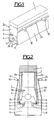
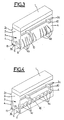
- FIGS. 1, 3 and 4 Internal combustion engines are well known to those skilled in the art (see for example European patent n ° 0 435 847 cited above) and will not be described in detail. Thereafter, we will only describe the structure of the engine directly concerned by the present invention.
- the internal combustion engine comprises a cylinder head 1 mounted above an elongated cylinder block 2.
- the cylinder block comprises several cylinders 2a in which pistons, not shown, slide.
- the cylinder block 2 has interior channels 2b in which a cylinder block coolant circulates.
- Below the cylinder block 2 are several crankshaft bearings 3 aligned along the cylinder block 2.
- Each bearing 3 is in the form of a vertical plate in two parts: a base 3a integral with the cylinder block 2 and a cap 3b mounted removably on the base 3a.
- a not shown crankshaft is supported by the crankshaft bearings 3 and driven by the not shown pistons of the engine in order to actuate a gearbox not shown of the vehicle.
- the lateral sides of the cylinder block 2 are extended downwards by two hanging skirts 4 in the form of a plate.
- the hanging skirts 4 are integral with the cylinder block 2 and deviate slightly to the side so as not to come into direct contact with the crankshaft bearings 3.
- the hanging skirts 4 may have internal pockets 4a into which is introduced a granular material 5 (pumice, sand, etc.), the usefulness of which will be described later.
- Two stiffening bars 6 parallel and longitudinal are mounted on the bearing caps 3b of the crankshaft 3 for example by means of bolts 7.
- the bearing caps 3b have a substantially inverted U shape whose ends of the branches are integral with the stiffening bars 6. Thus, two stiffening beams are obtained for the crankshaft bearings 3.
- the cylinder block 2 laterally has two longitudinal flanges 2c to allow the fixing of an oil pan 8 in the form of a large bowl of flexible material. Oil 9 in the oil pan 8 is intended for the lubrication of the engine, and is recycled by means of a suitable circuit not shown. At the side flanges 2c there are four lateral hooking elements 10 allowing the engine to be hooked into the chassis of the vehicle, not shown.
- the internal structure of the engine constituted by the cylinder head 1, the cylinder block 2, the crankshaft bearings 3, the hanging skirts 4 and the stiffening bars 6 is rigid.
- the external structure of the motor constituted by the large bowl 8 is flexible and mechanically decoupled from the rigid internal structure.
- the stiffening bars 6 make it possible to stiffen the crankshaft bearings 3 in a solid block to prevent their vibrations caused by the operation of the engine (movement of the pistons in the cylinders and movement of the crankshaft).
- the vibrations of the cylinder block 2 are mechanically propagated by the hanging skirts 4, the free lower end of which radiates.
- the granular material 5 contained in the internal pockets 4a of the skirts 4 makes it possible to dampen the vibrations by dry friction between the grains of the material.
- Damping elements 11 are provided between the caps 3b of crankshaft bearings 3 and the lower end of the hanging skirts 4, in order to dampen the vibrations radiated by said free ends.
- the damping elements 11 are dynamic dampers, for example viscous of a non-linear nature.
- the rigid internal structure of the engine ensures good reduction of vibrations, direct sources of noise emissions.
- the large bowl 8 is mechanically decoupled from the rigid internal structure so that the vibrations of the internal structure of the engine are not transferred to the external environment.
- the large bowl 8 is preferably made of flexible material, for example composite, and constitutes an acoustic screen which encloses the internal structure with their mechanical vibrations and sound emissions.
- One solution consists in replacing the skirts in the form of a plate with several hanging beams 4b (FIG. 3). These beams 4b have different dimensions to constitute dynamic absorbers frequency tuned vibrations. The damping of these beams 4b should take account of the characteristics of each beam in order to effectively cover the whole spectrum of vibrations to be treated. Solutions for including granular materials in the skirts 4 and / or dynamic dampers at the ends of the beams 4b can be used. Having tuned beams and dynamically damped, greatly reduced the acoustic radiation coefficient of the skirts 4 as a whole.
- FIG. 4 Another solution (FIG. 4) consists in providing lateral openings 4c in the hanging skirts 4. This also makes it possible to reduce the coefficient of acoustic radiation of the hanging skirts 4.
Landscapes
- Engineering & Computer Science (AREA)
- Chemical & Material Sciences (AREA)
- Combustion & Propulsion (AREA)
- Mechanical Engineering (AREA)
- General Engineering & Computer Science (AREA)
- Physics & Mathematics (AREA)
- Acoustics & Sound (AREA)
- Cylinder Crankcases Of Internal Combustion Engines (AREA)
- Vibration Prevention Devices (AREA)
Applications Claiming Priority (2)
| Application Number | Priority Date | Filing Date | Title |
|---|---|---|---|
| FR9312080 | 1993-10-11 | ||
| FR9312080A FR2711186B1 (fr) | 1993-10-11 | 1993-10-11 | Moteur à combustion interne à jupes amorties et à grande cuvette. |
Publications (2)
| Publication Number | Publication Date |
|---|---|
| EP0647772A1 true EP0647772A1 (de) | 1995-04-12 |
| EP0647772B1 EP0647772B1 (de) | 1997-06-11 |
Family
ID=9451715
Family Applications (1)
| Application Number | Title | Priority Date | Filing Date |
|---|---|---|---|
| EP19940402244 Expired - Lifetime EP0647772B1 (de) | 1993-10-11 | 1994-10-06 | Zylinderblock und Kurbelwellenlager für Brennkraftmaschine mit niedrigem Geräuschpegel |
Country Status (3)
| Country | Link |
|---|---|
| EP (1) | EP0647772B1 (de) |
| DE (1) | DE69403745T2 (de) |
| FR (1) | FR2711186B1 (de) |
Cited By (1)
| Publication number | Priority date | Publication date | Assignee | Title |
|---|---|---|---|---|
| EP3438435A4 (de) * | 2016-03-31 | 2019-03-20 | Yanmar Co., Ltd. | Motorvorrichtung |
Families Citing this family (2)
| Publication number | Priority date | Publication date | Assignee | Title |
|---|---|---|---|---|
| DE102005028775A1 (de) * | 2005-06-22 | 2007-01-04 | Daimlerchrysler Ag | Kurbelgehäuse für eine Brennkraftmaschine |
| WO2008078145A1 (en) * | 2006-12-27 | 2008-07-03 | Renault Trucks | Internal combustion engine with bearing cap dampening |
Citations (5)
| Publication number | Priority date | Publication date | Assignee | Title |
|---|---|---|---|---|
| DE2043280A1 (de) * | 1969-09-08 | 1971-04-15 | List, Hans, Dipl Ing Prof Dr Dr h c , Graz (Österreich) | Brennkraftmaschine mit schall dämmender Verschalung |
| GB1428754A (en) * | 1972-10-20 | 1976-03-17 | List H | Reciprocating machine with a sound-proofing casing |
| FR2449788A1 (fr) * | 1979-02-26 | 1980-09-19 | Steyr Daimler Puch Ag | Moteur a combustion interne a pistons alternatifs |
| US4257369A (en) * | 1977-09-06 | 1981-03-24 | Nissan Motor Company, Limited | Internal combustion engine equipped with noise control device |
| EP0038560A1 (de) * | 1980-04-21 | 1981-10-28 | Nissan Motor Co., Ltd. | Brennkraftmaschine |
-
1993
- 1993-10-11 FR FR9312080A patent/FR2711186B1/fr not_active Expired - Fee Related
-
1994
- 1994-10-06 EP EP19940402244 patent/EP0647772B1/de not_active Expired - Lifetime
- 1994-10-06 DE DE1994603745 patent/DE69403745T2/de not_active Expired - Fee Related
Patent Citations (5)
| Publication number | Priority date | Publication date | Assignee | Title |
|---|---|---|---|---|
| DE2043280A1 (de) * | 1969-09-08 | 1971-04-15 | List, Hans, Dipl Ing Prof Dr Dr h c , Graz (Österreich) | Brennkraftmaschine mit schall dämmender Verschalung |
| GB1428754A (en) * | 1972-10-20 | 1976-03-17 | List H | Reciprocating machine with a sound-proofing casing |
| US4257369A (en) * | 1977-09-06 | 1981-03-24 | Nissan Motor Company, Limited | Internal combustion engine equipped with noise control device |
| FR2449788A1 (fr) * | 1979-02-26 | 1980-09-19 | Steyr Daimler Puch Ag | Moteur a combustion interne a pistons alternatifs |
| EP0038560A1 (de) * | 1980-04-21 | 1981-10-28 | Nissan Motor Co., Ltd. | Brennkraftmaschine |
Cited By (2)
| Publication number | Priority date | Publication date | Assignee | Title |
|---|---|---|---|---|
| EP3438435A4 (de) * | 2016-03-31 | 2019-03-20 | Yanmar Co., Ltd. | Motorvorrichtung |
| US12221938B2 (en) | 2016-03-31 | 2025-02-11 | Yanmar Power Technology Co., Ltd. | Engine cylinder block structure |
Also Published As
| Publication number | Publication date |
|---|---|
| FR2711186A1 (fr) | 1995-04-21 |
| FR2711186B1 (fr) | 1995-12-08 |
| EP0647772B1 (de) | 1997-06-11 |
| DE69403745T2 (de) | 1997-10-23 |
| DE69403745D1 (de) | 1997-07-17 |
Similar Documents
| Publication | Publication Date | Title |
|---|---|---|
| EP1185801B1 (de) | Dämpfungsstruktur und anwendungen | |
| EP0983922A1 (de) | Drehgestell mit Komposit-Längsträgern | |
| EP0653344A1 (de) | Rahmen für Kraftfahrzeug | |
| FR2670552A1 (fr) | Attache hydroelastique de suspension et biellette de liaison geometrique liee a cette attache. | |
| EP0647772B1 (de) | Zylinderblock und Kurbelwellenlager für Brennkraftmaschine mit niedrigem Geräuschpegel | |
| FR2549533A1 (fr) | Moteur a combustion interne constituant un ensemble porteur avec un cadre | |
| JPS6220361B2 (de) | ||
| EP0841204B1 (de) | Kraftfahrzeugmotoren mit Wegbegrenzungs- Lagereinheit | |
| US20120247417A1 (en) | Internal combustion engine with bearing cap dampening | |
| FR3012653A1 (fr) | Revetement isolant acoustiquement muni de resonateurs, un panneau muni de ce revetement, et un aeronef | |
| EP1745223B1 (de) | Hoch-dämpfende absorbierende beschichtung | |
| EP0392909A1 (de) | Elastische, hydraulisch gedämpfte Buchse mit radialer Elastizität und Entkoppelung der Steifigkeiten | |
| FR2655113A1 (fr) | Dispositif d'amortissement en elastomere rempli d'un fluide. | |
| FR3128209A1 (fr) | Dispositif de manutention et de transfert d’un moteur d’aeronef, systeme et procédé d’arrimage associé | |
| FR3110115A1 (fr) | Renfort latéral de plancher de véhicule automobile équipé de batteries de traction | |
| EP1682371B1 (de) | Vorrichtung zur befestigung einer motor-getriebe-einheit an einem fahrzeugrahmen mittels einer zugstange | |
| FR2711210A1 (fr) | Carter antivibrations à treillis pour moteur à combustion interne. | |
| EP0691481A1 (de) | Verbesserungen an Pleuelstangen, die bestimmte Schwingelemente von Fahrzeugen an deren Wagenkasten befestigen | |
| FR2941191A1 (fr) | Ecran acoustique. | |
| WO1998047574A1 (fr) | Raquette de tennis equipee d'elements oscillants pour l'amortissement des vibrations | |
| EP0048659B1 (de) | Rumpfaufhängung für ein Landfahrzeug | |
| FR2570128A1 (fr) | Carter de vilebrequin a carter d'huile pour machines alternatives a plusieurs cylindres | |
| FR2742063A1 (fr) | Organe de glisse, tel que patin | |
| FR2784962A1 (fr) | Generateur solaire pour satellites | |
| FR2630175A1 (fr) | Dispositif amovible d'absorption de vibrations |
Legal Events
| Date | Code | Title | Description |
|---|---|---|---|
| PUAI | Public reference made under article 153(3) epc to a published international application that has entered the european phase |
Free format text: ORIGINAL CODE: 0009012 |
|
| AK | Designated contracting states |
Kind code of ref document: A1 Designated state(s): DE IT |
|
| 17P | Request for examination filed |
Effective date: 19950921 |
|
| GRAG | Despatch of communication of intention to grant |
Free format text: ORIGINAL CODE: EPIDOS AGRA |
|
| 17Q | First examination report despatched |
Effective date: 19960816 |
|
| GRAH | Despatch of communication of intention to grant a patent |
Free format text: ORIGINAL CODE: EPIDOS IGRA |
|
| GRAH | Despatch of communication of intention to grant a patent |
Free format text: ORIGINAL CODE: EPIDOS IGRA |
|
| GRAA | (expected) grant |
Free format text: ORIGINAL CODE: 0009210 |
|
| RAP1 | Party data changed (applicant data changed or rights of an application transferred) |
Owner name: RENAULT VEHICULES INDUSTRIELS |
|
| AK | Designated contracting states |
Kind code of ref document: B1 Designated state(s): DE IT |
|
| REF | Corresponds to: |
Ref document number: 69403745 Country of ref document: DE Date of ref document: 19970717 |
|
| PLBE | No opposition filed within time limit |
Free format text: ORIGINAL CODE: 0009261 |
|
| STAA | Information on the status of an ep patent application or granted ep patent |
Free format text: STATUS: NO OPPOSITION FILED WITHIN TIME LIMIT |
|
| 26N | No opposition filed | ||
| PGFP | Annual fee paid to national office [announced via postgrant information from national office to epo] |
Ref country code: DE Payment date: 20081014 Year of fee payment: 15 |
|
| PGFP | Annual fee paid to national office [announced via postgrant information from national office to epo] |
Ref country code: IT Payment date: 20081028 Year of fee payment: 15 |
|
| PG25 | Lapsed in a contracting state [announced via postgrant information from national office to epo] |
Ref country code: DE Free format text: LAPSE BECAUSE OF NON-PAYMENT OF DUE FEES Effective date: 20100501 |
|
| PG25 | Lapsed in a contracting state [announced via postgrant information from national office to epo] |
Ref country code: IT Free format text: LAPSE BECAUSE OF NON-PAYMENT OF DUE FEES Effective date: 20091006 |