EP0647784B1 - Diaphragm assembly for an accumulator tank - Google Patents
Diaphragm assembly for an accumulator tank Download PDFInfo
- Publication number
- EP0647784B1 EP0647784B1 EP94305544A EP94305544A EP0647784B1 EP 0647784 B1 EP0647784 B1 EP 0647784B1 EP 94305544 A EP94305544 A EP 94305544A EP 94305544 A EP94305544 A EP 94305544A EP 0647784 B1 EP0647784 B1 EP 0647784B1
- Authority
- EP
- European Patent Office
- Prior art keywords
- liners
- diaphragm
- pressure vessel
- filament
- end faces
- Prior art date
- Legal status (The legal status is an assumption and is not a legal conclusion. Google has not performed a legal analysis and makes no representation as to the accuracy of the status listed.)
- Expired - Lifetime
Links
- 239000004033 plastic Substances 0.000 claims abstract description 9
- XLYOFNOQVPJJNP-UHFFFAOYSA-N water Substances O XLYOFNOQVPJJNP-UHFFFAOYSA-N 0.000 claims description 12
- 238000000034 method Methods 0.000 claims description 6
- 238000009730 filament winding Methods 0.000 claims description 5
- 238000001746 injection moulding Methods 0.000 claims description 4
- 238000004804 winding Methods 0.000 claims description 4
- 238000001914 filtration Methods 0.000 claims 1
- 238000010438 heat treatment Methods 0.000 claims 1
- 230000004927 fusion Effects 0.000 abstract description 3
- 238000003466 welding Methods 0.000 abstract 1
- 239000007788 liquid Substances 0.000 description 3
- 230000008901 benefit Effects 0.000 description 2
- 238000004891 communication Methods 0.000 description 2
- 238000001125 extrusion Methods 0.000 description 2
- 239000012530 fluid Substances 0.000 description 2
- 230000013011 mating Effects 0.000 description 2
- 239000000155 melt Substances 0.000 description 2
- 229920001169 thermoplastic Polymers 0.000 description 2
- 239000004416 thermosoftening plastic Substances 0.000 description 2
- 235000020681 well water Nutrition 0.000 description 2
- 239000002349 well water Substances 0.000 description 2
- 230000008859 change Effects 0.000 description 1
- 238000001816 cooling Methods 0.000 description 1
- 230000009977 dual effect Effects 0.000 description 1
- 239000003365 glass fiber Substances 0.000 description 1
- 230000006872 improvement Effects 0.000 description 1
- 238000009434 installation Methods 0.000 description 1
- 230000007246 mechanism Effects 0.000 description 1
- 239000002184 metal Substances 0.000 description 1
- 238000012986 modification Methods 0.000 description 1
- 230000004048 modification Effects 0.000 description 1
- 238000000465 moulding Methods 0.000 description 1
- 238000004023 plastic welding Methods 0.000 description 1
- 238000009428 plumbing Methods 0.000 description 1
- 230000008707 rearrangement Effects 0.000 description 1
- 230000002787 reinforcement Effects 0.000 description 1
- 230000003014 reinforcing effect Effects 0.000 description 1
- 239000011347 resin Substances 0.000 description 1
- 229920005989 resin Polymers 0.000 description 1
- 230000000717 retained effect Effects 0.000 description 1
- 238000007789 sealing Methods 0.000 description 1
- 229920001187 thermosetting polymer Polymers 0.000 description 1
Images

Classifications
-
- F—MECHANICAL ENGINEERING; LIGHTING; HEATING; WEAPONS; BLASTING
- F16—ENGINEERING ELEMENTS AND UNITS; GENERAL MEASURES FOR PRODUCING AND MAINTAINING EFFECTIVE FUNCTIONING OF MACHINES OR INSTALLATIONS; THERMAL INSULATION IN GENERAL
- F16L—PIPES; JOINTS OR FITTINGS FOR PIPES; SUPPORTS FOR PIPES, CABLES OR PROTECTIVE TUBING; MEANS FOR THERMAL INSULATION IN GENERAL
- F16L55/00—Devices or appurtenances for use in, or in connection with, pipes or pipe systems
- F16L55/04—Devices damping pulsations or vibrations in fluids
- F16L55/045—Devices damping pulsations or vibrations in fluids specially adapted to prevent or minimise the effects of water hammer
- F16L55/05—Buffers therefor
- F16L55/052—Pneumatic reservoirs
- F16L55/053—Pneumatic reservoirs the gas in the reservoir being separated from the fluid in the pipe
Definitions
- This invention relates to a filament-wound hydropneumatic accumulator tank containing a flexible diaphragm which separates the interior of the tank into a compressible gas-containing chamber and a liquid-containing chamber.
- Accumulator or pressure-controlled devices are especially adapted for liquid dispensing systems and, particularly, for water systems dependant upon well water, a pump and, because of intermittent use, an intermittent source of pressurization for the system.
- a simple prior art system for accumulating the pressurization of a well water system for example, in a dwelling, comprises a pipe extending into the underground water supply, a pump, and a reservoir tank. Frequently, the tank is a metal container having no valve and in which air is merely trapped.
- a valve such as a conventional tire valve, may be positioned at or near the top of the container, and an outlet may be provided near the bottom.
- a diaphragm is not provided, but it is highly desirable to separate the air from the water and the tank since air will dissolve in the water and may create a "white water" problem at the taps.
- a charge of air is introduced in the tank, usually occupying about one-half of the volume of the tank and to a pressure sufficient to force water into the plumbing system connected thereto.
- a pressure switch senses the pressure within the tank or in the water line, as the case may be, and operates between limits, for example, between twenty and forty PSI. If the pressure falls below twenty PSI, the pump is activated and continues to operate until the pressure in the system is built up to forty PSI, causing the pump to be turned off by the pressure switch.
- Typical prior art accumulators include a pressure vessel having an expansible bag therein which may be either an inflatable bag which stretches upon the introduction of air, or which merely unfolds as the air volume increases, or the expansible bag may unfold and also expand.
- An air valve extends through one end of the tank, and an inlet and outlet aperture is provided at the other end of the tank for fluid communication with the water system. As water is pumped into the tank, the bag is forced upwardly by the incoming water.
- Separator bags or diaphragms in pressure tanks are either diaphragm-type separators peripherally sealed, or otherwise attached to the sidewall of the tank, usually at an assembly seam wherein the tank is formed by a pair of cup-shaped halves or comprises a removable cell which may be removed and replaced upon failure. Both arrangements have advantages and disadvantages.
- the primary advantage of a diaphragm-type separator is that the diaphragm may be constructed from a relatively heavy gauge, plastic, or rubber, and may be shaped to conform to the cross-section of the tank to eliminate stretching. This arrangement, however, involves the dual problem of providing a pressure-tight seal between the mating halves of the pressure vessel and between the sidewall of the vessel and the diaphragm.
- a filament-wound, non-metallic pressure vessel includes an assembly ring which provides a pressure-tight joint between the diaphragm and the sidewall of one of the liners and provides a seal with respect to the other liner.
- the assembly comprises cup-shaped liners, and the assembly ring provides a smooth exterior surface which may be filament-wound, employing conventional winding techniques.
- the liners form a dovetail joint with the ring and respectively trap an O-ring and a bulbous portion of the diaphragm between recessed portions of the liner and a surface of the ring to seal the interior of the tank.
- the dovetail connection between the cup-shaped liners and the ring is a dynamic seal in the sense that these elements are not physically joined by any mechanism other than the filament winding which retain the elements in an assembled condition.
- the seals which include the aforementioned O-ring and the bulbous portion of the diaphragm, are relied upon to prevent leakage of the pressure vessel.
- an O-ring performs its sealing function depends, to a large degree, on its position between the elements to be sealed.
- the O-ring performs its intended function.
- pressurization of the pressure vessel causes the liner walls to flex and change the dimensions of the seat for the O-ring, thus creating a potential leakage situation and/or extrusion of the O-ring into the sealed joint.
- the bulbous seal portion of the diaphragm merely approximates the configuration of an O-ring and may not form an adequate seal.
- a hydropneumatic filament-wound pressure vessel having a split tank closure and diaphragm assembly
- first and second cup-shaped plastic tank liners said liners having oblate ellipsoidal end portions and cylindrical sidewall portions terminating in circular open mouth portions having opposed first and second annular end faces, a cylindrical ring having third and fourth annular end faces and a resin-impregnated filament winding covering the liners and the outside surface of said ring means in a predetermined winding pattern, characterised in that the third and fourth annular end faces are fused respectively to said first and second end faces to seal said liners into a unitary pressure vessel liner, said cylindrical ring having inside and outside surfaces having diameters corresponding to inside and outside diameters of said cylindrical sidewall portions of said liners, a stiffly flexible elastomeric cup-shaped diaphragm having an oblate ellipsoidal end portion and a cylindrical sidewall portion terminating in an open mouth
- a method of forming a hydropneumatic filament-wound pressure vessel characterised in that the diaphragm is fused to the inside surface of the cylindrical ring within the mold cavity of an injection molding machine.
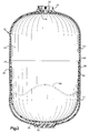
- an accumulator vessel or tank 10 which is formed by cup-shaped thermoplastic tank shelves or liners 12 and 14.
- the liners 12 and 14 are, preferably, injection-molded, but may be formed by other molding techniques. Moreover, the liners 12 and 14 may be formed by techniques involving the use of fibrous reinforcing forms and thermosetting resin systems.
- the liner 12 may be provided with a circular recess 16 which receives a cup-shaped plastic valve guard 18 which may be cemented within the recess 16.
- a conventional one-way check valve such as a conventional tire valve 20, is provided within the guard 18 and extends through the guard 18 and the liner 12 for fluid communication with a pressure chamber 22 within the tank 10.
- the cup-shaped liner 14 is molded about a tank end fitting 28 which is provided with a threaded access opening 30.
- the fitting 28 may be provided as an insert during the injection molding operation and fused to the cup-shaped liner 14 during that operation.
- the liners 12 and 14 terminate in circular open mouth portions which have opposed annular end faces 34 and 36, respectively, and the liners 12 and 14 are retained in mouth-to-mouth apposition to form a sealed container by a cylindrical mounting ring 38.
- the cylindrical ring 38 has end faces 40 and 42 which are respectively fused to the faces 34 and 36 by fusion welds 44 and 46.
- the fusion welds 44 and 46 are accomplished by feeding a supply of plastic in rod form to the tip of a plastic extrusion welder gun.
- the tip of the gun incorporates a controlled heater that partially melts the joint to be welded.
- the plastic immediately adjacent the faces 34, 40, 42 and 36 partially melts together with the plastic welding rod to form a fused joint upon cooling of the assembly.
- the mounting ring 38 is defined by a cylindrical outer surface which corresponds to the outside diameter of the cylindrical sidewall portions of the liners 12 and 14.
- the ring 38 has an inside surface 50 which corresponds to the inside diameter of the cylindrical sidewall portions of
- a stiffly flexible elastomeric thermoplastic injection-molded diaphragm 66 separates the pressure chamber 22 to form water and air cells within the tank 10.
- the diaphragm 66 is fused to the ring 38.
- the ring 38 may be mounted as an insert within the mold cavity of an injection-molding machine so that the hot, liquid plastic forming the diaphragm in the mold will contact and fuse with the ring 38.
Landscapes
- Engineering & Computer Science (AREA)
- General Engineering & Computer Science (AREA)
- Mechanical Engineering (AREA)
- Supply Devices, Intensifiers, Converters, And Telemotors (AREA)
- Filling Or Discharging Of Gas Storage Vessels (AREA)
- Separation Using Semi-Permeable Membranes (AREA)
- Materials For Medical Uses (AREA)
Applications Claiming Priority (2)
| Application Number | Priority Date | Filing Date | Title |
|---|---|---|---|
| US08/132,845 US5368073A (en) | 1993-10-07 | 1993-10-07 | Hydropneumatic pressure vessel having an improved diaphragm assembly |
| US132845 | 1993-10-07 |
Publications (2)
| Publication Number | Publication Date |
|---|---|
| EP0647784A1 EP0647784A1 (en) | 1995-04-12 |
| EP0647784B1 true EP0647784B1 (en) | 1998-05-27 |
Family
ID=22455861
Family Applications (1)
| Application Number | Title | Priority Date | Filing Date |
|---|---|---|---|
| EP94305544A Expired - Lifetime EP0647784B1 (en) | 1993-10-07 | 1994-07-27 | Diaphragm assembly for an accumulator tank |
Country Status (6)
| Country | Link |
|---|---|
| US (1) | US5368073A (da) |
| EP (1) | EP0647784B1 (da) |
| AT (1) | ATE166704T1 (da) |
| DE (1) | DE69410564T2 (da) |
| DK (1) | DK0647784T3 (da) |
| GR (1) | GR3027745T3 (da) |
Families Citing this family (32)
| Publication number | Priority date | Publication date | Assignee | Title |
|---|---|---|---|---|
| US5709248A (en) * | 1996-09-30 | 1998-01-20 | Caterpillar Inc. | Internal accumulator for hydraulic systems |
| US5682923A (en) * | 1996-09-30 | 1997-11-04 | Caterpillar Inc. | Accumulator having an internal elastomeric member |
| IT238360Y1 (it) * | 1997-10-13 | 2000-10-16 | Marinox Pompe Di Angoli Marghe | Pompa con serbatoio d'accumulo |
| DE19813970A1 (de) * | 1998-03-20 | 1999-09-30 | Otto Heat Heizungs | Kombiniertes Brauch- und Heizungswasserausdehnungsgefäß |
| US6430928B1 (en) * | 2000-07-20 | 2002-08-13 | Automotive Products (Usa), Inc. | Dual action damper for hydraulic clutch actuator |
| US6554939B1 (en) | 2000-10-10 | 2003-04-29 | Pentair Pool Products, Inc. | Container and method of forming the container |
| DE10051580A1 (de) * | 2000-10-18 | 2002-05-08 | Hydac Technology Gmbh | Hydrospeicher, insbesondere Blasenspeicher |
| WO2003031860A1 (en) * | 2001-10-12 | 2003-04-17 | Polymer & Steel Technologies Holding Company, L.L.C. | Composite pressure vessel assembly and method |
| BE1014807A5 (nl) * | 2002-04-30 | 2004-04-06 | Groep Stevens International Na | Fluidumaccumulator en werkwijze voor het vervaardigen ervan. |
| DE10307587A1 (de) * | 2003-02-22 | 2004-09-09 | Hydac Technology Gmbh | Speichervorrichtung, vorzugsweise Membranspeicher |
| AU2003217924A1 (en) * | 2003-03-05 | 2004-09-28 | Polymer And Steel Technologies Holding Company, L.L.C. | Vessel diaphragm and method |
| US20040173624A1 (en) * | 2003-03-05 | 2004-09-09 | Polymer & Steel Technologies Holding Company, L.L.C. | Vessel diaphragm and method |
| CN100430655C (zh) * | 2003-07-22 | 2008-11-05 | 弗莱克斯康工业公司 | 具有双隔膜的膨胀水箱 |
| US20050040253A1 (en) * | 2003-08-21 | 2005-02-24 | Thornton David L. | Pressurized accumulator tank for flowable materials |
| JP2007537109A (ja) * | 2004-05-12 | 2007-12-20 | アムトロール,インコーポレーテッド | 内部ダイアフラムを有する非金属膨張タンクおよびダイアフラム用締め付け装置 |
| US7753252B2 (en) * | 2005-05-05 | 2010-07-13 | Smith International | Method for construction of pressure vessels with a liner using friction stirring processes |
| US20070186873A1 (en) * | 2006-02-13 | 2007-08-16 | Nikolay Polkhouskiy | Pressure control isolation and flood preventative tank for a hot water based heating system |
| US9278478B2 (en) * | 2007-04-05 | 2016-03-08 | Curtis Goad | Methods and apparatus for lining process tanks |
| US10138053B2 (en) | 2007-04-05 | 2018-11-27 | Curtis Goad | Methods and apparatus for lining process tanks |
| US9090398B2 (en) | 2007-05-04 | 2015-07-28 | Emd Millipore Corporation | Disposable processing bag with alignment feature |
| DE102010026092A1 (de) * | 2010-07-05 | 2012-01-05 | Robert Bosch Gmbh | Druckspeichervorrichtung zur Verbindung mit einer hydraulischen Anlage |
| US10392186B2 (en) | 2012-03-22 | 2019-08-27 | Curtis Goad | Liners and linings for tanks and other liquid containment vessels |
| US8403170B1 (en) * | 2012-04-20 | 2013-03-26 | Ming-Yu Lai | Pressure vessel |
| US9127811B2 (en) | 2013-06-05 | 2015-09-08 | Louis P. Vickio, Jr. | Hydraulic accumulator |
| EP3049350A1 (en) | 2013-09-24 | 2016-08-03 | Pentair Residential Filtration, LLC | Pressure vessel system and method |
| US20190085536A1 (en) * | 2016-03-31 | 2019-03-21 | Flexcon Industries, Inc. | Expansion tank with improved single diaphragm |
| US20190113054A1 (en) * | 2016-03-31 | 2019-04-18 | Flexcon Industries, Inc. | Expansion tank with decoupled single flexible diaphragm |
| US10724684B2 (en) | 2016-09-20 | 2020-07-28 | Amtrol Licensing Inc. | Fiberwound tanks |
| US10641431B2 (en) * | 2016-12-22 | 2020-05-05 | Steelhead Composites, Llc | Lightweight composite overwrapped pressure vessels with sectioned liners |
| US11448364B2 (en) | 2016-12-22 | 2022-09-20 | Steelhead Composites, Inc. | Lightweight composite overwrapped accumulators |
| US11376783B2 (en) | 2018-10-31 | 2022-07-05 | Curtis Goad | Corner profiles and/or corner reinforcement for liners and linings suitable for use with tanks and other storage/containment vessels |
| US11396125B2 (en) | 2019-04-19 | 2022-07-26 | Goad Company | Liners and methods of making liners |
Family Cites Families (7)
| Publication number | Priority date | Publication date | Assignee | Title |
|---|---|---|---|---|
| DE2336965A1 (de) * | 1973-07-20 | 1975-02-06 | Hydraulik Zubehoer Ges Fuer | Hydropneumatischer druckspeicher |
| AU7940875A (en) * | 1975-04-01 | 1976-09-30 | Fawcett Eng Ltd | Accumulator |
| US4595037A (en) * | 1984-12-14 | 1986-06-17 | Essef Industries, Inc. | Split tank closure and diaphragm assembly |
| FR2575141B1 (fr) * | 1984-12-21 | 1987-03-20 | Gitral Sa | Reservoir du type a deux demi-coquilles assemblees, applicable comme vase d'expansion, compensateur de dilatation, avec de reserve de fluides sous pression |
| IT1185613B (it) * | 1985-05-30 | 1987-11-12 | Magnaghi Cleodinamica Spa | Accumulatore di pressione gas-olio con struttura in materiali compositi per circuiti idraulici di velivoli |
| DE3628608A1 (de) * | 1986-08-22 | 1988-03-03 | Bosch Gmbh Robert | Elastische trennwand |
| FR2640018A1 (fr) * | 1988-11-08 | 1990-06-08 | Olaer Ind Sa | Separateur souple composite pour reservoir de pression, son procede de realisation, et reservoir de pression comportant un tel separateur souple |
-
1993
- 1993-10-07 US US08/132,845 patent/US5368073A/en not_active Expired - Lifetime
-
1994
- 1994-07-27 EP EP94305544A patent/EP0647784B1/en not_active Expired - Lifetime
- 1994-07-27 DK DK94305544T patent/DK0647784T3/da active
- 1994-07-27 AT AT94305544T patent/ATE166704T1/de not_active IP Right Cessation
- 1994-07-27 DE DE69410564T patent/DE69410564T2/de not_active Expired - Fee Related
-
1998
- 1998-08-27 GR GR980401924T patent/GR3027745T3/el unknown
Also Published As
| Publication number | Publication date |
|---|---|
| DK0647784T3 (da) | 1999-03-22 |
| DE69410564T2 (de) | 1999-02-04 |
| US5368073A (en) | 1994-11-29 |
| EP0647784A1 (en) | 1995-04-12 |
| GR3027745T3 (en) | 1998-11-30 |
| DE69410564D1 (de) | 1998-07-02 |
| ATE166704T1 (de) | 1998-06-15 |
Similar Documents
| Publication | Publication Date | Title |
|---|---|---|
| EP0647784B1 (en) | Diaphragm assembly for an accumulator tank | |
| US4595037A (en) | Split tank closure and diaphragm assembly | |
| US20080017653A1 (en) | Vessel diaphragm and method | |
| US4836409A (en) | Integral diaphragm-liner bladder for hydropneumatic tank | |
| US4637435A (en) | Antiseal arrangement for hydropneumatic pressure tanks | |
| EP1266698B1 (en) | Separable laminated container | |
| US9751689B2 (en) | Pressure vessel system and method | |
| KR101745031B1 (ko) | 압력 용기의 용기 넥 구성 | |
| US7322488B2 (en) | Expansion tank with double diaphragm | |
| US5806705A (en) | Sealing technique for hydropneumatic pressure vessel | |
| EP0744274B1 (en) | Hydropneumatic filament wound pressure vessel | |
| US4214611A (en) | Tie-down for accumulator bags | |
| US5388720A (en) | Flanged diffuser and air cell retainer for pressure vessel | |
| US5484079A (en) | Hydropneumatic filament-wound pressure vessel | |
| EP1601902A2 (en) | Vessel diaphragm and method | |
| CA2584183C (en) | Expansion tank with double diaphragm | |
| US12313090B2 (en) | Hydro-pneumatic pressure vessel and diaphragm assembly method | |
| RU2582947C2 (ru) | Клапан регулирования давления для разливных аппаратов для напитков с вытеснением давлением | |
| CN115076078A (zh) | 膨胀容器及其制造方法和包括该膨胀容器的泵 | |
| JP2006007747A (ja) | タイヤのシーリング・ポンプアップ装置 | |
| CN223242531U (zh) | 压力储气罐 | |
| JPH10159803A (ja) | アキュムレータ | |
| CN112483761A (zh) | 具有膜的膨胀容器以及包括这种膨胀容器的泵 |
Legal Events
| Date | Code | Title | Description |
|---|---|---|---|
| PUAI | Public reference made under article 153(3) epc to a published international application that has entered the european phase |
Free format text: ORIGINAL CODE: 0009012 |
|
| AK | Designated contracting states |
Kind code of ref document: A1 Designated state(s): AT BE CH DE DK ES FR GB GR IE IT LI LU MC NL PT SE |
|
| 17P | Request for examination filed |
Effective date: 19950907 |
|
| 17Q | First examination report despatched |
Effective date: 19970404 |
|
| GRAG | Despatch of communication of intention to grant |
Free format text: ORIGINAL CODE: EPIDOS AGRA |
|
| GRAG | Despatch of communication of intention to grant |
Free format text: ORIGINAL CODE: EPIDOS AGRA |
|
| GRAH | Despatch of communication of intention to grant a patent |
Free format text: ORIGINAL CODE: EPIDOS IGRA |
|
| GRAH | Despatch of communication of intention to grant a patent |
Free format text: ORIGINAL CODE: EPIDOS IGRA |
|
| GRAA | (expected) grant |
Free format text: ORIGINAL CODE: 0009210 |
|
| AK | Designated contracting states |
Kind code of ref document: B1 Designated state(s): AT BE CH DE DK ES FR GB GR IE IT LI LU MC NL PT SE |
|
| PG25 | Lapsed in a contracting state [announced via postgrant information from national office to epo] |
Ref country code: BE Free format text: LAPSE BECAUSE OF FAILURE TO SUBMIT A TRANSLATION OF THE DESCRIPTION OR TO PAY THE FEE WITHIN THE PRESCRIBED TIME-LIMIT Effective date: 19980527 |
|
| REF | Corresponds to: |
Ref document number: 166704 Country of ref document: AT Date of ref document: 19980615 Kind code of ref document: T |
|
| REG | Reference to a national code |
Ref country code: CH Ref legal event code: EP |
|
| REF | Corresponds to: |
Ref document number: 69410564 Country of ref document: DE Date of ref document: 19980702 |
|
| PG25 | Lapsed in a contracting state [announced via postgrant information from national office to epo] |
Ref country code: ES Free format text: LAPSE BECAUSE OF NON-PAYMENT OF DUE FEES Effective date: 19980728 |
|
| ITF | It: translation for a ep patent filed | ||
| REG | Reference to a national code |
Ref country code: IE Ref legal event code: FG4D |
|
| REG | Reference to a national code |
Ref country code: CH Ref legal event code: AEN Free format text: DAS PATENT IST AUFGRUND DES WEITERBEHANDLUNGSANTRAGS VOM 17.09.1998 REAKTIVIERT WORDEN. |
|
| PGFP | Annual fee paid to national office [announced via postgrant information from national office to epo] |
Ref country code: BE Payment date: 19981022 Year of fee payment: 5 |
|
| ET | Fr: translation filed | ||
| REG | Reference to a national code |
Ref country code: PT Ref legal event code: SC4A Free format text: AVAILABILITY OF NATIONAL TRANSLATION Effective date: 19980821 Ref country code: CH Ref legal event code: NV Representative=s name: A. BRAUN, BRAUN, HERITIER, ESCHMANN AG PATENTANWAE |
|
| REG | Reference to a national code |
Ref country code: DK Ref legal event code: T3 |
|
| PLBE | No opposition filed within time limit |
Free format text: ORIGINAL CODE: 0009261 |
|
| STAA | Information on the status of an ep patent application or granted ep patent |
Free format text: STATUS: NO OPPOSITION FILED WITHIN TIME LIMIT |
|
| 26N | No opposition filed | ||
| REG | Reference to a national code |
Ref country code: GB Ref legal event code: IF02 |
|
| PGFP | Annual fee paid to national office [announced via postgrant information from national office to epo] |
Ref country code: AT Payment date: 20040608 Year of fee payment: 11 |
|
| PGFP | Annual fee paid to national office [announced via postgrant information from national office to epo] |
Ref country code: FR Payment date: 20040610 Year of fee payment: 11 |
|
| PGFP | Annual fee paid to national office [announced via postgrant information from national office to epo] |
Ref country code: DK Payment date: 20040611 Year of fee payment: 11 Ref country code: CH Payment date: 20040611 Year of fee payment: 11 |
|
| PGFP | Annual fee paid to national office [announced via postgrant information from national office to epo] |
Ref country code: NL Payment date: 20040614 Year of fee payment: 11 Ref country code: GB Payment date: 20040614 Year of fee payment: 11 |
|
| PGFP | Annual fee paid to national office [announced via postgrant information from national office to epo] |
Ref country code: SE Payment date: 20040616 Year of fee payment: 11 Ref country code: LU Payment date: 20040616 Year of fee payment: 11 |
|
| PGFP | Annual fee paid to national office [announced via postgrant information from national office to epo] |
Ref country code: PT Payment date: 20040618 Year of fee payment: 11 |
|
| PGFP | Annual fee paid to national office [announced via postgrant information from national office to epo] |
Ref country code: MC Payment date: 20040621 Year of fee payment: 11 Ref country code: DE Payment date: 20040621 Year of fee payment: 11 |
|
| PGFP | Annual fee paid to national office [announced via postgrant information from national office to epo] |
Ref country code: IE Payment date: 20040622 Year of fee payment: 11 |
|
| PGFP | Annual fee paid to national office [announced via postgrant information from national office to epo] |
Ref country code: GR Payment date: 20040625 Year of fee payment: 11 |
|
| PG25 | Lapsed in a contracting state [announced via postgrant information from national office to epo] |
Ref country code: LU Free format text: LAPSE BECAUSE OF NON-PAYMENT OF DUE FEES Effective date: 20050727 Ref country code: IT Free format text: LAPSE BECAUSE OF NON-PAYMENT OF DUE FEES;WARNING: LAPSES OF ITALIAN PATENTS WITH EFFECTIVE DATE BEFORE 2007 MAY HAVE OCCURRED AT ANY TIME BEFORE 2007. THE CORRECT EFFECTIVE DATE MAY BE DIFFERENT FROM THE ONE RECORDED. Effective date: 20050727 Ref country code: IE Free format text: LAPSE BECAUSE OF NON-PAYMENT OF DUE FEES Effective date: 20050727 Ref country code: GB Free format text: LAPSE BECAUSE OF NON-PAYMENT OF DUE FEES Effective date: 20050727 Ref country code: AT Free format text: LAPSE BECAUSE OF NON-PAYMENT OF DUE FEES Effective date: 20050727 |
|
| PG25 | Lapsed in a contracting state [announced via postgrant information from national office to epo] |
Ref country code: SE Free format text: LAPSE BECAUSE OF NON-PAYMENT OF DUE FEES Effective date: 20050728 |
|
| PG25 | Lapsed in a contracting state [announced via postgrant information from national office to epo] |
Ref country code: MC Free format text: LAPSE BECAUSE OF NON-PAYMENT OF DUE FEES Effective date: 20050731 Ref country code: LI Free format text: LAPSE BECAUSE OF NON-PAYMENT OF DUE FEES Effective date: 20050731 Ref country code: CH Free format text: LAPSE BECAUSE OF NON-PAYMENT OF DUE FEES Effective date: 20050731 |
|
| PG25 | Lapsed in a contracting state [announced via postgrant information from national office to epo] |
Ref country code: DK Free format text: LAPSE BECAUSE OF NON-PAYMENT OF DUE FEES Effective date: 20050801 |
|
| PG25 | Lapsed in a contracting state [announced via postgrant information from national office to epo] |
Ref country code: PT Free format text: LAPSE BECAUSE OF NON-PAYMENT OF DUE FEES Effective date: 20060127 |
|
| PG25 | Lapsed in a contracting state [announced via postgrant information from national office to epo] |
Ref country code: NL Free format text: LAPSE BECAUSE OF NON-PAYMENT OF DUE FEES Effective date: 20060201 Ref country code: DE Free format text: LAPSE BECAUSE OF NON-PAYMENT OF DUE FEES Effective date: 20060201 |
|
| PG25 | Lapsed in a contracting state [announced via postgrant information from national office to epo] |
Ref country code: GR Free format text: LAPSE BECAUSE OF NON-PAYMENT OF DUE FEES Effective date: 20060202 |
|
| REG | Reference to a national code |
Ref country code: CH Ref legal event code: PL |
|
| EUG | Se: european patent has lapsed | ||
| GBPC | Gb: european patent ceased through non-payment of renewal fee |
Effective date: 20050727 |
|
| PG25 | Lapsed in a contracting state [announced via postgrant information from national office to epo] |
Ref country code: FR Free format text: LAPSE BECAUSE OF NON-PAYMENT OF DUE FEES Effective date: 20060331 |
|
| NLV4 | Nl: lapsed or anulled due to non-payment of the annual fee |
Effective date: 20060201 |
|
| REG | Reference to a national code |
Ref country code: DK Ref legal event code: EBP |
|
| REG | Reference to a national code |
Ref country code: IE Ref legal event code: MM4A |
|
| REG | Reference to a national code |
Ref country code: FR Ref legal event code: ST Effective date: 20060331 |