EP0647857B1 - Hochgenauer Radar-Entfernungsmesser - Google Patents
Hochgenauer Radar-Entfernungsmesser Download PDFInfo
- Publication number
- EP0647857B1 EP0647857B1 EP94115413A EP94115413A EP0647857B1 EP 0647857 B1 EP0647857 B1 EP 0647857B1 EP 94115413 A EP94115413 A EP 94115413A EP 94115413 A EP94115413 A EP 94115413A EP 0647857 B1 EP0647857 B1 EP 0647857B1
- Authority
- EP
- European Patent Office
- Prior art keywords
- frequency
- range
- radar
- oscillator
- meter according
- Prior art date
- Legal status (The legal status is an assumption and is not a legal conclusion. Google has not performed a legal analysis and makes no representation as to the accuracy of the status listed.)
- Expired - Lifetime
Links
- 238000005259 measurement Methods 0.000 title abstract description 16
- 238000001228 spectrum Methods 0.000 claims description 8
- 230000005540 biological transmission Effects 0.000 claims description 6
- 238000005516 engineering process Methods 0.000 claims description 3
- 238000001914 filtration Methods 0.000 claims 1
- 238000000034 method Methods 0.000 description 9
- 238000010586 diagram Methods 0.000 description 5
- 230000003679 aging effect Effects 0.000 description 1
- 230000035559 beat frequency Effects 0.000 description 1
- 238000006243 chemical reaction Methods 0.000 description 1
- 238000001514 detection method Methods 0.000 description 1
- 238000011161 development Methods 0.000 description 1
- 230000018109 developmental process Effects 0.000 description 1
- 230000000694 effects Effects 0.000 description 1
- 238000004880 explosion Methods 0.000 description 1
- 239000007788 liquid Substances 0.000 description 1
- 230000007774 longterm Effects 0.000 description 1
- 238000005457 optimization Methods 0.000 description 1
- 230000003595 spectral effect Effects 0.000 description 1
- 238000010183 spectrum analysis Methods 0.000 description 1
- 230000001502 supplementing effect Effects 0.000 description 1
- 230000036962 time dependent Effects 0.000 description 1
- 230000009466 transformation Effects 0.000 description 1
- 238000002604 ultrasonography Methods 0.000 description 1
Images




Classifications
-
- G—PHYSICS
- G01—MEASURING; TESTING
- G01S—RADIO DIRECTION-FINDING; RADIO NAVIGATION; DETERMINING DISTANCE OR VELOCITY BY USE OF RADIO WAVES; LOCATING OR PRESENCE-DETECTING BY USE OF THE REFLECTION OR RERADIATION OF RADIO WAVES; ANALOGOUS ARRANGEMENTS USING OTHER WAVES
- G01S13/00—Systems using the reflection or reradiation of radio waves, e.g. radar systems; Analogous systems using reflection or reradiation of waves whose nature or wavelength is irrelevant or unspecified
- G01S13/02—Systems using reflection of radio waves, e.g. primary radar systems; Analogous systems
- G01S13/06—Systems determining position data of a target
- G01S13/08—Systems for measuring distance only
- G01S13/32—Systems for measuring distance only using transmission of continuous waves, whether amplitude-, frequency-, or phase-modulated, or unmodulated
- G01S13/34—Systems for measuring distance only using transmission of continuous waves, whether amplitude-, frequency-, or phase-modulated, or unmodulated using transmission of continuous, frequency-modulated waves while heterodyning the received signal, or a signal derived therefrom, with a locally-generated signal related to the contemporaneously transmitted signal
- G01S13/343—Systems for measuring distance only using transmission of continuous waves, whether amplitude-, frequency-, or phase-modulated, or unmodulated using transmission of continuous, frequency-modulated waves while heterodyning the received signal, or a signal derived therefrom, with a locally-generated signal related to the contemporaneously transmitted signal using sawtooth modulation
-
- G—PHYSICS
- G01—MEASURING; TESTING
- G01S—RADIO DIRECTION-FINDING; RADIO NAVIGATION; DETERMINING DISTANCE OR VELOCITY BY USE OF RADIO WAVES; LOCATING OR PRESENCE-DETECTING BY USE OF THE REFLECTION OR RERADIATION OF RADIO WAVES; ANALOGOUS ARRANGEMENTS USING OTHER WAVES
- G01S13/00—Systems using the reflection or reradiation of radio waves, e.g. radar systems; Analogous systems using reflection or reradiation of waves whose nature or wavelength is irrelevant or unspecified
- G01S13/02—Systems using reflection of radio waves, e.g. primary radar systems; Analogous systems
- G01S13/06—Systems determining position data of a target
- G01S13/08—Systems for measuring distance only
- G01S13/32—Systems for measuring distance only using transmission of continuous waves, whether amplitude-, frequency-, or phase-modulated, or unmodulated
- G01S13/34—Systems for measuring distance only using transmission of continuous waves, whether amplitude-, frequency-, or phase-modulated, or unmodulated using transmission of continuous, frequency-modulated waves while heterodyning the received signal, or a signal derived therefrom, with a locally-generated signal related to the contemporaneously transmitted signal
- G01S13/341—Systems for measuring distance only using transmission of continuous waves, whether amplitude-, frequency-, or phase-modulated, or unmodulated using transmission of continuous, frequency-modulated waves while heterodyning the received signal, or a signal derived therefrom, with a locally-generated signal related to the contemporaneously transmitted signal wherein the rate of change of the transmitted frequency is adjusted to give a beat of predetermined constant frequency, e.g. by adjusting the amplitude or frequency of the frequency-modulating signal
Definitions
- the invention relates to a highly accurate radar range finder, whose structure corresponds to the FMCW principle, according to the generic term of claim 1.
- An FMCW radar range finder is known from document US-A-5 191 337.
- Level measuring devices are in the most varied Embodiments known.
- the non-contact process Level measurement is based on radar methods, preferably on the Runtime measurement in the ultrasonic range or in the laser range.
- the ultra Sound sensors have the disadvantage that the speed of propagation of the sound changes with the level medium and thereby very considerable measurement errors arise.
- the laser sensors are included suffers from the disadvantage that, apart from the high purchase price, the Level with clear liquids is usually not recognizable, because the laser beam is not at the fill level but at the bottom of the container reflected.
- the radar sensors do not have these disadvantages.
- the requirements for a radar sensor are, apart from the one required high reliability, measuring the level with an accuracy in the cm range, compliance with prescribed frequency bands, due to the FTZ approval by the post office and the continued fulfillment of the Protection requirements of the Physikalisch-Technische Bundesweg, group 3.5 "Explosion protection of electrical equipment”.
- the transmission signal is modulated in either the time or frequency range.
- the modulation method is outlined in FIG. 2.
- Received signal carried out by means of discrete Fourier transformation. The relationships are shown in FIG. 3.
- the present invention has for its object a highly accurate Show radar level meter, which works according to the FMCW principle with digital Signal processing for highly accurate distance measurement with limited Frequency sweep works.
- the discrete Fourier transform of a time signal quasi decomposes the Detected area in so-called distance gates - or range gate called - as illustrated in Fig. 4, where each corresponds Distance gate of a spectral line, as in Flg. 3 shown.
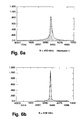
- the image sequence 6a to d shows how step-by-step optimization works of the stroke reduce the secondary lines in the spectrum.
- the signal energy is concentrated so on the main line, so that in the case of the optimized Hubes is "maximum".
- the distance accuracy is no longer alone determined by the maximum possible stroke, but rather by the accuracy, with which the optimal stroke is determined. This is first Line from the selected step size - i.e. from the maximum permissible Measuring time - dependent.
- the voltage controlled oscillator generates 1 (VCO) the fundamental frequency of 4,825 GHz.
- VCO the fundamental frequency of 4,825 GHz.
- this oscillator signal is amplified and at the same time the Oscillator 1 decoupled from further stages to create the so-called pulling effect to avoid which leads to a deviation from the linearity of the Frequency swing and thus to an inaccuracy in the distance determination would lead.
- the buffer amplifier 2 works in saturation mode and thus generates frequency components at the multiple of the fundamental frequency. It is designed that the fifth harmonic (24.125 GHz) is particularly prominent.
- the directional coupler 3 (20 dB) is dimensioned for the fundamental wave and couples it VCO signal to divider chain 4, 4a with a suitable level.
- This divider chain 4, 4a which consists of several divider stages, sets the oscillator frequency in the MHz range. For the required linearization this frequency is now the control loop via a counter 5, one Microprocessor 6 and a D / A converter 7 closed.
- the level is processed again in the connected power amplifier 9 and at the same time a further decoupling of the oscillator unit from Load impedances reached.
- the transmitter / receiver unit of the radar level meter proposed here has a directional coupler 11 (lo dB), which is part of the transmission signal decouples for the receiver. Its main transmission arm leads directly to the 6 dB directional coupler 12 which transmits and receives the signal separates.
- the decoupled part of the transmission signal is in the LO buffer amplifier 13 increased in level to ensure optimal control of the mixer 14 to achieve.
- the received signal comes from the antenna via the 6th dB coupler 12 in the mixer 14, at its IF output by so-called homodyne frequency conversion the video signal is generated in the baseband (BeatSignal).
- This beat signal is in the subsequent IF amplifier 15 amplified with little noise and at the same time decoupling the mixer 14 of the subsequent filters and amplifier stages of the video part 16 causes.
- This video section is mainly used for level and frequency processing for the A / D converter 17 in the microcomputer 6, in which the Control of the overall system, signal processing and distance determination takes place.
Landscapes
- Engineering & Computer Science (AREA)
- Radar, Positioning & Navigation (AREA)
- Remote Sensing (AREA)
- Computer Networks & Wireless Communication (AREA)
- Physics & Mathematics (AREA)
- General Physics & Mathematics (AREA)
- Radar Systems Or Details Thereof (AREA)
Description
- Fig. 1
- eine Ansicht einer Füllstandsmessung durch einen Radar-Füllstandsmesser,
- Fig. 2
- ein Frequenz/Hub-Zeit-Diagramm des Modulationsverfahrens,
- Fig. 3
- ein Diagramm zur Entfernungsbestimmung aus dem Spektrum des Empfangssignals,
- Fig. 4
- ein Schemabild einer diskreten Messung der Entfernung durch Entfernungstore,
- Fig. 5
- ein Diagramm zur Oberlagerung verschiedener Spektren bei unterschiedlichen Frequenzhüben (BX),
- Fig. 6
- Diagramme von Spektrum/Echoprofilen mit unterschiedlichen Frequenzhüben (B),
- Fig. 7
- ein Blockschaltbild eines Ausführungsbeispiels eines Radar-Füllstandsmessers.
- R =
- Entfernung
- Fb =
- Beatfrequenz (entspr. der Position der Echoamplitude im Spektrum)
- c =
- Lichtgeschwindigkeit
- B =
- optimierter" Frequenzhub
- Fm =
- Modulationsfrequenz (siehe hierzu Fig. 2)
Claims (6)
- Radar-Entfernungsmesser, der nach dem FMCW-Prinzip konzipiert ist und im Frequenzbereich 24.125 GHz ± 125 MHz arbeitet, dadurch gekennzeichnet, daß durch eine schrittweise Ermittlung des optimalen Frequenzhubes eine hochgenaue Entfernungsbestimmung so durchgeführt wird, daB mit dem maximal zulässigen Hub die Entfernung grob bestimmt wird, anschließend sukzessive der Hub verkleinert wird bis eine ganzzahlige Vielfache der generierten Entfernungstore der exakten Distanz von Meßgerät zur Reflexionsoberfläche entspricht, wobei als Indikator für den optimalen Hub die Maximalamplitude des Spektrums der Meßsequenz dient - oder das Minimum der sogenannten Nebenllnlen im Spektrum - und eine Regelschlelfe, bestehend aus einem Oszillator (1), einem Richtkoppler (3), eine Teilerkette (4), einem Zähler (5), sowie einem Mikroprozessor (6) und einem D/A-Wandler (7) mit einer Frequenz gebildet wird, deren ganzzahlige Vlelfache die eigentliche Sendefrequenz ist.
- Radar-Entfernungsmesser nach Anspruch 1, dadurch gekennzeichnet, daß eine Video-Einrichtung (16) mit einer Einrichtung zur Pegelaufbereitung mit vom Mikroprozessor (6) gesteuertem regelbaren Verstärker (2) und einer Einrichtung zur Bandpaßfilterung (8) verknüpft ist.
- Radar-Entfernungsmesser nach Anspruch 2, dadurch gekennzeichnet, daß dem Oszillator (1) der Verstärker (2), der auf die Erzeugung der fünften Oberwelle optimiert ist, nachgeschaltet wird und ihm das Bandpaßfilter (8) für die fünfte Oberwelle der Oszillatorfrequenz und ein weiterer Verstärker (9) zur Pegelanhebung und Entkopplung zugeordnet ist.
- Radar-Entfernungsmesser nach einem der Ansprüche 1 bis 3, dadurch gekennzeichnet, daß das Sendesignal durch einen Rlchtkoppler (12) vom Empfangssignal getrennt wird.
- Radar-Entfernungsmesser nach einem der Ansprüche 1 bis 4, dadurch gekennzeichnet, daß der Empfänger L0-Pufferverstärker (13) und Mischer (14) aufweist, die in hochintegrierter Technik (Monolithic Microwave Integrated Circuit) gefertigt sind.
- Radar-Entfernungsmesser nach einem de Ansprüche 1 bis 5, dadurch gekennzeichnet, daß zur Umsetzung der Oszillator-Frequenz in den MHz-Bereich die Teilerkette (4) mit mehreren Teilerstufen (4a) in der Regelschleife angeordnet ist, die einem Autokalibrationszyklus unterworfen ist.
Applications Claiming Priority (2)
| Application Number | Priority Date | Filing Date | Title |
|---|---|---|---|
| DE4334079 | 1993-10-06 | ||
| DE4334079A DE4334079C2 (de) | 1993-10-06 | 1993-10-06 | Hochgenauer Radar-Entfernungsmesser |
Publications (2)
| Publication Number | Publication Date |
|---|---|
| EP0647857A1 EP0647857A1 (de) | 1995-04-12 |
| EP0647857B1 true EP0647857B1 (de) | 1998-08-12 |
Family
ID=6499550
Family Applications (1)
| Application Number | Title | Priority Date | Filing Date |
|---|---|---|---|
| EP94115413A Expired - Lifetime EP0647857B1 (de) | 1993-10-06 | 1994-09-30 | Hochgenauer Radar-Entfernungsmesser |
Country Status (6)
| Country | Link |
|---|---|
| US (1) | US5546088A (de) |
| EP (1) | EP0647857B1 (de) |
| JP (1) | JP2936047B2 (de) |
| AT (1) | ATE169741T1 (de) |
| DE (1) | DE4334079C2 (de) |
| ES (1) | ES2122114T3 (de) |
Cited By (1)
| Publication number | Priority date | Publication date | Assignee | Title |
|---|---|---|---|---|
| RU2241241C2 (ru) * | 2002-09-16 | 2004-11-27 | Смутов Александр Иванович | Способ радиолокации с частотной модуляцией непрерывного зондирующего сигнала |
Families Citing this family (50)
| Publication number | Priority date | Publication date | Assignee | Title |
|---|---|---|---|---|
| JP2768439B2 (ja) * | 1994-11-08 | 1998-06-25 | 本田技研工業株式会社 | Fm−cw方式マルチビームレーダー装置 |
| JP3550829B2 (ja) * | 1995-01-24 | 2004-08-04 | 株式会社デンソー | Fm−cwレーダ装置 |
| DE19632889A1 (de) * | 1996-08-16 | 1998-02-19 | Bosch Gmbh Robert | Radarsystem mit einem frequenzmodulierten Sendesignal |
| DE19637257C2 (de) * | 1996-09-13 | 2000-05-18 | Pepperl & Fuchs | Radar-Entfernungsmesser, der zur Auswertung FFT zu Hilfe nimmt und nach dem Prinzip eines periodisch frequenzmodulierten Radars arbeitet |
| GB2317769B (en) * | 1996-09-27 | 2000-10-11 | Marconi Gec Ltd | Radar systems |
| DE19646228A1 (de) * | 1996-11-08 | 1998-05-14 | Bayerische Motoren Werke Ag | Verfahren zur Abstandsbestimmung zweier Objekte |
| DE29709926U1 (de) * | 1997-06-08 | 1997-08-21 | Sailer, Josef, 87474 Buchenberg | System zum Erfassen von Füllständen |
| EP0887658B1 (de) * | 1997-06-27 | 2004-08-25 | EADS Deutschland GmbH | Füllstandmessradargerät |
| DE19727288A1 (de) * | 1997-06-27 | 1999-01-28 | Daimler Benz Aerospace Ag | Verfahren zur Abstandsmessung mittels eines FMCW-Radarsensors |
| DE19734713A1 (de) * | 1997-08-11 | 1999-02-18 | Mikrowellen Technologie Und Se | Radar-Entfernungsmeßeinrichtung |
| US6317075B1 (en) | 1997-08-27 | 2001-11-13 | Siemens Aktiengesselschaft | FMCW sensor |
| DE19813604A1 (de) | 1998-03-27 | 1999-09-30 | Daimler Benz Aerospace Ag | Anordnung zur präzisen Entfernungsmessung, insbesondere zur Füllstandsmessung |
| US6057740A (en) * | 1998-04-06 | 2000-05-02 | Northrop Grumman Corporation | Local oscillator system using harmonic derived from phase locked loop |
| GB9903461D0 (en) * | 1999-02-17 | 1999-04-07 | Motherwell Control Systems Lim | Radar gauge |
| DE19946161A1 (de) * | 1999-09-27 | 2001-04-26 | Siemens Ag | Verfahren zur Abstandsmessung |
| DE10005421A1 (de) | 2000-02-08 | 2001-08-09 | Bosch Gmbh Robert | Radarsystem zur Bestimmung der optischen Sichtweite |
| DE10024353A1 (de) * | 2000-05-17 | 2001-12-13 | Endress Hauser Gmbh Co | Verfahren und Vorrichtung zur Bestimmung des Füllstandes eines Mediums in einem Behälter |
| US6535161B1 (en) * | 2000-11-28 | 2003-03-18 | Mcewan Technologies, Llc | Loop powered radar rangefinder |
| DE10063694C2 (de) * | 2000-12-20 | 2003-06-05 | Bsh Bosch Siemens Hausgeraete | Verfahren zur Unterscheidung der Form von Ablagen eines Backofens sowie Backofen |
| JP4698036B2 (ja) | 2001-02-06 | 2011-06-08 | 富士通テン株式会社 | Fm−cwレーダ装置 |
| DE10253808A1 (de) * | 2002-11-18 | 2004-07-29 | Daimlerchrysler Ag | Verfahren und Vorrichtung zur Erstellung eines Radarbildes mit einem frequenzmodulierten Dauerstrichradar |
| RU2234688C1 (ru) * | 2003-01-23 | 2004-08-20 | ООО "Предприятие "Контакт-1" | Способ измерения электрофизических параметров зондируемого материала и расстояния до него (варианты), устройство для его осуществления и способ калибровки этого устройства |
| RU2234717C1 (ru) * | 2003-03-04 | 2004-08-20 | ООО "Предприятие "Контакт-1" | Способ измерения расстояния |
| AU2004226240A1 (en) * | 2003-04-02 | 2004-10-14 | Terex-Demag Gmbh & Co. Kg | Two-piece main boom for a latice-boom crane and method for erection thereof |
| US6987481B2 (en) | 2003-04-25 | 2006-01-17 | Vega Grieshaber Kg | Radar filling level measurement using circularly polarized waves |
| RU2237265C1 (ru) * | 2003-05-27 | 2004-09-27 | Открытое акционерное общество "Корпорация "Фазотрон - научно-исследовательский институт радиостроения" | Измеритель дальности на основе линейно-частотной модуляции (лчм) |
| EP1562051B1 (de) * | 2004-02-04 | 2012-08-29 | VEGA Grieshaber KG | Verfahren zur Füllstandsbestimmung eines Materials mit einem Zweidrahtradar-Sensor |
| JP3784823B1 (ja) | 2005-07-15 | 2006-06-14 | 国立大学法人徳島大学 | 距離測定装置、距離測定方法および距離測定プログラム |
| DE102005048274B4 (de) * | 2005-10-08 | 2012-03-22 | Imst Gmbh | Vollintegrierter miniaturisierter Radar-Sensor in LTCC-Mehrlagentechnologie mit planarer dualer Antennenvorrichtung |
| DE102005058015B4 (de) | 2005-12-05 | 2015-12-03 | Vega Grieshaber Kg | Füllstandradarfrequenzumsetzer |
| RU2309428C1 (ru) * | 2006-03-27 | 2007-10-27 | Общество с ограниченной ответственностью Предприятие "Контакт-1" | Способ измерения расстояния радиодальномером с непрерывным излучением частотно-модулированных радиоволн (варианты) |
| ATE479907T1 (de) | 2006-07-13 | 2010-09-15 | Siemens Ag | Radaranordnung |
| DE112007001665B4 (de) | 2006-10-06 | 2025-09-18 | Adc Automotive Distance Control Systems Gmbh | Radarsystem zur Umfelderfassung mit Mitteln zur Vermessung der Oszillatorkennlinie |
| GB0705449D0 (en) * | 2007-03-22 | 2007-05-02 | Siemens Milltronics Proc Instr | A high frequency radar system |
| US7791422B2 (en) * | 2007-10-17 | 2010-09-07 | Autoliv Asp, Inc. | Voltage controlled oscillator with cascaded emitter follower buffer stages |
| DE102009012913B4 (de) * | 2009-03-12 | 2017-03-09 | Infineon Technologies Ag | Verfahren und Schaltung zum Betreiben eines Mischers |
| US9513153B2 (en) | 2010-12-30 | 2016-12-06 | Rosemount Tank Radar Ab | Radar level gauging using frequency modulated pulsed wave |
| US8872694B2 (en) | 2010-12-30 | 2014-10-28 | Rosemount Tank Radar Ab | Radar level gauging using frequency modulated pulsed wave |
| US8730093B2 (en) | 2011-09-27 | 2014-05-20 | Rosemount Tank Radar Ab | MFPW radar level gauging with distance approximation |
| US8854253B2 (en) | 2011-09-27 | 2014-10-07 | Rosemount Tank Radar Ab | Radar level gauging with detection of moving surface |
| RU2506539C1 (ru) * | 2012-09-10 | 2014-02-10 | Александр Абрамович Часовской | Устройство определения дальности до водной поверхности |
| CN103777199B (zh) * | 2014-02-24 | 2016-02-10 | 中国科学院电子学研究所 | 一种调频连续波雷达系统的测距方法 |
| EP3289430B1 (de) | 2015-04-27 | 2019-10-23 | Snap-Aid Patents Ltd. | Schätzung und verwendung einer relativen kopfhaltung und kamerasichtfeld |
| RU2611333C1 (ru) * | 2015-10-12 | 2017-02-21 | Федеральное государственное бюджетное учреждение науки Институт проблем управления им. В.А. Трапезникова Российской академии наук | Бесконтактный радиоволновый способ измерения уровня жидкости в емкости |
| CN105629224A (zh) * | 2016-02-29 | 2016-06-01 | 珠海上富电技股份有限公司 | 调频连续波雷达高精度测距方法 |
| US11255663B2 (en) | 2016-03-04 | 2022-02-22 | May Patents Ltd. | Method and apparatus for cooperative usage of multiple distance meters |
| RU2699240C1 (ru) * | 2018-04-18 | 2019-09-04 | Федеральное государственное казенное военное образовательное учреждение высшего образования "Военный учебно-научный центр Военно-воздушных сил "Военно-воздушная академия имени профессора Н.Е. Жуковского и Ю.А. Гагарина" (г. Воронеж) Министерства обороны Российской Федерации | Способ определения координат цели в рлс с непрерывным излучением |
| US11762086B2 (en) * | 2021-03-02 | 2023-09-19 | GM Global Technology Operations LLC | Generating a high frequency FMCW radar from low frequency FMCW radar |
| DE102022105197A1 (de) | 2022-03-04 | 2023-09-07 | Endress+Hauser SE+Co. KG | Füllstandsmessgerät |
| CN116774151B (zh) * | 2022-03-11 | 2026-04-14 | 华为技术有限公司 | 信号发送方法及装置 |
Family Cites Families (9)
| Publication number | Priority date | Publication date | Assignee | Title |
|---|---|---|---|---|
| US3271766A (en) * | 1964-05-04 | 1966-09-06 | Ford Motor Co | Continuous wave fm radar |
| US4072947A (en) * | 1976-11-11 | 1978-02-07 | Rca Corporation | Monotonically ranging FM-CW radar signal processor |
| GB2020507B (en) * | 1978-02-24 | 1982-04-28 | Hawker Siddeley Dynamics Eng | Method and apparatus for measurement of the contents of a bunker or silo |
| JPS59196483A (ja) * | 1983-04-21 | 1984-11-07 | Kobe Steel Ltd | 電磁波による測距方法 |
| CA2222637C (en) * | 1990-07-13 | 1999-12-14 | Zdenek Adler | Monostatic radar system having a one-port impedance matching device |
| US5191337A (en) * | 1992-02-25 | 1993-03-02 | Hughes Aircraft Company | Ranging, detection and resolving in a multislope frequency modulated waveform radar system |
| US5233352A (en) * | 1992-05-08 | 1993-08-03 | Cournane Thomas C | Level measurement using autocorrelation |
| FR2692681B1 (fr) * | 1992-06-19 | 1994-09-02 | Thomson Csf | Procédé de discrimination d'obstacles à partir d'un radar, et applications. |
| US5384541A (en) * | 1993-03-05 | 1995-01-24 | Hewlett-Packard Company | Precision timed delay measurement using phaselocked CW technique |
-
1993
- 1993-10-06 DE DE4334079A patent/DE4334079C2/de not_active Expired - Fee Related
-
1994
- 1994-09-30 EP EP94115413A patent/EP0647857B1/de not_active Expired - Lifetime
- 1994-09-30 AT AT94115413T patent/ATE169741T1/de active
- 1994-09-30 ES ES94115413T patent/ES2122114T3/es not_active Expired - Lifetime
- 1994-10-04 JP JP6240359A patent/JP2936047B2/ja not_active Expired - Fee Related
- 1994-10-05 US US08/317,680 patent/US5546088A/en not_active Expired - Lifetime
Cited By (1)
| Publication number | Priority date | Publication date | Assignee | Title |
|---|---|---|---|---|
| RU2241241C2 (ru) * | 2002-09-16 | 2004-11-27 | Смутов Александр Иванович | Способ радиолокации с частотной модуляцией непрерывного зондирующего сигнала |
Also Published As
| Publication number | Publication date |
|---|---|
| US5546088A (en) | 1996-08-13 |
| JP2936047B2 (ja) | 1999-08-23 |
| EP0647857A1 (de) | 1995-04-12 |
| DE4334079C2 (de) | 1997-02-13 |
| ES2122114T3 (es) | 1998-12-16 |
| DE4334079A1 (de) | 1995-04-13 |
| JPH07159522A (ja) | 1995-06-23 |
| ATE169741T1 (de) | 1998-08-15 |
Similar Documents
| Publication | Publication Date | Title |
|---|---|---|
| EP0647857B1 (de) | Hochgenauer Radar-Entfernungsmesser | |
| EP0499952B1 (de) | FMCW-Radarsystem mit linearer Frequenzmodulation | |
| EP1002239B1 (de) | Radar-entfernungsmesseinrichtung | |
| EP0359911B1 (de) | Radarhöhenmesser | |
| EP0535196B1 (de) | Verfahren und anordnung zur abstandsmessung nach dem rückstrahlprinzip radar | |
| EP0848829B1 (de) | Vorrichtung zur abstandsmessung | |
| DE2008256C3 (de) | Laser-Entfernungsmeßsystem mit Impulskompression der Echos frequenzmodulierter Laserimpulse | |
| DE102015107419A1 (de) | Radarvorrichtung | |
| EP1797457B1 (de) | Elektrooptisches distanzmessverfahren mit bestimmung eines nichtidealen chirpverlaufs | |
| EP1825293B1 (de) | Elektronisches messverfahren | |
| EP2440949B1 (de) | Verfahren und vorrichtung zur messung einer entfernungsänderung | |
| EP0610918B1 (de) | Vorrichtung zur Messung der Laufzeit von elektromagnetischen Wellen | |
| EP0848830B1 (de) | Vorrichtung zur abstandsmessung | |
| DE1805993A1 (de) | Vorrichtung zur Entfernungsmessung | |
| DE3342057C2 (de) | ||
| EP1352220B1 (de) | Füllstandsmessgerät mit koppelvorrichtung | |
| DE2756413C3 (de) | Gerät zur Messung des Abstandes und der Näherungsgeschwindigkeit oder der Entfernungsgeschwindigkeit eines beweglichen Zieles | |
| DE102008050327A1 (de) | Empfangsmischer zur Verringerung von Überkopplungseffekten | |
| DE3321224C2 (de) | ||
| DE1616452C3 (de) | FM-Radar-EntfernungsmeBgerät mit Schwebungshubverminderung | |
| EP1524534B1 (de) | Optischer Sensor | |
| DE19637257C2 (de) | Radar-Entfernungsmesser, der zur Auswertung FFT zu Hilfe nimmt und nach dem Prinzip eines periodisch frequenzmodulierten Radars arbeitet | |
| EP0669005B1 (de) | Mikrowellen-dopplermodul | |
| DE3310055C2 (de) | Laserentfernungsmesser | |
| EP0977056B1 (de) | Verfahren und Vorrichtung zum Bestimmen einer Intensität eines eine Messstrecke passiert habenden Radarsignals |
Legal Events
| Date | Code | Title | Description |
|---|---|---|---|
| PUAI | Public reference made under article 153(3) epc to a published international application that has entered the european phase |
Free format text: ORIGINAL CODE: 0009012 |
|
| AK | Designated contracting states |
Kind code of ref document: A1 Designated state(s): AT BE CH ES FR GB GR IT LI NL SE |
|
| 17P | Request for examination filed |
Effective date: 19950324 |
|
| GRAG | Despatch of communication of intention to grant |
Free format text: ORIGINAL CODE: EPIDOS AGRA |
|
| GRAG | Despatch of communication of intention to grant |
Free format text: ORIGINAL CODE: EPIDOS AGRA |
|
| GRAH | Despatch of communication of intention to grant a patent |
Free format text: ORIGINAL CODE: EPIDOS IGRA |
|
| 17Q | First examination report despatched |
Effective date: 19980119 |
|
| GRAH | Despatch of communication of intention to grant a patent |
Free format text: ORIGINAL CODE: EPIDOS IGRA |
|
| GRAA | (expected) grant |
Free format text: ORIGINAL CODE: 0009210 |
|
| AK | Designated contracting states |
Kind code of ref document: B1 Designated state(s): AT BE CH ES FR GB GR IT LI NL SE |
|
| REF | Corresponds to: |
Ref document number: 169741 Country of ref document: AT Date of ref document: 19980815 Kind code of ref document: T |
|
| REG | Reference to a national code |
Ref country code: CH Ref legal event code: EP |
|
| REG | Reference to a national code |
Ref country code: CH Ref legal event code: NV Representative=s name: BOVARD AG PATENTANWAELTE |
|
| ET | Fr: translation filed | ||
| PGFP | Annual fee paid to national office [announced via postgrant information from national office to epo] |
Ref country code: GR Payment date: 19980923 Year of fee payment: 5 |
|
| GBT | Gb: translation of ep patent filed (gb section 77(6)(a)/1977) |
Effective date: 19981009 |
|
| REG | Reference to a national code |
Ref country code: ES Ref legal event code: FG2A Ref document number: 2122114 Country of ref document: ES Kind code of ref document: T3 |
|
| PLBE | No opposition filed within time limit |
Free format text: ORIGINAL CODE: 0009261 |
|
| STAA | Information on the status of an ep patent application or granted ep patent |
Free format text: STATUS: NO OPPOSITION FILED WITHIN TIME LIMIT |
|
| 26N | No opposition filed | ||
| PG25 | Lapsed in a contracting state [announced via postgrant information from national office to epo] |
Ref country code: GR Free format text: LAPSE BECAUSE OF NON-PAYMENT OF DUE FEES Effective date: 19990930 |
|
| REG | Reference to a national code |
Ref country code: GB Ref legal event code: IF02 |
|
| PGFP | Annual fee paid to national office [announced via postgrant information from national office to epo] |
Ref country code: ES Payment date: 20100924 Year of fee payment: 17 Ref country code: CH Payment date: 20100923 Year of fee payment: 17 |
|
| PGFP | Annual fee paid to national office [announced via postgrant information from national office to epo] |
Ref country code: SE Payment date: 20100914 Year of fee payment: 17 Ref country code: FR Payment date: 20101005 Year of fee payment: 17 Ref country code: AT Payment date: 20100914 Year of fee payment: 17 |
|
| PGFP | Annual fee paid to national office [announced via postgrant information from national office to epo] |
Ref country code: GB Payment date: 20100921 Year of fee payment: 17 |
|
| PGFP | Annual fee paid to national office [announced via postgrant information from national office to epo] |
Ref country code: NL Payment date: 20100916 Year of fee payment: 17 |
|
| PGFP | Annual fee paid to national office [announced via postgrant information from national office to epo] |
Ref country code: BE Payment date: 20100913 Year of fee payment: 17 |
|
| REG | Reference to a national code |
Ref country code: CH Ref legal event code: PFA Owner name: DAIMLER-BENZ AEROSPACE AKTIENGESELLSCHAFT Free format text: DAIMLER-BENZ AEROSPACE AKTIENGESELLSCHAFT#POSTFACH 80 11 09#81663 MUENCHEN (DE) -TRANSFER TO- DAIMLER-BENZ AEROSPACE AKTIENGESELLSCHAFT#POSTFACH 80 11 09#81663 MUENCHEN (DE) |
|
| PGFP | Annual fee paid to national office [announced via postgrant information from national office to epo] |
Ref country code: IT Payment date: 20100927 Year of fee payment: 17 |
|
| BERE | Be: lapsed |
Owner name: *DAIMLER-BENZ AEROSPACE A.G. Effective date: 20110930 |
|
| REG | Reference to a national code |
Ref country code: NL Ref legal event code: V1 Effective date: 20120401 |
|
| REG | Reference to a national code |
Ref country code: CH Ref legal event code: PL |
|
| GBPC | Gb: european patent ceased through non-payment of renewal fee |
Effective date: 20110930 |
|
| PG25 | Lapsed in a contracting state [announced via postgrant information from national office to epo] |
Ref country code: IT Free format text: LAPSE BECAUSE OF NON-PAYMENT OF DUE FEES Effective date: 20110930 |
|
| REG | Reference to a national code |
Ref country code: FR Ref legal event code: ST Effective date: 20120531 |
|
| PG25 | Lapsed in a contracting state [announced via postgrant information from national office to epo] |
Ref country code: BE Free format text: LAPSE BECAUSE OF NON-PAYMENT OF DUE FEES Effective date: 20110930 |
|
| REG | Reference to a national code |
Ref country code: SE Ref legal event code: EUG |
|
| PG25 | Lapsed in a contracting state [announced via postgrant information from national office to epo] |
Ref country code: LI Free format text: LAPSE BECAUSE OF NON-PAYMENT OF DUE FEES Effective date: 20110930 Ref country code: CH Free format text: LAPSE BECAUSE OF NON-PAYMENT OF DUE FEES Effective date: 20110930 Ref country code: NL Free format text: LAPSE BECAUSE OF NON-PAYMENT OF DUE FEES Effective date: 20120401 |
|
| PG25 | Lapsed in a contracting state [announced via postgrant information from national office to epo] |
Ref country code: GB Free format text: LAPSE BECAUSE OF NON-PAYMENT OF DUE FEES Effective date: 20110930 Ref country code: FR Free format text: LAPSE BECAUSE OF NON-PAYMENT OF DUE FEES Effective date: 20110930 |
|
| PG25 | Lapsed in a contracting state [announced via postgrant information from national office to epo] |
Ref country code: SE Free format text: LAPSE BECAUSE OF NON-PAYMENT OF DUE FEES Effective date: 20111001 |
|
| REG | Reference to a national code |
Ref country code: AT Ref legal event code: MM01 Ref document number: 169741 Country of ref document: AT Kind code of ref document: T Effective date: 20110930 |
|
| PG25 | Lapsed in a contracting state [announced via postgrant information from national office to epo] |
Ref country code: AT Free format text: LAPSE BECAUSE OF NON-PAYMENT OF DUE FEES Effective date: 20110930 |
|
| REG | Reference to a national code |
Ref country code: ES Ref legal event code: FD2A Effective date: 20130417 |
|
| PG25 | Lapsed in a contracting state [announced via postgrant information from national office to epo] |
Ref country code: ES Free format text: LAPSE BECAUSE OF NON-PAYMENT OF DUE FEES Effective date: 20111001 |