EP0648331B1 - Procede et dispositif permettant de determiner une partie d'un melange gazeux - Google Patents
Procede et dispositif permettant de determiner une partie d'un melange gazeux Download PDFInfo
- Publication number
- EP0648331B1 EP0648331B1 EP93914590A EP93914590A EP0648331B1 EP 0648331 B1 EP0648331 B1 EP 0648331B1 EP 93914590 A EP93914590 A EP 93914590A EP 93914590 A EP93914590 A EP 93914590A EP 0648331 B1 EP0648331 B1 EP 0648331B1
- Authority
- EP
- European Patent Office
- Prior art keywords
- gas
- catalyst
- gas mixture
- jet pump
- fraction
- Prior art date
- Legal status (The legal status is an assumption and is not a legal conclusion. Google has not performed a legal analysis and makes no representation as to the accuracy of the status listed.)
- Expired - Lifetime
Links
Images

Classifications
-
- G—PHYSICS
- G01—MEASURING; TESTING
- G01N—INVESTIGATING OR ANALYSING MATERIALS BY DETERMINING THEIR CHEMICAL OR PHYSICAL PROPERTIES
- G01N33/00—Investigating or analysing materials by specific methods not covered by groups G01N1/00 - G01N31/00
- G01N33/0004—Gaseous mixtures, e.g. polluted air
- G01N33/0009—General constructional details of gas analysers, e.g. portable test equipment
- G01N33/0011—Sample conditioning
-
- Y—GENERAL TAGGING OF NEW TECHNOLOGICAL DEVELOPMENTS; GENERAL TAGGING OF CROSS-SECTIONAL TECHNOLOGIES SPANNING OVER SEVERAL SECTIONS OF THE IPC; TECHNICAL SUBJECTS COVERED BY FORMER USPC CROSS-REFERENCE ART COLLECTIONS [XRACs] AND DIGESTS
- Y10—TECHNICAL SUBJECTS COVERED BY FORMER USPC
- Y10T—TECHNICAL SUBJECTS COVERED BY FORMER US CLASSIFICATION
- Y10T436/00—Chemistry: analytical and immunological testing
- Y10T436/22—Hydrogen, per se
Definitions
- the invention relates to a method for determining a proportion of a mixture of a gas mixture in the containment atmosphere of a nuclear power plant, by measuring the temperature change occurring during a catalytic reaction. It further relates to an apparatus for performing the method.
- the temperature change resulting from a catalytic oxidation of hydrogen on a catalyst is detected with reference to a reference value by means of a thermocouple and converted into a corresponding voltage signal.
- the measured voltage is a measure of the hydrogen content of the gas mixture.
- This method can also be used to determine the proportion of carbon monoxide or hydrocarbon in the gas mixture.
- a temperature change is detected by means of a temperature-dependent ohmic resistance, which is part of a bridge circuit is.
- the invention is therefore based on the object of developing a method of the type mentioned at the outset such that a reliable determination of a mixture proportion, in particular the hydrogen and / or oxygen proportion, of a gas mixture in the containment atmosphere of a nuclear power plant is possible over a wide range.
- a particularly simple device for carrying out the method is also to be specified.
- the gas mixture fed to the catalyst is diluted with a propellant gas of known composition.
- the dilution takes place in a jet pump, e.g. a venturi nozzle.
- the gas mixture is expediently sucked in through a filter and atomized with the propellant gas or a propellant gas mixture.
- the dilution is adjustable, preferably in a ratio of 1: 1 to 1:10, e.g. in a ratio of 1: 4.
- the propellant can also be an oxidizing gas Proportion, preferably oxygen. Either air or, if sufficient oxygen is contained in the gas mixture, nitrogen can then be used as the propellant.
- the propellant gas advantageously contains an oxidizable content, e.g. Hydrogen or carbon monoxide.
- the jet pump expediently used to dilute the gas mixture with the propellant gas advantageously opens directly into the catalyst. It can then be arranged together with the catalytic converter in a housing, and a separate filter can be connected upstream of it. Alternatively, the jet pump can also be connected to the catalyst via a line. It is then arranged in a separate housing which is at least partially gas-permeable and at the same time serves as a filter. In both cases, the driving nozzle of the jet pump is connected to a propellant gas line, which can advantageously be designed in the form of a capillary line over at least part of its length.
- the advantages achieved by the invention are, in particular, that virtually any desired proportion of the mixture can be determined by diluting the gas mixture with a propellant gas.
- a propellant gas For example, when analyzing the gas atmosphere of a containment enclosing the nuclear reactor with a high hydrogen release, in particular also with a substoichiometric proportion of oxygen, hydrogen concentrations of more than 30 Vol .-% are determined. The analysis can be carried out both inside and outside the containment that encloses the containment atmosphere.
- this method can also be used advantageously to determine the mixture proportions of a gas mixture flowing out of the primary circuit or from other pressure-carrying systems of a nuclear power plant. The ignition temperature of a hydrogen-oxygen mixture is never reached.
- Different mixture proportions can be determined by using different propellant gases. Calibration or switching between measuring ranges on the one hand, e.g. between a first range for mixture proportions up to 10% and a second range for mixture proportions or concentrations above 10%, and changes in the propellant gas composition for the detection of different mixture proportions on the other hand possible within a short time.
- the measuring device shown in FIG. 1 comprises a number of arranged inside the security cover 1 Measuring heads 2, of which only one is shown schematically in FIG. 1.
- the measuring head 2 shown and all other measuring heads are each connected to a propellant gas line 8 via a throttle 4, which are arranged in a common distributor box 6.
- the propellant gas line 8, in which an actuator or throttle valve 10 is located, is connected via a feedthrough 12 in the safety cover 1 to a metering block 14 which has a number of valves 16.
- the metering block 14 is connected via gas lines 18 to a chamber 20 in which gas containers 22 are set up.
- the gas containers 22 are each filled with a propellant or calibration gas, for example with air, nitrogen, hydrogen or oxygen.
- the gas containers 22 and the metering block 14 can also be arranged within the safety cover.
- the measuring head 2 is e.g. in the manner of a diffusion measuring head known per se from DE-OS 34 38 659. It comprises a housing 24 in which a catalyst 26 and a jet pump 28, e.g. a Venturi nozzle are arranged. Instead of the jet pump 28, another mixing device, e.g. a static mixer may be provided.
- the housing 24 is constructed entirely or partially from a sintered metal. It is then gas-permeable due to the porosity of the sintered metal, whereby aerosols and moisture are retained.
- the jet pump 28 is connected on the input side via a capillary line 30 to the distributor box 6 and opens into the catalytic converter 26. It is also on the input side via a filter 32 with the interior formed by the safety cover 1, i.e. with the containment atmosphere surrounding the nuclear reactor (not shown).
- the catalytic converter 26 contains palladium or platinum as the catalytically active substance and is designed in the form of a net or cotton wool. However, the catalytic converter 26 can also be entirely or partially be formed spirally in the form of a heatable filament. A regeneration gas can be fed to the catalyst 26 via the propellant gas line 8. This enables regeneration of the catalyst material even at temperatures above 500 ° C.
- a temperature sensor 34 is provided, which is connected via a measuring line 36 to a device 38 for processing the measured values, e.g. in a control room.
- the measuring line 36 is guided through a bushing 40 in the safety cover 1.
- a temperature-dependent electrical resistance assigned to a bridge circuit is particularly suitable as the temperature sensor 34.
- a thermocouple or a coil with a temperature-dependent inductance can also be used for the same purpose.
- the containment atmosphere enclosed in the safety envelope 1 is a gas mixture which contains hydrogen, carbon monoxide, oxygen and / or hydrocarbon as mixture components under certain operating conditions.
- a propellant gas is supplied from one of the containers 22 to the jet pump 28 via the propellant gas line 8 and via the capillary line 30.
- the amount of propellant gas is set by means of the actuator 10, the setting expediently taking place automatically as a function of the pressure or the temperature of the gas mixture and as a function of the concentration of a mixture portion of the gas mixture, in particular as a function of the hydrogen concentration.
- the actuator 10 there is a largely constant volume throttling of the amount of propellant gas.
- the propellant gas reaches Laval velocity at a pressure ratio of 1/2 between the gas mixture pressure within the safety cover 1 and the propellant gas pressure.
- the propellant gas is distributed to the individual measuring heads 2 in the distributor box 6.
- the gas mixture flowing into the jet pump 28 in the direction of the arrows 41 via the filter 32 is mixed in a catch nozzle 27 of the jet pump 28 with the propellant gas jet emerging from a drive nozzle 29 of the jet pump 28 at high speed.
- the propellant gas can be at a sufficiently high propellant pressure of the gas mixture to be measured, e.g. due to an increase in pressure within the safety cover 1, are sucked in by the latter.
- the dilution is set by means of the actuator 10 and / or in the distributor box 6, the ratio e.g. Is 1: 4.
- the catalytic oxidation takes place on the catalyst 26, the heat of reaction or temperature change being detected by means of the temperature sensor 34.
- the temperature change is converted into a corresponding voltage signal.
- the mixture proportion e.g. the hydrogen or oxygen concentration in the containment atmosphere.
- Nitrogen or, if there is not enough oxygen in the containment atmosphere, air or oxygen-enriched air is used as the propellant to determine the hydrogen concentration.
- the propellant gas is mixed as an oxidizable component with carbon monoxide or hydrogen if only a small amount of hydrogen is released.
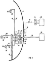
- FIG. 2 In the measuring device shown in FIG. 2, several catalysts 26 'are combined in a central measuring box 44, which is protected inside the security envelope 1 by a wall 46, for example against flying debris. Dilution devices or jet pumps 28 'connected to the measuring box 44 via inflow and outflow lines 30' and 48 are arranged distributed within the safety cover 1.
- the jet pumps 28 ' which are only shown schematically in FIG. 2, are each surrounded by a housing 50 which also serves as a filter.
- Each housing 50 consists at least partially of a gas-permeable material, for example of a sintered metal or a metal fiber braid. This prevents liquid components or coarse contamination with the gas mixture from getting into the jet pumps 28 '.
- the propellant gas led via the propellant gas line 8 is fed to the jet pumps 28 'via the inflow lines 30'.
- the throttles 4 'located in the inflow lines 30' and arranged within the measuring box 44 in turn serve to distribute the propellant gas to the individual jet pumps 28 '.
- the gas mixture reaches the respective jet pumps 28 'via the housing 50 serving as a filter and is mixed with the propellant gas flowing through the inflow lines 30'.
- the gas mixture is dried at the same time so that a condensation of residual moisture contained in the gas mixture, e.g. is safely avoided in cool room areas within the security cover 1.
- the gas mixture thus diluted reaches the respective catalytic converter 26 'via the outflow lines 48.
- the temperature change of each catalytic converter 26 ' is measured separately by means of a temperature sensor 34'.
- the corresponding measurement signals are sent via line 36 to the device 38 for processing the measured values.
- the susceptibility to faults of the assemblies or measuring groups which are distributed within the safety cover 1 and essentially consist of only one jet pump 28 'is particularly low.
Landscapes
- Chemical & Material Sciences (AREA)
- Life Sciences & Earth Sciences (AREA)
- Engineering & Computer Science (AREA)
- Health & Medical Sciences (AREA)
- Analytical Chemistry (AREA)
- General Physics & Mathematics (AREA)
- Medicinal Chemistry (AREA)
- Physics & Mathematics (AREA)
- Combustion & Propulsion (AREA)
- Biochemistry (AREA)
- General Health & Medical Sciences (AREA)
- Food Science & Technology (AREA)
- Immunology (AREA)
- Pathology (AREA)
- Investigating Or Analyzing Materials Using Thermal Means (AREA)
- Investigating Or Analyzing Materials By The Use Of Electric Means (AREA)
- Monitoring And Testing Of Nuclear Reactors (AREA)
- Investigating Or Analyzing Non-Biological Materials By The Use Of Chemical Means (AREA)
Abstract
Claims (9)
- Procédé de détermination de la proportion d'un constituant d'un mélange gazeux dans l'atmosphère de confinement d'une centrale nucléaire,en mesurant la variation de température ayant lieu lors d'une réaction catalytique,
caractérisé en ce qu'il consiste à diluer le mélange gazeux envoyé au catalyseur par un gaz d'entraînement de composition connue, la dilution s'effectuant dans un injecteur (28, 28'). - Procédé suivant la revendication 1,
caractérisé en ce que la dilution est réglable, de préférence dans le rapport 1 : 1 à 1 : 10. - Procédé suivant la revendication 1 ou 2,
caractérisé en ce qu'il consiste à utiliser comme gaz d'entraînement du gaz inerte, de préférence de l'azote. - Procédé suivant l'une des revendications 1 à 3,
caractérisé en ce que le gaz d'entraînement renferme en partie un oxydant, de préférence de l'oxygène. - Procédé suivant l'une des revendications 1 à 3,
caractérisé en ce que le gaz d'entraînement renferme en partie un constituant qui peut être oxydé, de préférence de l'hydrogène ou du monoxyde de carbone. - Procédé suivant l'une des revendications 1 à 5,
caractérisé en ce qu'il consiste à chauffer le catalyseur. - Dispositif pour la mise en oeuvre du procédé suivant l'une des revendications 1 à 6, comprenant des moyens (34, 34') de mesure de la réaction de température ayant lieu lors d'une réaction catalytique,
caractérisé en ce qu'il est prévu, pour la dilution par un gaz d'entraînement de composition connue du mélange gazeux envoyé au catalyseur (26, 26'), un injecteur (28, 28') communiquant du côté de l'entrée avec un conduit (8, 30, 30') pour le gaz d'entraînement et du côté de la sortie avec le catalyseur (26'). - Dispositif suivant la revendication 7,
caractérisé en ce que l'injecteur (28) débouche directement dans le catalyseur (26), un filtre (32) étant monté en aval de l'injecteur. - Dispositif suivant la revendication 7,
caractérisé en ce que l'injecteur (28') est relié au catalyseur (26') par un conduit (48) de sortie et est disposé dans une enveloppe (50) au moins partiellement perméable aux gaz.
Applications Claiming Priority (3)
| Application Number | Priority Date | Filing Date | Title |
|---|---|---|---|
| DE4221692 | 1992-07-02 | ||
| DE4221692A DE4221692A1 (de) | 1992-07-02 | 1992-07-02 | Verfahren und Vorrichtung zur Ermittlung eines Gemischanteils eines Gasgemisches |
| PCT/DE1993/000531 WO1994001767A1 (fr) | 1992-07-02 | 1993-06-21 | Procede et dispositif permettant de determiner une partie d'un melange gazeux |
Publications (2)
| Publication Number | Publication Date |
|---|---|
| EP0648331A1 EP0648331A1 (fr) | 1995-04-19 |
| EP0648331B1 true EP0648331B1 (fr) | 1996-04-24 |
Family
ID=6462304
Family Applications (1)
| Application Number | Title | Priority Date | Filing Date |
|---|---|---|---|
| EP93914590A Expired - Lifetime EP0648331B1 (fr) | 1992-07-02 | 1993-06-21 | Procede et dispositif permettant de determiner une partie d'un melange gazeux |
Country Status (8)
| Country | Link |
|---|---|
| US (1) | US6074882A (fr) |
| EP (1) | EP0648331B1 (fr) |
| JP (1) | JP3226923B2 (fr) |
| CA (1) | CA2139434A1 (fr) |
| DE (2) | DE4221692A1 (fr) |
| RU (1) | RU2115108C1 (fr) |
| UA (1) | UA27913C2 (fr) |
| WO (1) | WO1994001767A1 (fr) |
Families Citing this family (29)
| Publication number | Priority date | Publication date | Assignee | Title |
|---|---|---|---|---|
| DE19704608C1 (de) * | 1997-02-07 | 1998-06-10 | Siemens Ag | Vorrichtung zur Rekombination von Wasserstoff in einem Gasgemisch |
| JP3997642B2 (ja) * | 1999-02-24 | 2007-10-24 | トヨタ自動車株式会社 | 一酸化炭素濃度検出装置および一酸化炭素濃度検出方法 |
| US6932593B2 (en) * | 2001-12-03 | 2005-08-23 | New England Catalytic Technologies, Inc. | Method of preheating catalytic heater |
| DE10303299A1 (de) * | 2003-01-28 | 2004-08-19 | Framatome Anp Gmbh | Schutzsystem, insbesondere für den Primärkreislauf einer kerntechnischen Anlage, und Verfahren zum Betreiben einer kerntechnischen Anlage |
| US7955357B2 (en) | 2004-07-02 | 2011-06-07 | Ellipse Technologies, Inc. | Expandable rod system to treat scoliosis and method of using the same |
| DE102004050308A1 (de) * | 2004-10-14 | 2006-06-14 | Framatome Anp Gmbh | Verfahren und Probenahmesystem zur Gewinnung einer Probe aus der Atmosphäre in einem Reaktorsicherheitsbehälter einer kerntechnischen Anlage |
| US7862502B2 (en) | 2006-10-20 | 2011-01-04 | Ellipse Technologies, Inc. | Method and apparatus for adjusting a gastrointestinal restriction device |
| US20090112263A1 (en) | 2007-10-30 | 2009-04-30 | Scott Pool | Skeletal manipulation system |
| US11202707B2 (en) | 2008-03-25 | 2021-12-21 | Nuvasive Specialized Orthopedics, Inc. | Adjustable implant system |
| US8382756B2 (en) | 2008-11-10 | 2013-02-26 | Ellipse Technologies, Inc. | External adjustment device for distraction device |
| US8197490B2 (en) | 2009-02-23 | 2012-06-12 | Ellipse Technologies, Inc. | Non-invasive adjustable distraction system |
| US9622792B2 (en) | 2009-04-29 | 2017-04-18 | Nuvasive Specialized Orthopedics, Inc. | Interspinous process device and method |
| JP5766917B2 (ja) * | 2010-03-29 | 2015-08-19 | メタウォーター株式会社 | オゾン濃度計 |
| US9248043B2 (en) | 2010-06-30 | 2016-02-02 | Ellipse Technologies, Inc. | External adjustment device for distraction device |
| US8734488B2 (en) | 2010-08-09 | 2014-05-27 | Ellipse Technologies, Inc. | Maintenance feature in magnetic implant |
| WO2012112396A2 (fr) | 2011-02-14 | 2012-08-23 | Ellipse Technologies, Inc. | Dispositif et méthode de traitement d'os fracturés |
| CN102208216B (zh) * | 2011-05-18 | 2013-06-05 | 华北电力大学 | 一种防止氢爆的缓解核电严重事故装置及缓解方法 |
| US10743794B2 (en) | 2011-10-04 | 2020-08-18 | Nuvasive Specialized Orthopedics, Inc. | Devices and methods for non-invasive implant length sensing |
| US10016220B2 (en) | 2011-11-01 | 2018-07-10 | Nuvasive Specialized Orthopedics, Inc. | Adjustable magnetic devices and methods of using same |
| US20130338714A1 (en) | 2012-06-15 | 2013-12-19 | Arvin Chang | Magnetic implants with improved anatomical compatibility |
| CA2889769A1 (fr) | 2012-10-29 | 2014-05-08 | Ellipse Technologies, Inc. | Dispositifs ajustables pour traiter l'arthrite du genou |
| US10751094B2 (en) | 2013-10-10 | 2020-08-25 | Nuvasive Specialized Orthopedics, Inc. | Adjustable spinal implant |
| AU2015253313B9 (en) | 2014-04-28 | 2020-09-10 | Nuvasive Specialized Orthopedics, Inc. | System for informational magnetic feedback in adjustable implants |
| KR20230116081A (ko) | 2014-12-26 | 2023-08-03 | 누베이시브 스페셜라이즈드 오소페딕스, 인크. | 신연을 위한 시스템 및 방법 |
| WO2016134326A2 (fr) | 2015-02-19 | 2016-08-25 | Nuvasive, Inc. | Systèmes et procédés pour ajustement vertébral |
| BR112018007347A2 (pt) | 2015-10-16 | 2018-10-23 | Nuvasive Specialized Orthopedics, Inc. | dispositivos ajustáveis para o tratamento da artrite do joelho |
| AU2016368167B2 (en) | 2015-12-10 | 2021-04-22 | Nuvasive Specialized Orthopedics, Inc. | External adjustment device for distraction device |
| WO2017132646A1 (fr) | 2016-01-28 | 2017-08-03 | Nuvasive Specialized Orthopedics, Inc. | Systèmes de transport osseux |
| JP7777488B2 (ja) * | 2022-04-11 | 2025-11-28 | 矢崎エナジーシステム株式会社 | 熱量計 |
Family Cites Families (23)
| Publication number | Priority date | Publication date | Assignee | Title |
|---|---|---|---|---|
| US1957341A (en) * | 1931-01-21 | 1934-05-01 | Moto Vita Corp | Combustion analyzer |
| US3399398A (en) * | 1965-07-27 | 1968-08-27 | Mine Safety Appliances Co | Combustible gas monitoring system |
| US4170455A (en) * | 1976-03-11 | 1979-10-09 | Rockwell International Corporation | Gas monitoring method and apparatus therefor |
| US4072043A (en) * | 1976-12-20 | 1978-02-07 | Texaco Inc. | Method and system for detecting hydrogen in an inert gas stream |
| US4226675A (en) * | 1977-05-23 | 1980-10-07 | Comsip Delphi, Inc. | Method and apparatus for monitoring and measuring a gas |
| US4298574A (en) * | 1979-06-25 | 1981-11-03 | The Babcock & Wilcox Company | Hydrogen gas detector |
| JPS56118641A (en) * | 1980-02-22 | 1981-09-17 | Nippon Soken Inc | Fine particle discharge amount measuring apparatus for vehicle |
| DE3046560A1 (de) * | 1980-12-10 | 1982-07-15 | Kraftwerk Union AG, 4330 Mülheim | Sonde zur feststellung von brennbaren gasen |
| US4565086A (en) * | 1984-01-20 | 1986-01-21 | Baker Drilling Equipment Company | Method and apparatus for detecting entrained gases in fluids |
| JPS60259740A (ja) * | 1984-06-06 | 1985-12-21 | Toyota Central Res & Dev Lab Inc | 内燃機関の排気浄化方法 |
| DE3438659A1 (de) * | 1984-10-22 | 1986-04-24 | Kraftwerk Union AG, 4330 Mülheim | Sonde mit einem diffusionsmesskopf zum feststellen von gasen |
| JPH0619311B2 (ja) * | 1985-10-19 | 1994-03-16 | 株式会社堀場製作所 | 多成分同時測定用ガス分析装置 |
| US4911890A (en) * | 1986-01-29 | 1990-03-27 | The United States Of America As Represented By The Administrator Of The National Aeronautics And Space Administration | Device for quickly sensing the amount of O2 in a combustion product gas |
| DE3637795A1 (de) * | 1986-11-06 | 1988-05-11 | Siemens Ag | Kernkraftwerk mit einer sicherheitshuelle |
| EP0338324B1 (fr) * | 1988-04-18 | 1993-10-20 | Siemens Aktiengesellschaft | Centrale nucléaire avec confinement de sécurité |
| US5060473A (en) * | 1988-07-13 | 1991-10-29 | Nissan Motor Company, Limited | System for detecting deterioration of catalyst in catalytic converter |
| JPH0729494Y2 (ja) * | 1989-07-12 | 1995-07-05 | 株式会社堀場製作所 | 水素ガス分析装置 |
| US5167927A (en) * | 1989-10-31 | 1992-12-01 | Karlson Eskil L | Monitor for ozone, hydrogen peroxide and other gases in fluids |
| DE4003833A1 (de) * | 1990-01-08 | 1991-07-11 | Grs Ges Fuer Reaktorsicherheit | Vorrichtung zur entfernung von wasserstoff aus einem wasserstoff, sauerstoff, dampf und aerosole enthaltenden gasgemisch |
| US5133184A (en) * | 1990-02-10 | 1992-07-28 | Volkswagen Ag | Method and apparatus for monitoring the conversion ratio of a catalytic converter |
| DE4040734A1 (de) * | 1990-06-21 | 1992-01-02 | Siemens Ag | Verfahren und einrichtung zur oxidation von wasserstoff |
| AT393173B (de) * | 1990-08-14 | 1991-08-26 | Steyr Nutzfahrzeuge | Anlage zur schadstoffanalyse, insbesondere partikelemission, von dieselmotorenabgas, mit einer speziellen teilstromverduennungseinrichtung |
| US5374400A (en) * | 1992-05-07 | 1994-12-20 | The United States Of America As Represented By The Administrator Of The National Aeronautics And Space Administration | Two-stage gas measurement system |
-
1992
- 1992-07-02 DE DE4221692A patent/DE4221692A1/de not_active Withdrawn
-
1993
- 1993-06-21 CA CA002139434A patent/CA2139434A1/fr not_active Abandoned
- 1993-06-21 UA UA94129252A patent/UA27913C2/uk unknown
- 1993-06-21 EP EP93914590A patent/EP0648331B1/fr not_active Expired - Lifetime
- 1993-06-21 DE DE59302383T patent/DE59302383D1/de not_active Expired - Fee Related
- 1993-06-21 WO PCT/DE1993/000531 patent/WO1994001767A1/fr not_active Ceased
- 1993-06-21 RU RU94046345/25A patent/RU2115108C1/ru not_active IP Right Cessation
- 1993-06-21 JP JP50280894A patent/JP3226923B2/ja not_active Expired - Fee Related
-
1996
- 1996-10-24 US US08/736,372 patent/US6074882A/en not_active Expired - Fee Related
Also Published As
| Publication number | Publication date |
|---|---|
| DE4221692A1 (de) | 1994-01-05 |
| CA2139434A1 (fr) | 1994-01-20 |
| RU2115108C1 (ru) | 1998-07-10 |
| JPH07508588A (ja) | 1995-09-21 |
| RU94046345A (ru) | 1996-10-20 |
| US6074882A (en) | 2000-06-13 |
| DE59302383D1 (de) | 1996-05-30 |
| JP3226923B2 (ja) | 2001-11-12 |
| UA27913C2 (uk) | 2000-10-16 |
| EP0648331A1 (fr) | 1995-04-19 |
| WO1994001767A1 (fr) | 1994-01-20 |
Similar Documents
| Publication | Publication Date | Title |
|---|---|---|
| EP0648331B1 (fr) | Procede et dispositif permettant de determiner une partie d'un melange gazeux | |
| EP0670490B1 (fr) | Méthode et appareil pour la mesure d'un milieu gazeux avec un détecteur chimique | |
| DE69117289T2 (de) | Stickoxyd-sensoraufbau | |
| DE1809622C2 (de) | Meßsonde zum Erfassen von Gasgehalten | |
| DE19851949C1 (de) | Sensor für die Untersuchung von Abgasen und Untersuchungsverfahren | |
| DE3135101C2 (fr) | ||
| DE2801060A1 (de) | Chromatographisches system und chromatographisches analysenverfahren | |
| DE69909939T2 (de) | Analysegerät zur kontinuierlichen messung von h2s in einem gas und dessen verwendung in einer vorrichtung zur regelung der injizierten luftmenge in einen oxydationsreaktor zur umsetzung von h2s zu schwefel | |
| DE2524597A1 (de) | Verfahren und vorrichtung zum aufspueren eines gases | |
| DE2801081A1 (de) | Chromatographisches system und chromatographisches analysenverfahren | |
| DE19702570A1 (de) | Sauerstoffsensor des Grenzstromtyps | |
| DE1598351B2 (de) | Verfahren zur Bestimmung des Sauerstoffbedarfs einer wäßrigen Dispersion und Vorrichtung zur Durchführung des Verfahrens | |
| DE69017775T2 (de) | Wasserstoffprüfgerät. | |
| DE2261456B2 (de) | Pyrolytische analyse von fluessigkeiten | |
| DE2738755C3 (de) | Elektrochemische Meßzelle | |
| DE19746446C2 (de) | Verfahren zur Verdünnung von Proben für ein Chemilumineszenzanalysegerät und zur Anwendung des Verfahrens geeignetes Chemilumineszenzanalysegerät | |
| EP0298240B1 (fr) | Procédé et dispositif de surveillance de la teneur en substances nocives dans les gaz d'échappement de machines à combustion | |
| EP0809109B1 (fr) | Appareil pour la mesure de composants de gaz d'échappement d'une machine à combustion | |
| EP0239106B1 (fr) | Procédé pour réduire la quantité de N0x dans des gaz, dans lequel un courant de gaz NH3 est ajouté en continu | |
| DE1176399B (de) | Verfahren zum Messen eines dem Sauerstoff-gehalt einer natuerlichen oder kuenstlichen Atmosphaere proportionalen Waermemengen-Messwertes und Vorrichtung zur Anzeige desSauerstoffgehaltes solcher Atmosphaeren | |
| DE2904872A1 (de) | Verfahren zur erzeugung eines no/no tief 2 -pruefgasgemisches sowie vorrichtung zu seiner durchfuehrung | |
| DE102006031206B4 (de) | Verfahren zur Herstellung eines Kalibrieraerosols für die Anzahlkonzentration luftgetragener Partikeln und Kalibrieraerosolgenerator | |
| DE2950261A1 (de) | Verfahren und vorrichtung zur ueberwachung chemischer vorgaenge | |
| DE2348090C2 (de) | Verfahren zur kontinuierlichen Überführung von in einer Flüssigkeit gelösten Gaskomponenten in ein Trägergas | |
| DE3938056C2 (de) | Sauerstoffühler |
Legal Events
| Date | Code | Title | Description |
|---|---|---|---|
| PUAI | Public reference made under article 153(3) epc to a published international application that has entered the european phase |
Free format text: ORIGINAL CODE: 0009012 |
|
| 17P | Request for examination filed |
Effective date: 19941108 |
|
| AK | Designated contracting states |
Kind code of ref document: A1 Designated state(s): BE DE FR SE |
|
| 17Q | First examination report despatched |
Effective date: 19951012 |
|
| GRAH | Despatch of communication of intention to grant a patent |
Free format text: ORIGINAL CODE: EPIDOS IGRA |
|
| GRAA | (expected) grant |
Free format text: ORIGINAL CODE: 0009210 |
|
| AK | Designated contracting states |
Kind code of ref document: B1 Designated state(s): BE DE FR SE |
|
| REF | Corresponds to: |
Ref document number: 59302383 Country of ref document: DE Date of ref document: 19960530 |
|
| ET | Fr: translation filed | ||
| PLBE | No opposition filed within time limit |
Free format text: ORIGINAL CODE: 0009261 |
|
| STAA | Information on the status of an ep patent application or granted ep patent |
Free format text: STATUS: NO OPPOSITION FILED WITHIN TIME LIMIT |
|
| 26N | No opposition filed | ||
| PGFP | Annual fee paid to national office [announced via postgrant information from national office to epo] |
Ref country code: DE Payment date: 20020327 Year of fee payment: 10 |
|
| PGFP | Annual fee paid to national office [announced via postgrant information from national office to epo] |
Ref country code: FR Payment date: 20020617 Year of fee payment: 10 |
|
| PGFP | Annual fee paid to national office [announced via postgrant information from national office to epo] |
Ref country code: BE Payment date: 20020620 Year of fee payment: 10 |
|
| PGFP | Annual fee paid to national office [announced via postgrant information from national office to epo] |
Ref country code: SE Payment date: 20020624 Year of fee payment: 10 |
|
| PG25 | Lapsed in a contracting state [announced via postgrant information from national office to epo] |
Ref country code: SE Free format text: LAPSE BECAUSE OF NON-PAYMENT OF DUE FEES Effective date: 20030622 |
|
| PG25 | Lapsed in a contracting state [announced via postgrant information from national office to epo] |
Ref country code: BE Free format text: LAPSE BECAUSE OF NON-PAYMENT OF DUE FEES Effective date: 20030630 |
|
| BERE | Be: lapsed |
Owner name: *FRAMATOME ANP G.M.B.H. Effective date: 20030630 |
|
| PG25 | Lapsed in a contracting state [announced via postgrant information from national office to epo] |
Ref country code: DE Free format text: LAPSE BECAUSE OF NON-PAYMENT OF DUE FEES Effective date: 20040101 |
|
| EUG | Se: european patent has lapsed | ||
| PG25 | Lapsed in a contracting state [announced via postgrant information from national office to epo] |
Ref country code: FR Free format text: LAPSE BECAUSE OF NON-PAYMENT OF DUE FEES Effective date: 20040227 |
|
| REG | Reference to a national code |
Ref country code: FR Ref legal event code: ST |