EP0648510A1 - Dispositif de seringue pour stockage et application d'un matériau à composants multiples, dispositif pour actionner celui-ci - Google Patents
Dispositif de seringue pour stockage et application d'un matériau à composants multiples, dispositif pour actionner celui-ci Download PDFInfo
- Publication number
- EP0648510A1 EP0648510A1 EP94890154A EP94890154A EP0648510A1 EP 0648510 A1 EP0648510 A1 EP 0648510A1 EP 94890154 A EP94890154 A EP 94890154A EP 94890154 A EP94890154 A EP 94890154A EP 0648510 A1 EP0648510 A1 EP 0648510A1
- Authority
- EP
- European Patent Office
- Prior art keywords
- syringe
- bodies
- unit
- piston
- plugs
- Prior art date
- Legal status (The legal status is an assumption and is not a legal conclusion. Google has not performed a legal analysis and makes no representation as to the accuracy of the status listed.)
- Granted
Links
- 239000000463 material Substances 0.000 title claims abstract description 37
- 238000011049 filling Methods 0.000 claims abstract description 32
- 239000004033 plastic Substances 0.000 claims abstract description 3
- 229920003023 plastic Polymers 0.000 claims abstract description 3
- 230000001681 protective effect Effects 0.000 claims description 23
- 238000004519 manufacturing process Methods 0.000 claims description 18
- 238000002347 injection Methods 0.000 claims description 8
- 239000007924 injection Substances 0.000 claims description 8
- 238000002372 labelling Methods 0.000 claims description 8
- 238000000034 method Methods 0.000 claims description 6
- XECAHXYUAAWDEL-UHFFFAOYSA-N acrylonitrile butadiene styrene Chemical compound C=CC=C.C=CC#N.C=CC1=CC=CC=C1 XECAHXYUAAWDEL-UHFFFAOYSA-N 0.000 claims description 5
- 229920000122 acrylonitrile butadiene styrene Polymers 0.000 claims description 5
- 239000004676 acrylonitrile butadiene styrene Substances 0.000 claims description 5
- 229920001296 polysiloxane Polymers 0.000 claims description 5
- 239000004743 Polypropylene Substances 0.000 claims description 4
- -1 polypropylene Polymers 0.000 claims description 4
- 229920001155 polypropylene Polymers 0.000 claims description 4
- 238000007789 sealing Methods 0.000 claims description 4
- 238000003860 storage Methods 0.000 claims description 4
- 230000005764 inhibitory process Effects 0.000 claims 1
- 239000003106 tissue adhesive Substances 0.000 abstract description 11
- 238000002156 mixing Methods 0.000 description 10
- 238000011109 contamination Methods 0.000 description 6
- 238000013461 design Methods 0.000 description 6
- 210000003811 finger Anatomy 0.000 description 6
- 238000004806 packaging method and process Methods 0.000 description 6
- 239000000243 solution Substances 0.000 description 6
- 239000007921 spray Substances 0.000 description 5
- 230000001954 sterilising effect Effects 0.000 description 4
- 238000004659 sterilization and disinfection Methods 0.000 description 4
- 238000011282 treatment Methods 0.000 description 4
- 108090000190 Thrombin Proteins 0.000 description 3
- 230000036512 infertility Effects 0.000 description 3
- 239000012460 protein solution Substances 0.000 description 3
- 229960004072 thrombin Drugs 0.000 description 3
- 108010071289 Factor XIII Proteins 0.000 description 2
- 108010049003 Fibrinogen Proteins 0.000 description 2
- 102000008946 Fibrinogen Human genes 0.000 description 2
- 239000003708 ampul Substances 0.000 description 2
- 235000021120 animal protein Nutrition 0.000 description 2
- 239000012295 chemical reaction liquid Substances 0.000 description 2
- 238000010276 construction Methods 0.000 description 2
- 230000000694 effects Effects 0.000 description 2
- 229940012444 factor xiii Drugs 0.000 description 2
- 230000002349 favourable effect Effects 0.000 description 2
- 229940012952 fibrinogen Drugs 0.000 description 2
- 238000005429 filling process Methods 0.000 description 2
- 238000001746 injection moulding Methods 0.000 description 2
- 238000003780 insertion Methods 0.000 description 2
- 230000037431 insertion Effects 0.000 description 2
- NOESYZHRGYRDHS-UHFFFAOYSA-N insulin Chemical compound N1C(=O)C(NC(=O)C(CCC(N)=O)NC(=O)C(CCC(O)=O)NC(=O)C(C(C)C)NC(=O)C(NC(=O)CN)C(C)CC)CSSCC(C(NC(CO)C(=O)NC(CC(C)C)C(=O)NC(CC=2C=CC(O)=CC=2)C(=O)NC(CCC(N)=O)C(=O)NC(CC(C)C)C(=O)NC(CCC(O)=O)C(=O)NC(CC(N)=O)C(=O)NC(CC=2C=CC(O)=CC=2)C(=O)NC(CSSCC(NC(=O)C(C(C)C)NC(=O)C(CC(C)C)NC(=O)C(CC=2C=CC(O)=CC=2)NC(=O)C(CC(C)C)NC(=O)C(C)NC(=O)C(CCC(O)=O)NC(=O)C(C(C)C)NC(=O)C(CC(C)C)NC(=O)C(CC=2NC=NC=2)NC(=O)C(CO)NC(=O)CNC2=O)C(=O)NCC(=O)NC(CCC(O)=O)C(=O)NC(CCCNC(N)=N)C(=O)NCC(=O)NC(CC=3C=CC=CC=3)C(=O)NC(CC=3C=CC=CC=3)C(=O)NC(CC=3C=CC(O)=CC=3)C(=O)NC(C(C)O)C(=O)N3C(CCC3)C(=O)NC(CCCCN)C(=O)NC(C)C(O)=O)C(=O)NC(CC(N)=O)C(O)=O)=O)NC(=O)C(C(C)CC)NC(=O)C(CO)NC(=O)C(C(C)O)NC(=O)C1CSSCC2NC(=O)C(CC(C)C)NC(=O)C(NC(=O)C(CCC(N)=O)NC(=O)C(CC(N)=O)NC(=O)C(NC(=O)C(N)CC=1C=CC=CC=1)C(C)C)CC1=CN=CN1 NOESYZHRGYRDHS-UHFFFAOYSA-N 0.000 description 2
- 239000000314 lubricant Substances 0.000 description 2
- 238000012986 modification Methods 0.000 description 2
- 230000004048 modification Effects 0.000 description 2
- 239000011343 solid material Substances 0.000 description 2
- 238000003466 welding Methods 0.000 description 2
- 108090000790 Enzymes Proteins 0.000 description 1
- 102000004190 Enzymes Human genes 0.000 description 1
- 102000004877 Insulin Human genes 0.000 description 1
- 108090001061 Insulin Proteins 0.000 description 1
- 241001465754 Metazoa Species 0.000 description 1
- 239000011358 absorbing material Substances 0.000 description 1
- 230000015572 biosynthetic process Effects 0.000 description 1
- 239000008280 blood Substances 0.000 description 1
- 210000004369 blood Anatomy 0.000 description 1
- 238000005266 casting Methods 0.000 description 1
- 239000004568 cement Substances 0.000 description 1
- 230000003749 cleanliness Effects 0.000 description 1
- 230000015271 coagulation Effects 0.000 description 1
- 238000005345 coagulation Methods 0.000 description 1
- 150000001875 compounds Chemical class 0.000 description 1
- 238000001816 cooling Methods 0.000 description 1
- 238000010586 diagram Methods 0.000 description 1
- 229920001971 elastomer Polymers 0.000 description 1
- 238000004049 embossing Methods 0.000 description 1
- 238000005516 engineering process Methods 0.000 description 1
- 229940088598 enzyme Drugs 0.000 description 1
- 230000023597 hemostasis Effects 0.000 description 1
- 238000011065 in-situ storage Methods 0.000 description 1
- 229940125396 insulin Drugs 0.000 description 1
- 239000002184 metal Substances 0.000 description 1
- 210000000056 organ Anatomy 0.000 description 1
- 238000012858 packaging process Methods 0.000 description 1
- 238000012856 packing Methods 0.000 description 1
- 239000004014 plasticizer Substances 0.000 description 1
- 230000003014 reinforcing effect Effects 0.000 description 1
- 229920002379 silicone rubber Polymers 0.000 description 1
- 239000004945 silicone rubber Substances 0.000 description 1
- 239000007787 solid Substances 0.000 description 1
- 238000007711 solidification Methods 0.000 description 1
- 230000008023 solidification Effects 0.000 description 1
- 238000012859 sterile filling Methods 0.000 description 1
- 239000000126 substance Substances 0.000 description 1
- 210000003813 thumb Anatomy 0.000 description 1
- 238000002604 ultrasonography Methods 0.000 description 1
Images


Classifications
-
- A—HUMAN NECESSITIES
- A61—MEDICAL OR VETERINARY SCIENCE; HYGIENE
- A61B—DIAGNOSIS; SURGERY; IDENTIFICATION
- A61B17/00—Surgical instruments, devices or methods
- A61B17/00491—Surgical glue applicators
-
- A—HUMAN NECESSITIES
- A61—MEDICAL OR VETERINARY SCIENCE; HYGIENE
- A61M—DEVICES FOR INTRODUCING MEDIA INTO, OR ONTO, THE BODY; DEVICES FOR TRANSDUCING BODY MEDIA OR FOR TAKING MEDIA FROM THE BODY; DEVICES FOR PRODUCING OR ENDING SLEEP OR STUPOR
- A61M5/00—Devices for bringing media into the body in a subcutaneous, intra-vascular or intramuscular way; Accessories therefor, e.g. filling or cleaning devices, arm-rests
- A61M5/178—Syringes
- A61M5/19—Syringes having more than one chamber, e.g. including a manifold coupling two parallelly aligned syringes through separate channels to a common discharge assembly
-
- A—HUMAN NECESSITIES
- A61—MEDICAL OR VETERINARY SCIENCE; HYGIENE
- A61M—DEVICES FOR INTRODUCING MEDIA INTO, OR ONTO, THE BODY; DEVICES FOR TRANSDUCING BODY MEDIA OR FOR TAKING MEDIA FROM THE BODY; DEVICES FOR PRODUCING OR ENDING SLEEP OR STUPOR
- A61M5/00—Devices for bringing media into the body in a subcutaneous, intra-vascular or intramuscular way; Accessories therefor, e.g. filling or cleaning devices, arm-rests
- A61M5/50—Devices for bringing media into the body in a subcutaneous, intra-vascular or intramuscular way; Accessories therefor, e.g. filling or cleaning devices, arm-rests having means for preventing re-use, or for indicating if defective, used, tampered with or unsterile
- A61M5/5066—Means for preventing re-use by disconnection of piston and piston-rod
-
- B—PERFORMING OPERATIONS; TRANSPORTING
- B05—SPRAYING OR ATOMISING IN GENERAL; APPLYING FLUENT MATERIALS TO SURFACES, IN GENERAL
- B05C—APPARATUS FOR APPLYING FLUENT MATERIALS TO SURFACES, IN GENERAL
- B05C17/00—Hand tools or apparatus using hand held tools, for applying liquids or other fluent materials to, for spreading applied liquids or other fluent materials on, or for partially removing applied liquids or other fluent materials from, surfaces
- B05C17/005—Hand tools or apparatus using hand held tools, for applying liquids or other fluent materials to, for spreading applied liquids or other fluent materials on, or for partially removing applied liquids or other fluent materials from, surfaces for discharging material from a reservoir or container located in or on the hand tool through an outlet orifice by pressure without using surface contacting members like pads or brushes
- B05C17/00593—Hand tools of the syringe type
-
- B—PERFORMING OPERATIONS; TRANSPORTING
- B65—CONVEYING; PACKING; STORING; HANDLING THIN OR FILAMENTARY MATERIAL
- B65D—CONTAINERS FOR STORAGE OR TRANSPORT OF ARTICLES OR MATERIALS, e.g. BAGS, BARRELS, BOTTLES, BOXES, CANS, CARTONS, CRATES, DRUMS, JARS, TANKS, HOPPERS, FORWARDING CONTAINERS; ACCESSORIES, CLOSURES, OR FITTINGS THEREFOR; PACKAGING ELEMENTS; PACKAGES
- B65D81/00—Containers, packaging elements, or packages, for contents presenting particular transport or storage problems, or adapted to be used for non-packaging purposes after removal of contents
- B65D81/32—Containers, packaging elements, or packages, for contents presenting particular transport or storage problems, or adapted to be used for non-packaging purposes after removal of contents for packaging two or more different materials which must be maintained separate prior to use in admixture
- B65D81/325—Containers having parallel or coaxial compartments, provided with a piston or a movable bottom for discharging contents
-
- A—HUMAN NECESSITIES
- A61—MEDICAL OR VETERINARY SCIENCE; HYGIENE
- A61B—DIAGNOSIS; SURGERY; IDENTIFICATION
- A61B17/00—Surgical instruments, devices or methods
- A61B17/00491—Surgical glue applicators
- A61B2017/00495—Surgical glue applicators for two-component glue
-
- A—HUMAN NECESSITIES
- A61—MEDICAL OR VETERINARY SCIENCE; HYGIENE
- A61M—DEVICES FOR INTRODUCING MEDIA INTO, OR ONTO, THE BODY; DEVICES FOR TRANSDUCING BODY MEDIA OR FOR TAKING MEDIA FROM THE BODY; DEVICES FOR PRODUCING OR ENDING SLEEP OR STUPOR
- A61M5/00—Devices for bringing media into the body in a subcutaneous, intra-vascular or intramuscular way; Accessories therefor, e.g. filling or cleaning devices, arm-rests
- A61M5/178—Syringes
- A61M5/31—Details
- A61M2005/3103—Leak prevention means for distal end of syringes, i.e. syringe end for mounting a needle
- A61M2005/3104—Caps for syringes without needle
-
- A—HUMAN NECESSITIES
- A61—MEDICAL OR VETERINARY SCIENCE; HYGIENE
- A61M—DEVICES FOR INTRODUCING MEDIA INTO, OR ONTO, THE BODY; DEVICES FOR TRANSDUCING BODY MEDIA OR FOR TAKING MEDIA FROM THE BODY; DEVICES FOR PRODUCING OR ENDING SLEEP OR STUPOR
- A61M5/00—Devices for bringing media into the body in a subcutaneous, intra-vascular or intramuscular way; Accessories therefor, e.g. filling or cleaning devices, arm-rests
- A61M5/178—Syringes
- A61M5/31—Details
- A61M5/315—Pistons; Piston-rods; Guiding, blocking or restricting the movement of the rod or piston; Appliances on the rod for facilitating dosing ; Dosing mechanisms
- A61M5/31501—Means for blocking or restricting the movement of the rod or piston
- A61M2005/31508—Means for blocking or restricting the movement of the rod or piston provided on the piston-rod
-
- A—HUMAN NECESSITIES
- A61—MEDICAL OR VETERINARY SCIENCE; HYGIENE
- A61M—DEVICES FOR INTRODUCING MEDIA INTO, OR ONTO, THE BODY; DEVICES FOR TRANSDUCING BODY MEDIA OR FOR TAKING MEDIA FROM THE BODY; DEVICES FOR PRODUCING OR ENDING SLEEP OR STUPOR
- A61M2207/00—Methods of manufacture, assembly or production
-
- B—PERFORMING OPERATIONS; TRANSPORTING
- B05—SPRAYING OR ATOMISING IN GENERAL; APPLYING FLUENT MATERIALS TO SURFACES, IN GENERAL
- B05C—APPARATUS FOR APPLYING FLUENT MATERIALS TO SURFACES, IN GENERAL
- B05C17/00—Hand tools or apparatus using hand held tools, for applying liquids or other fluent materials to, for spreading applied liquids or other fluent materials on, or for partially removing applied liquids or other fluent materials from, surfaces
- B05C17/005—Hand tools or apparatus using hand held tools, for applying liquids or other fluent materials to, for spreading applied liquids or other fluent materials on, or for partially removing applied liquids or other fluent materials from, surfaces for discharging material from a reservoir or container located in or on the hand tool through an outlet orifice by pressure without using surface contacting members like pads or brushes
- B05C17/00503—Details of the outlet element
- B05C17/00516—Shape or geometry of the outlet orifice or the outlet element
Definitions
- the invention relates to a syringe set for the storage and application of a biological multi-component material, preferably a tissue adhesive based on human or animal proteins for the seamless or seam-supporting connection of human or animal tissue or organ parts, for wound sealing, hemostasis and the like
- Syringe device which has a plurality of parallel syringe bodies which are connected to one another by a connecting part and which are filled with the individual components of the multicomponent material and which are closed by pistons, an actuating device for this syringe device which has piston rods assigned to the pistons and a common handle part, and one contains dispensing part which can be plugged onto the cones of the syringe body.
- the invention further relates to a syringe device for storing and applying a biological multi-component material, with a plurality of parallel syringe bodies, preferably made of plastic material, which are connected to one another by a connecting part, for the different components of the multi-component material, the syringe bodies forming an integral syringe unit with the connecting part.
- the invention correspondingly relates to an actuating device for a syringe device for storing and applying a multi-component material with a plurality of parallel syringe bodies connected to one another and closed by pistons, consisting of piston rods assigned to the syringe body pistons and a common grip part.
- the invention also relates to a method for producing a filled, sterile syringe device.
- tissue adhesive which is solidified in situ by contact with blood coagulation-promoting coagulation enzymes
- the components used being a protein solution (tissue adhesive) containing factor XIII and fibrinogen on the one hand and a solution containing thrombin on the other.
- tissue adhesive tissue adhesive
- these components are applied to the desired location, for example a wound site to be treated or protected, over the dispensing part connected to the syringe bodies of the syringe device by plugging onto their syringe cones - for example the connection head with a mixing cannula or the spray head.
- a generally trough-shaped or sleeve-shaped holding device with corresponding troughs or troughs for receiving the syringe body is provided for connecting the syringe body, this holding device also being provided with finger grips protruding laterally in opposite directions.
- the syringe bodies are inserted into this holding device, e.g. elastic snap-off projections hold the syringe body.
- the plunger rods which are firmly connected to the plunger, are further connected to a common handle part, and it has also been proposed to connect a guide rod to the common grip part to stabilize or improve the guidance of the plunger rods when the syringe device is actuated; this guide rod extends through a guide hole in the holding device.
- Syringe bodies which are in direct contact with one another on the longitudinal side, are connected to one another in a complex manner by means of a cement compound and by wire loops and rubber bands.
- the syringe bodies are connected to one another by a clamp enclosing them at a central point, the syringe bodies not taking a stable position relative to one another.
- the two piston rods must be advanced by the user together and as evenly as possible, which requires great skill.
- the known application sets still require a relatively high level of production costs, since apart from the syringe bodies for the syringe device and the piston with piston rods and actuating device, several separate components, namely the holding device on the one hand and the common handle part together with the guide rod on the other hand, have to be produced, these components must then be manually connected to the corresponding parts.
- the syringe assembly of the type mentioned at the outset is characterized in that the filled syringe bodies, which are closed by separate plunger plugs, form an integral syringe unit with the connecting part, and in that furthermore, the connecting part at one of the ends of the syringe unit, preferably at the end opposite the cones, leaves a recess between the syringe bodies for receiving a protective part which shields the other syringe body or bodies when filling the syringe body, and in that the handle part is integrally connected to the piston rods and thereby a one-piece piston rod unit is formed separately from the syringe unit with the piston plugs.
- the syringe device according to the invention of the type specified at the outset is characterized in that the connecting part at one of the ends of the syringe unit, preferably at the end opposite the cones, has a recess between the syringe bodies for receiving a protective part which shields the other syringe body or bodies when filling the syringe body releases.
- the actuating device according to the invention of the type mentioned at the outset is characterized in that the grip part is connected in one piece to the piston rods, and in this way an integral piston rod unit is formed.
- the method according to the invention is characterized in that the syringe bodies of a sterile syringe unit, which were produced and kept sterile in one piece or were sterilized after their manufacture, and from which the one syringe body ends were sealed, after the introduction of one or the other Protective part protecting the syringe body into the recess between the (respective) syringe bodies at the other end in a filling system is filled mechanically and under sterile conditions with the components of the biological multi-component material and then closed with sterile plunger stoppers.
- the syringe device is formed by a compact, stable syringe unit, to which an equally compact, stable piston rod unit is assigned. Both units can be produced completely automatically without any problems, ie molded in one piece, which is particularly important in the case of the syringe unit with regard to the desired sterility and "particle-free".
- the piston rod unit similar to that for the discharge part, Subsequent sterilization in the already packaged state is possible without any problems, ie it is not necessary to manufacture the piston rod unit in the sterile area or to insert it into the syringe unit.
- the piston rod unit can also be packed together with the delivery part (for example a connection piece with separate channels for conveying the individual components, possibly with a mixing cannula) in a common packaging and subsequently subjected to a sterilization treatment.
- the syringe units can carry out all processes from manufacture, preferably by injection molding, over any packing and unpacking of the syringe unit in between, and individualization of the syringe units for mechanical filling of the syringe bodies up to their closing by means of the piston stopper and packaging to run aseptically, with no manual intervention required.
- This is a very important advantage, particularly with regard to the materials to be applied, namely protein solutions, etc., which are preferably used.
- the syringe device according to the invention still empty or already filled, is thus characterized in every stage in that it is sterile.
- a protective part for example in the form of a cover bracket, is provided to prevent mutual contamination with the components or reaction liquids, which protrudes into the receiving recess between the (respective) syringe bodies and thereby the other syringe body (s) from the straight separates and shields the filled syringe body.
- a protective plate or similar protective part between the syringe bodies into the receptacle in such a way that the syringe bodies are filled simultaneously on both sides of this protective part, in which case mutual contamination by this protective part is also effectively prevented.
- this feature of the receiving recess between the syringe bodies for the protective part to be inserted during filling contributes significantly to the possibility of sterile machine filling, the simple, one-piece, compact design of the syringe unit being guaranteed nonetheless.
- the syringe unit, the piston rod unit and / or the dispensing part can expediently be used at least in regions, e.g. in the form of a strip, have X-ray absorbing material; for example, a metal strip can be molded in. In this way, possible later location by means of an X-ray device is possible.
- the separate plunger plugs can consist entirely of silicone material, which is advantageous with regard to the desired sliding properties over long periods (e.g. 2 years) and the required cleanliness (e.g. no lubricant may be used).
- piston plugs are used which consist of solid material and are spherical. Such piston plugs have only one sealing lip, which facilitates the advancement of the piston plugs in the direction of the cones. Another advantage of this embodiment is that after the syringe body has been filled, the plunger plugs can be inserted in a simple manner, since no special alignment of the plunger plugs is necessary.
- US-A-5 147 323 discloses an ampoule unit with a plurality of ampoules arranged side by side in a box-shaped container, which are closed on the back by simple, loose piston plugs; Depending on the position of a sliding lid closing the container and having an opening for inserting a piston rod, the piston stopper in one of the ampoules can be pressed forward in order to ultimately deliver a dose of insulin via an extendable needle.
- this known ampoule unit is extremely complex and complex and hardly suitable for the applications of a tissue adhesive.
- the syringe unit can be flat and plate-shaped for easy handling, with a thickness corresponding to the thickness or the outer diameter of the syringe body.
- Such a flat, compact, plate-shaped syringe unit is of course favorable for any kind of manipulation, apart from the fact that this syringe unit has a particularly high breaking strength.
- the connecting webs with thicknesses comparable to the wall thickness of the syringe body can be produced without any problems, so that no difficulties arise during the production by casting or the like.
- An advantageous embodiment of the device according to the invention is accordingly characterized in that when syringe bodies with different cross-sectional areas and constant piston stroke length are provided, the cross-sectional area of at least one syringe body is oval, its dimension transverse to the thickness direction of the plate-shaped syringe unit being different from that of the cross-sectional area of the other syringe body is different.
- At least one connecting web is provided as a connecting part which extends in the form of a plate in accordance with a central plane defined by the longitudinal axes of the syringe bodies and connects centrally to the respective syringe body.
- finger grips are provided on the trough-shaped holding device in the known syringe devices of the type in question, which protrude laterally and in opposite directions from the holding device relative to the syringe bodies.
- Finger grips can of course also be provided in the syringe device according to the invention, it being expedient to simply form the finger grips directly on the rear ends of the syringe bodies.
- the finger grips can have a width comparable to the outer diameter of the syringe body, so that in the case of the particularly preferred ones flat, plate-shaped design of the syringe unit lie within the thickness dimension of the syringe unit.
- the syringe unit is a one-piece polypropylene injection molded part.
- Polypropylene is particularly suitable for the manufacture of the syringe body, since it has no so-called "triggering" property, i.e. no components, such as plasticizers etc., go from the material into the syringe content, i.e. into the respective product contained in the syringe bodies.
- the or at least one connecting part has at least one labeling field.
- a label for example relating to the content of the syringe body, the method of application, etc.
- a label for example relating to the content of the syringe body, the method of application, etc.
- a label can be attached to this labeling field before or after filling the syringe body.
- it is conceivable to provide an imprint directly on the inscription field for the inscription, or an inscription label or the like can be applied, e.g. be stuck on.
- a stiffening web extending between the piston rods and firmly connected to them is provided.
- the piston rod unit is a one-piece injection molded part.
- the actuating device or piston rod unit is only inserted into the syringe device at a later point in time, after filling the syringe body and closing it by inserting the piston stopper, in particular only immediately before use.
- the result is that the piston rod unit does not come into direct contact with the products contained in the syringe bodies.
- the choice of material for the piston rod unit is not so critical, and the material can be selected here primarily in view of the desired simple manufacture and the high strength desired for the piston rod unit.
- the piston rod unit consists of acrylonitrile-butadiene-styrene copolymer (ABS).
- the syringe device When manufacturing the filled syringe device while maintaining sterility, it is also particularly advantageous if the syringe device is sterile packed immediately after filling with the components and sealing with the plunger stopper. Furthermore, it is advantageous if the syringe bodies corresponding to one another of a plurality of syringe units arranged in a row are simultaneously filled sterile by introducing (in each case) a common protective part into the recesses of these syringe units.
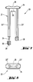
- the syringe device 1 shows a syringe device, generally designated 1, as part of a syringe set for storing and applying a tissue adhesive based on human or animal proteins.
- the syringe device 1 contains two syringe bodies 2, 3, one of which is used to hold a solution containing thrombin and the second to hold a solution containing factor XIII and fibrinogen.
- the syringe bodies 2, 3, as can be seen from FIGS. 2 and 3, have a circular cross section in the exemplary embodiment shown, and they each have a syringe cone 4 or 5 at their front ends in a conventional manner, which, until put into use, by a closure cap (not shown in FIG. 1, but see cap 45 in FIGS.
- a dispensing part for example a plug-on or collecting head with a mixing cannula (see FIG. 15 to be explained below), a connecting piece with a cannula or a spray head, is placed on the syringe cones 4, 5 when used as a further syringe set part. put on, as is known per se.
- Finger handles 8, 9 are formed directly on the rear end of the syringe bodies 2, 3 and project laterally from the syringe bodies 2, 3 in opposite directions.
- the syringe bodies 2, 3 are connected to one another by a front-side and a rear-side connecting web 10 or 11 (see also FIGS. 2 and 3) to form a solid, non-separable, compact, flat, plate-shaped unit.
- These connecting webs 10, 11 are connected with their outside tangentially to the outside of the cylindrical syringe bodies 2, 3, and they extend almost over the entire length of the syringe bodies 2, 3, but each end at a distance from the front end (syringe cone end) or rear end (where the syringe bodies 2, 3 are provided with a chamfer 12 or 13), so that 14 recesses 16 and 17 for both at the front end and at the rear end of the syringe unit formed by connecting the syringe bodies 2, 3 Insertion of a protective part, for example in the form of an angled cover plate, as will be explained in more detail below with reference to FIGS. 9, 9A and 9B, are left free when the syringe bodies 2, 3 are filled
- the connecting webs 10, 11 are formed in one piece with the syringe bodies 2, 3, in particular injection molded, polypropylene being the preferred material for the one-piece syringe unit 14.
- one or more labeling fields 18, 19 can be provided, where either a print can be made directly or a printed label or the like can be attached.
- a print can be made directly or a printed label or the like can be attached.
- the actuating device 20 assigned to the syringe device 1 is formed by a separate, one-piece piston rod unit 21 with two piston rods 22, 23, which at its rear end, which is the upper one in FIG Handle part 24 are connected, on the underside of which also connects the piston rods 22, 23 to each other, integrally molded stiffening web 25.
- the grip part 24 is provided with a recessed grip 26 for the application of the thumb when the syringe device 1 is actuated.
- the piston rods 22, 23 are, for example, as can be seen in particular from FIG. 4, circular cylindrical in cross section, whereby they can be full or else hollow.
- the front ends of the piston rods 22, 23 of the actuating device 20 are attached to the piston plugs 28 and 29 when the syringe device 1 is started, which plugs have already been inserted in the syringe bodies 2, 3 after they have been filled for the purpose of closing, as will be explained in more detail below with reference to FIG. 9 to 11 will be explained.
- the piston rod unit 21 forms a further part of the syringe set, specifically without the piston plugs 28, 29 which are present in the filled syringe device 1, and it is preferably also produced as an injection molded part, for example from ABS.
- the piston plugs 28, 29 can e.g. be designed for a snap or snap connection to the front ends of the piston rods 22, 23, as will be explained in more detail below with reference to FIG. 7, or preferably simply consist of solid material on which the piston rods 22, 23 are in use come to rest, as will be explained below with reference to FIGS. 12 to 14.
- FIGS. 5 to 8 largely corresponds to that according to FIGS. 1 to 4, so that the following description of this second embodiment is to be limited primarily to the differences between the two embodiments. 5 to 8, the same reference numerals have been used for the individual elements as for the corresponding elements of the embodiment according to FIGS. 1 to 4.
- piston rods 22 ', 23' with a star-shaped cross section are provided in the piston rod unit 21, so that a uniform, uniform cooling and solidification of the material is ensured during injection molding due to the material thicknesses which are comparable everywhere.
- the piston rod unit 21 corresponds 5 to 8 that according to FIGS. 1 and 4, wherein in particular a handle part 24 integral with the piston rods 22 ', 23' and a stiffening web 25 are present.
- a handle part 24 integral with the piston rods 22 ', 23' and a stiffening web 25 are present.
- the piston plugs e.g. 28, can have an undercut bore 30 which, when plugged together with the piston rods, e.g. 22 ', cooperates with a barbed widened locking head 31 provided at the front end thereof, so that when the piston rods 22, 23 or 22', 23 'are pressed onto the piston stopper 28 or 29, the locking head 31 snaps into the bore 30.
- a single, central connecting web 32 is then provided, which generally corresponds to one in FIG. 6 containing the longitudinal axes of the syringe bodies 2, 3 the dash-dotted line 33 illustrated center plane runs.
- connecting webs 110, 111 connected tangentially to the syringe bodies 2, 3 - similar to the connecting webs 10, 11 in the embodiment according to FIGS. 1 to 4 - can also be provided, as illustrated in FIG. 6 with dashed lines.
- the central connecting web 32 ends again at a distance from the front end (syringe cones 4 or 5) or from the rear end of the syringe unit 14, this distance preferably at least 2 mm, e.g. is approximately 5 mm to 15 mm, in particular 10 mm; thereby again receiving recesses 16 and 17 are provided for the introduction of a protective part between the syringe bodies 2, 3 when filling the latter.
- the connecting web 32 between the syringe bodies 2, 3 can also be subdivided into different labeling fields, as is indicated in FIG. 5 with dashed lines 35, 36, so that, for example, an upper labeling field 37 and a lower labeling field 38, with a free one provided in between Field 39, can be provided.
- a mixing ratio deviating from 1: 1 is desired 1, 4, where a constant transverse dimension over the entire width of the device would be desirable, can be advantageously achieved in that one of the syringe bodies, for example 2, with a cross-sectional shape deviating from the circular shape is provided, for example with an oval or elliptical cross-sectional shape, as is indicated in FIG. 3 with a dash-dotted line at 40.
- a comparatively smaller syringe body width could also be provided, in which case the main axis of the ellipse of the cross section of the syringe body, for example 3, runs in the thickness direction of the syringe unit 14 (not shown).
- FIG. 9 schematically illustrate the mechanical filling of syringe units 14 in a filling system under sterile conditions and while preventing the syringe bodies 2, 3 from contaminating one another.
- 9 shows four syringe units 14 in a schematic plan view in two areas, of which first (see FIG. 9, left area, or FIG. 9A) the one syringe body 2 is filled with a first component, the other syringe bodies 3 are covered with a U-shaped angled protective part 41, in particular a U-shaped mudguard, which is inserted into the corresponding receiving recesses 16. After that, cf. in FIG. 9 the right area or FIG.
- the syringe units 14 are filled with the second component, the one syringe body 2, which has already been filled beforehand, now being covered with an angular protective part 42, whereas the second component is in the other , now no longer covered syringe body 3 is filled.
- the syringe bodies 2, 3 only very schematically illustrated nozzles 43 and 44 can be provided in FIGS. 9A and 9B.
- the syringe cones 4, 5 are closed with a closure cap 45, cf. 9A, 9B and 10, where this cap 45 is shown in section.
- FIG. 9 shows the transport direction of the syringe units 14 indicated by an arrow 46.
- filling the syringe body 2 of a first group of syringe units 14, covering the syringe body 3 with the protective part 41, and, on the other hand, the syringe body 3 of a second group of syringe units 14, covering the syringe body 2 with the protective part 42 can be done simultaneously; the filling system can be equipped with a transport device, such as an intermittently driven chain conveyor or the like, as is conventional per se, and this transport device, which is not illustrated in more detail in FIG.
- the protective parts 41, 42 can be attached in a stationary manner to the filling system, but they can also be moved vertically or swiveled up directly before the filling process.
- the sterile closure of the syringe unit 14, which was previously filled as described, is then schematically illustrated in FIG. 10 by the automatic insertion of the plunger plugs 28, 29.
- the plunger plugs 28, 29 are inserted into the syringe bodies 2, 3 from above with any conventional, mechanically moved plungers.
- the syringe unit 14 filled and closed in this way can then be sterile packed and transported without interrupting the line containing the filling and closing.
- FIG. 11 shows a top view of the filled and closed syringe unit 14 according to FIG. It can also be seen that in this syringe unit 14, which essentially corresponds to the embodiment according to FIGS. 1 to 4, between the connecting webs 10, 11, a cross strut 47 formed integrally therewith can be provided, which serves to additionally stiffen and increase the strength of the syringe unit 14 serves.
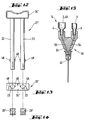
- piston rod unit 21 ' A further, currently particularly preferred embodiment of the piston rod unit 21 'can be seen from FIGS. 12 and 13, this piston rod unit 21' being intended to interact with the piston plugs 28 ', 29' shown in FIG.
- the piston rod unit 21 ' has two, for example, fully cylindrical, several mm thick piston rods 22, 23, which in turn are integrally connected to one another at their upper, outer end via a common handle part 24'.
- the plunger plugs 28 ', 29' can only be moved in the forward direction to push the components of the biological multi-component material out of the syringe unit 14, that is to say in the direction towards the syringe cones 4, 5 (see FIG. 1) , but cannot be moved back (when the piston rod unit 21 'is withdrawn, the piston rods 22, 23 move away from the piston plugs 28', 29 '). It can thus be prevented in the simplest way that the plunger plugs 28 ', 29' are inadvertently withdrawn when the syringe device 1 is used, tissue adhesive which has already been applied being sucked into the device would, which could result in clogging of the device.
- this effect could also be achieved in the embodiment according to FIGS. 7 and 8 in that the latching or snap connection 30, 31 shown there is so light that the plunger plugs 28, 29 have a firmer press fit in the syringe bodies 2, 3 as the locking heads 31 in the bores 30; this would release the locking heads 31 from the piston plugs 28, 29 when the piston rod unit 21 was withdrawn, thereby likewise preventing the piston plugs 28, 29 from being pulled back and the movement of the piston plugs 28, 29 to merely a forward movement could be limited.
- FIGS. 12 to 14 is therefore preferred over that according to FIGS. 7 and 8, since when the piston rod unit 21 'is inserted, no force has to be exerted on the piston plugs 28', 29 ', which leads to an undesired movement of the same in the direction to the syringe cones 4, 5 - which at this point are still closed with the closure cap 45 - or could lead to an increase in pressure inside the syringe bodies 2, 3. The consequence of this would be that if the closure cap were removed, 45 component material would be pressed out at the syringe cones, which would of course be undesirable and could only be avoided by pulling the plunger stopper back beforehand.
- wings or similar projections are formed in the region of the front ends of the piston rods 22, 23, as indicated at 48 in FIGS. 12 and 13. These wings 48 cause a slight press or friction fit of the piston rod unit 21 'in the syringe bodies 2, 3 when they are inserted into the respective syringe unit 14, so that the piston rod unit 21' is held sufficiently firmly in the syringe unit 14.
- the piston plugs 28 ', 29' are preferably made of silicone rubber material in order to ensure adequate sliding properties without a separate lubricant and also after long storage times (e.g. 1 to 2 years). Furthermore, this silicone material is favorable if the syringe unit is filled with a tissue adhesive, which is usually freeze-dried, since this does not impair the sliding properties of the silicone material.
- FIG. 15 the third set part of the entire syringe set, in addition to the syringe unit 14 and the piston rod unit 21 or 21 ', a dispensing part 50 in the form of a syringe body 2, 3 of a syringe unit 14 (which is only partially shown in FIG. 15) on the syringe cones 4, 5 )
- Attachable connector 51 shown which carries a mixing cannula 52 in a conventional manner and is provided with separate delivery channels or bores 53, 54 for the various components of the biological multi-component material contained in the syringe bodies 2, 3.
- Such a mixing cannula dispensing part is known, for example, from EP-A-37 393, EP-A-156 098 or EP-A-210 160;
- An alternative delivery part would also be, for example, the spray head known from EP-A-37 393 or the push-on part with closed catheter known from EP-A-156 098.
- such a delivery part 50 can be packed together with the piston rod unit 21 or 21 'in a common packaging, and separately from this the filled syringe unit 14 which is closed with the piston stopper 28, 29 or 28', 29 '(see Fig .10 and 11) packed and delivered.
- the filled and sealed with the plunger syringe unit as well as the plunger rod unit and the dispensing part must be sterile packed in separate packaging.
- syringe units with e.g. three syringe bodies arranged next to one another according to one plane are conceivable, which are connected to one another by connecting webs as described to form a fixed syringe unit.
- the described connecting webs e.g. 10, 11, be formed with reinforcing ribs, as is the stiffening web 25 of the piston rod unit 21.
- a simple, flat, vertical protective plate can of course also be provided instead of the inverted U-shaped protective part 41 or 42, which extends up to the height of the respective nozzle 43 or 44 extends and projects with the lower end into the respective receiving recess (16 in FIGS. 1 and 5) of the syringe unit 14, in order to prevent mutual contamination with the other component.
Landscapes
- Health & Medical Sciences (AREA)
- Engineering & Computer Science (AREA)
- Life Sciences & Earth Sciences (AREA)
- General Health & Medical Sciences (AREA)
- Veterinary Medicine (AREA)
- Biomedical Technology (AREA)
- Heart & Thoracic Surgery (AREA)
- Public Health (AREA)
- Animal Behavior & Ethology (AREA)
- Mechanical Engineering (AREA)
- Surgery (AREA)
- Anesthesiology (AREA)
- Vascular Medicine (AREA)
- Hematology (AREA)
- Molecular Biology (AREA)
- Medical Informatics (AREA)
- Nuclear Medicine, Radiotherapy & Molecular Imaging (AREA)
- Infusion, Injection, And Reservoir Apparatuses (AREA)
- Agricultural Chemicals And Associated Chemicals (AREA)
- Catching Or Destruction (AREA)
- Injection Moulding Of Plastics Or The Like (AREA)
- Materials For Medical Uses (AREA)
- Fertilizing (AREA)
- Nozzles (AREA)
Applications Claiming Priority (2)
| Application Number | Priority Date | Filing Date | Title |
|---|---|---|---|
| AT2085/93 | 1993-10-18 | ||
| AT0208593A AT400675B (de) | 1993-10-18 | 1993-10-18 | Spritzengarnitur zur aufbewahrung und applikation eines mehrkomponentenmaterials, spritzenvorrichtung und betätigungseinrichtung hiefür sowie verfahren zum herstellen einer befüllten, sterilen spritzenvorrichtung |
Publications (2)
| Publication Number | Publication Date |
|---|---|
| EP0648510A1 true EP0648510A1 (fr) | 1995-04-19 |
| EP0648510B1 EP0648510B1 (fr) | 1998-11-18 |
Family
ID=3527440
Family Applications (1)
| Application Number | Title | Priority Date | Filing Date |
|---|---|---|---|
| EP94890154A Expired - Lifetime EP0648510B1 (fr) | 1993-10-18 | 1994-09-26 | Dispositif de seringue pour stockage et application d'un matériau à composants multiples et procédé de fabrication |
Country Status (17)
| Country | Link |
|---|---|
| US (1) | US5464396A (fr) |
| EP (1) | EP0648510B1 (fr) |
| JP (1) | JP2837099B2 (fr) |
| AT (2) | AT400675B (fr) |
| CA (1) | CA2131875C (fr) |
| CZ (1) | CZ282039B6 (fr) |
| DE (1) | DE59407300D1 (fr) |
| DK (1) | DK0648510T3 (fr) |
| ES (1) | ES2128543T3 (fr) |
| FI (1) | FI115956B (fr) |
| HR (1) | HRP940678A2 (fr) |
| HU (1) | HU218617B (fr) |
| NO (1) | NO308511B1 (fr) |
| PL (1) | PL305479A1 (fr) |
| SI (1) | SI0648510T1 (fr) |
| SK (1) | SK126394A3 (fr) |
| YU (1) | YU60394A (fr) |
Cited By (2)
| Publication number | Priority date | Publication date | Assignee | Title |
|---|---|---|---|---|
| EP1917914A2 (fr) | 2001-02-27 | 2008-05-07 | Tyco Healthcare Group Lp | Assemblage de mélangeur extérieur |
| EP2486910A3 (fr) * | 2006-10-27 | 2012-08-22 | The Curators Of The University Of Missouri | Appareil comprenant plusieurs chambres et une tête de distribution |
Families Citing this family (99)
| Publication number | Priority date | Publication date | Assignee | Title |
|---|---|---|---|---|
| ATE244584T1 (de) * | 1995-01-16 | 2003-07-15 | Baxter Int | Selbsttragende flächengebilde aus vernetztem fibrin zur hemmung von postoperativen adhäsionen |
| US5814022A (en) * | 1996-02-06 | 1998-09-29 | Plasmaseal Llc | Method and apparatus for applying tissue sealant |
| WO2000062828A1 (fr) | 1996-04-30 | 2000-10-26 | Medtronic, Inc. | Fibrine autologue d'obturation et ses methodes de fabrication |
| DE19781869T1 (de) * | 1996-04-30 | 2000-03-16 | Medtronic Inc | Verfahren zur Herstellung eines autologen Fibrin-Blutstillungsmittels |
| AR013829A1 (es) * | 1996-07-12 | 2001-01-31 | Baxter Int | Un dispositivo medico para suministrar cantidades volumetricas de un primer y un segundo fluido, bioquimicamente reactivos, y metodo para suministrarfibrina a una superficie con dicho dispositivo |
| US5975367A (en) * | 1996-09-27 | 1999-11-02 | Thermogenesis Corp. | Fibrin glue line and dot dispenser |
| US5759171A (en) * | 1996-09-27 | 1998-06-02 | Thermogenesis Corp. | Sprayer for fibrin glue |
| US5968018A (en) * | 1996-10-30 | 1999-10-19 | Cohesion Corporation | Cell separation device and in-line orifice mixer system |
| US6783514B2 (en) | 1997-01-31 | 2004-08-31 | United States Surgical Corporation | Fibrin sealant applicator |
| DE69827132T8 (de) | 1997-07-11 | 2006-06-08 | United States Surgical Corp., Norwalk | Anordnung zur anwendung von fibrin-kleber |
| US6458095B1 (en) | 1997-10-22 | 2002-10-01 | 3M Innovative Properties Company | Dispenser for an adhesive tissue sealant having a housing with multiple cavities |
| WO1999032173A1 (fr) | 1997-12-19 | 1999-07-01 | United States Surgical Corporation | Systeme de distribution a deux elements |
| ES2362502T3 (es) | 1997-12-19 | 2011-07-06 | Tyco Healthcare Group Lp | Conjunto dispensador para una mezcla de fibrina. |
| USD408527S (en) * | 1998-02-02 | 1999-04-20 | Thermogenesis Corp. | Medical dispensing gun |
| US6039215A (en) * | 1998-06-12 | 2000-03-21 | The Procter & Gamble Company | Dual product pump dispenser with multi-outlet closure for product separation |
| US7335220B2 (en) | 2004-11-05 | 2008-02-26 | Access Closure, Inc. | Apparatus and methods for sealing a vascular puncture |
| US6471670B1 (en) | 1998-10-05 | 2002-10-29 | Karl Enrenfels | Fibrin sealant applicator system |
| DE29919291U1 (de) * | 1999-11-03 | 2000-12-21 | Dentaco Gmbh | Mehrkammer-Ampulle zum Ausgeben eines aus mehreren Substanzen bestehenden Gemisches |
| DE50009788D1 (de) | 1999-11-03 | 2005-04-21 | Dentaco Gmbh | Mehrkammer-ampulle zum ausgeben eines aus mehreren substanzen bestehenden gemisches |
| JP4647874B2 (ja) * | 2000-05-15 | 2011-03-09 | アレス トレーディング ソシエテ アノニム | 注射装置 |
| WO2002005898A1 (fr) * | 2000-07-17 | 2002-01-24 | Haemacure Corporation | Tete de pulverisation permettant d'appliquer un melange a plusieurs composants |
| US6610033B1 (en) * | 2000-10-13 | 2003-08-26 | Incept, Llc | Dual component medicinal polymer delivery system and methods of use |
| US7175336B2 (en) | 2001-01-26 | 2007-02-13 | Depuy Acromed, Inc. | Graft delivery system |
| CA2766682A1 (fr) | 2001-02-27 | 2002-09-06 | Tyco Healthcare Group Lp | Ensemble de melangeur externe |
| US6732887B2 (en) | 2002-03-26 | 2004-05-11 | Ultradent Products, Inc. | Two-part composition syringe delivery system |
| US6936033B2 (en) | 2002-06-14 | 2005-08-30 | Medtronic, Inc. | Multiple ratio fluid dispenser |
| SE519974C2 (sv) * | 2002-06-03 | 2003-05-06 | Cemvac System Ab | Anordning för utmatning av en monomer till en med en polymer förfylld blandningsanordning för tillredning av bencement |
| ES2287517T3 (es) * | 2002-09-10 | 2007-12-16 | Becton Dickinson And Company | Metodo y aparato para la administracion epidermica de una sustancia. |
| US7135027B2 (en) | 2002-10-04 | 2006-11-14 | Baxter International, Inc. | Devices and methods for mixing and extruding medically useful compositions |
| US7077339B2 (en) * | 2003-02-03 | 2006-07-18 | Biomet, Inc. | Spray applicator |
| US7331979B2 (en) * | 2003-06-04 | 2008-02-19 | Access Closure, Inc. | Apparatus and methods for sealing a vascular puncture |
| US9289195B2 (en) * | 2003-06-04 | 2016-03-22 | Access Closure, Inc. | Auto-retraction apparatus and methods for sealing a vascular puncture |
| US20050001059A1 (en) * | 2003-07-02 | 2005-01-06 | Chi-Hong Yang | Robbery control sprayer |
| US7178978B2 (en) * | 2003-09-08 | 2007-02-20 | Boston Scientific Santa Rosa Corp., | Fluid mixing apparatus and method |
| US20050067308A1 (en) * | 2003-09-30 | 2005-03-31 | Thompson Brian J. | Trocar assembly tip protector |
| US20050149117A1 (en) * | 2003-12-24 | 2005-07-07 | Farhad Khosravi | Apparatus and methods for delivering sealing materials during a percutaneous procedure to facilitate hemostasis |
| US20060116646A1 (en) * | 2004-06-28 | 2006-06-01 | Weiss Jennifer J | Bi-inoculator dual syringe clip |
| US8348971B2 (en) | 2004-08-27 | 2013-01-08 | Accessclosure, Inc. | Apparatus and methods for facilitating hemostasis within a vascular puncture |
| US8262693B2 (en) | 2004-11-05 | 2012-09-11 | Accessclosure, Inc. | Apparatus and methods for sealing a vascular puncture |
| US7611494B2 (en) | 2005-02-08 | 2009-11-03 | Confluent Surgical, Inc. | Spray for fluent materials |
| US7766900B2 (en) | 2005-02-21 | 2010-08-03 | Biomet Manufacturing Corp. | Method and apparatus for application of a fluid |
| US20060222596A1 (en) | 2005-04-01 | 2006-10-05 | Trivascular, Inc. | Non-degradable, low swelling, water soluble radiopaque hydrogel polymer |
| US7635343B2 (en) * | 2005-04-21 | 2009-12-22 | Arteriocyte Medical Systems, Inc. | Fluid dispenser |
| US8002742B2 (en) * | 2005-04-22 | 2011-08-23 | Accessclosure, Inc. | Apparatus and methods for sealing a puncture in tissue |
| US7806856B2 (en) * | 2005-04-22 | 2010-10-05 | Accessclosure, Inc. | Apparatus and method for temporary hemostasis |
| US7468049B2 (en) * | 2005-06-14 | 2008-12-23 | Rieke Corporation | Dual syringe adapter |
| US7872068B2 (en) * | 2006-05-30 | 2011-01-18 | Incept Llc | Materials formable in situ within a medical device |
| US8617204B2 (en) | 2006-09-13 | 2013-12-31 | Accessclosure, Inc. | Apparatus and methods for sealing a vascular puncture |
| US7441973B2 (en) | 2006-10-20 | 2008-10-28 | Ethicon Endo-Surgery, Inc. | Adhesive applicator |
| US7749235B2 (en) | 2006-10-20 | 2010-07-06 | Ethicon Endo-Surgery, Inc. | Stomach invagination method and apparatus |
| US7658305B2 (en) | 2006-10-25 | 2010-02-09 | Ethicon Endo-Surgery, Inc. | Adhesive applier with articulating tip |
| US8876844B2 (en) | 2006-11-01 | 2014-11-04 | Ethicon Endo-Surgery, Inc. | Anastomosis reinforcement using biosurgical adhesive and device |
| US7892250B2 (en) | 2006-11-01 | 2011-02-22 | Ethicon Endo-Surgery, Inc. | Use of biosurgical adhesive on inflatable device for gastric restriction |
| US7833216B2 (en) | 2006-11-08 | 2010-11-16 | Ethicon Endo-Surgery, Inc. | Fluid plunger adhesive dispenser |
| US20080200921A1 (en) * | 2007-02-15 | 2008-08-21 | Downer David A | Lens Delivery System |
| JP5138683B2 (ja) * | 2007-06-15 | 2013-02-06 | 一般財団法人化学及血清療法研究所 | スプレーヘッド、生体組織接着剤塗布器具、および接着剤の塗布方法 |
| US7993367B2 (en) * | 2007-09-28 | 2011-08-09 | Accessclosure, Inc. | Apparatus and methods for sealing a vascular puncture |
| WO2009059217A2 (fr) | 2007-11-02 | 2009-05-07 | Incept, Llc | Appareil et procédés de fermeture d'une perforation vasculaire |
| US7862538B2 (en) * | 2008-02-04 | 2011-01-04 | Incept Llc | Surgical delivery system for medical sealant |
| EP2254509B1 (fr) * | 2008-02-07 | 2016-01-06 | Novartis AG | Cartouche pour système d'introduction de lentille |
| US8518272B2 (en) | 2008-04-04 | 2013-08-27 | Biomet Biologics, Llc | Sterile blood separating system |
| US9364206B2 (en) | 2008-04-04 | 2016-06-14 | Access Closure, Inc. | Apparatus and methods for sealing a vascular puncture |
| US8182769B2 (en) | 2008-04-04 | 2012-05-22 | Biomet Biologics, Llc | Clean transportation system |
| US8029533B2 (en) | 2008-04-04 | 2011-10-04 | Accessclosure, Inc. | Apparatus and methods for sealing a vascular puncture |
| EP2330981B1 (fr) | 2008-08-26 | 2013-11-27 | St. Jude Medical, Inc. | Système d'obturation de perforations percutanées |
| US8801780B2 (en) | 2008-10-13 | 2014-08-12 | Alcon Research, Ltd. | Plunger tip coupling device for intraocular lens injector |
| US8308736B2 (en) | 2008-10-13 | 2012-11-13 | Alcon Research, Ltd. | Automated intraocular lens injector device |
| US8808308B2 (en) | 2008-10-13 | 2014-08-19 | Alcon Research, Ltd. | Automated intraocular lens injector device |
| EP3821817A3 (fr) * | 2008-11-12 | 2021-11-03 | Access Closure, Inc. | Appareil de fermeture d'une perforation vasculaire |
| JP5543495B2 (ja) * | 2009-02-11 | 2014-07-09 | アルコン リサーチ, リミテッド | 眼内レンズ自動注入器装置 |
| TW201039927A (en) * | 2009-03-23 | 2010-11-16 | Sulzer Mixpac Ag | Syringe for single use |
| CA2977830C (fr) * | 2009-05-04 | 2019-09-17 | Incept, Llc | Biomateriaux pour la fermeture de voie et de ponction |
| AU2010338469B2 (en) | 2009-12-17 | 2014-08-07 | Sanofi-Aventis Deutschland Gmbh | Medical device and method of assembly |
| EP2533908B1 (fr) * | 2010-02-12 | 2015-08-12 | Medmix Systems AG | Dispositif de distribution présentant un élément d'encliquetage |
| US8608642B2 (en) | 2010-02-25 | 2013-12-17 | Ethicon Endo-Surgery, Inc. | Methods and devices for treating morbid obesity using hydrogel |
| US8308799B2 (en) | 2010-04-20 | 2012-11-13 | Alcon Research, Ltd. | Modular intraocular lens injector device |
| WO2012018547A1 (fr) | 2010-07-25 | 2012-02-09 | Alcon Research, Ltd. | Dispositif automatisé d'injection de lentilles intraoculaires à double mode |
| US8961501B2 (en) | 2010-09-17 | 2015-02-24 | Incept, Llc | Method for applying flowable hydrogels to a cornea |
| EP2444336B1 (fr) * | 2010-10-21 | 2013-08-28 | Sulzer Mixpac AG | Dispositif de distribution double |
| JP5792452B2 (ja) * | 2010-11-10 | 2015-10-14 | 住友ベークライト株式会社 | 生体組織接着剤塗布用具 |
| JP6017452B2 (ja) | 2011-01-19 | 2016-11-02 | アクセスクロージャー,インク. | 血管穿刺のシーリング装置及びシーリング方法 |
| US9820728B2 (en) | 2011-01-19 | 2017-11-21 | Access Closure, Inc. | Apparatus and methods for sealing a vascular puncture |
| US9386968B2 (en) | 2011-05-11 | 2016-07-12 | Access Closure, Inc. | Apparatus and methods for sealing a vascular puncture |
| US8974436B2 (en) | 2011-10-28 | 2015-03-10 | Medtronic Xomed, Inc. | Multi-sectioned cannula with multiple lumens |
| US10441959B2 (en) | 2011-10-28 | 2019-10-15 | Medtronic Xomed, Inc. | Multi-orifice spray head |
| US9486190B2 (en) | 2011-10-28 | 2016-11-08 | Medtronic Xomed, Inc. | Spray delivery system |
| CA3078563A1 (fr) * | 2011-12-29 | 2013-07-04 | Omrix Biopharmaceuticals Ltd. | Methode et dispositif pour la dissolution rapide d'une composition proteinique solide |
| US8657835B2 (en) | 2012-01-27 | 2014-02-25 | Alcon Research, Ltd. | Automated intraocular lens injector device |
| US9757105B2 (en) | 2012-03-23 | 2017-09-12 | Accessclosure, Inc. | Apparatus and methods for sealing a vascular puncture |
| US8721680B2 (en) | 2012-03-23 | 2014-05-13 | Accessclosure, Inc. | Apparatus and methods for sealing a vascular puncture |
| US9242846B2 (en) * | 2012-04-13 | 2016-01-26 | Rooftop Research, Llc | Vee manifold |
| CN104014073B (zh) * | 2014-06-25 | 2016-10-26 | 苏州蔻美新材料有限公司 | 一种水凝液敷料注射装置 |
| US20160067406A1 (en) * | 2014-09-08 | 2016-03-10 | Ethicon, Inc. | Modular Apparatus for Delivery of Fluid Materials |
| USD791275S1 (en) * | 2015-11-02 | 2017-07-04 | Tomil S.R.O. | Dispenser for toilet cleansing |
| WO2018053565A1 (fr) * | 2016-09-22 | 2018-03-29 | St Vincent's Hospital | Appareil et procédé de biofabrication manuelle de forme libre |
| US12364818B2 (en) * | 2018-12-04 | 2025-07-22 | Solventum Intellectual Properties Company | Syringe for storing and dispensing a material |
| JP6667859B1 (ja) * | 2019-05-31 | 2020-03-18 | 株式会社Kortuc | 放射線又は抗がん化学療法増感剤投与ホルダー |
| US20220054750A1 (en) * | 2020-08-20 | 2022-02-24 | Ethicon, Inc. | Biologics delivery system and modular tip design |
| USD999599S1 (en) * | 2020-11-17 | 2023-09-26 | Lindsey Morris | Meat fluid injector |
Citations (14)
| Publication number | Priority date | Publication date | Assignee | Title |
|---|---|---|---|---|
| US3885562A (en) * | 1973-11-16 | 1975-05-27 | John C Lampkin | Syringe with writing surface |
| FR2399861A1 (fr) * | 1977-08-12 | 1979-03-09 | Viellard Paul Henri | Dispositif pour melanger puis utiliser des matieres fluides livrees a l'usager dans des emballages separes |
| US4260077A (en) * | 1979-10-04 | 1981-04-07 | Aelco Corporation | Dual separable dispenser |
| US4639250A (en) * | 1986-02-20 | 1987-01-27 | Becton, Dickinson And Company | Syringe barrel and hypodermic needle assembly |
| EP0212798A1 (fr) * | 1985-06-24 | 1987-03-04 | Joanne L. Pizzino | Seringue double |
| EP0227401A2 (fr) * | 1985-12-20 | 1987-07-01 | Mallinckrodt, Inc. (a Delaware corporation) | Méthode de production de seringues préremplies, stériles en plastic |
| US4687467A (en) * | 1986-06-11 | 1987-08-18 | C.T.F. Research Company | One-time use medical syringe invention |
| EP0255369A2 (fr) * | 1986-08-01 | 1988-02-03 | Advanced Cardiovascular Systems, Inc. | Marqueur pour la tête d'un cathéter |
| EP0294672A1 (fr) * | 1987-06-10 | 1988-12-14 | Wilhelm A. Keller | Cartouche double pour mélange à deux composants |
| US4874368A (en) * | 1988-07-25 | 1989-10-17 | Micromedics, Inc. | Fibrin glue delivery system |
| EP0425686A1 (fr) * | 1989-05-16 | 1991-05-08 | Poltavsky Meditsinsky Stomatologichesky Institut | Seringue a usage unique pour injections |
| FR2668060A1 (fr) * | 1990-10-17 | 1992-04-24 | Fondation Nale Transfusion San | Dispositif d'application d'un melange extemporane de plusieurs composants. |
| EP0485028A1 (fr) * | 1990-11-06 | 1992-05-13 | Sterling Winthrop Inc. | Support de seringue assemblable par encliquetage |
| WO1992015345A1 (fr) * | 1991-03-08 | 1992-09-17 | Habley Medical Technology Corporation | Seringue pour l'administration de produits pharmaceutiques multiples |
Family Cites Families (13)
| Publication number | Priority date | Publication date | Assignee | Title |
|---|---|---|---|---|
| US2112160A (en) * | 1933-04-04 | 1938-03-22 | Kenneth Fredericks | Method of and apparatus for effecting medicinal treatment |
| US3223083A (en) * | 1960-09-09 | 1965-12-14 | President And Directors Of Geo | Method for adhesively securing together skin and other soft tissue and bone |
| US3467096A (en) * | 1966-04-12 | 1969-09-16 | Ferrell S Horn | Multiple hypodermic syringe arrangement |
| US3828980A (en) * | 1972-11-06 | 1974-08-13 | Chem Dev Corp | Dispenser for precisely metered dispensing of viscous fluids |
| US4040420A (en) * | 1976-04-22 | 1977-08-09 | General Dynamics | Packaging and dispensing kit |
| AT366916B (de) * | 1980-04-02 | 1982-05-25 | Immuno Ag | Vorrichtung zur applikation eines gewebeklebstoffes auf basis von menschlichen oder tierischenproteinen |
| AT379311B (de) * | 1984-03-29 | 1985-12-27 | Immuno Ag | Vorrichtung zur applikation eines gewebeklebstoffes |
| AT382783B (de) * | 1985-06-20 | 1987-04-10 | Immuno Ag | Vorrichtung zur applikation eines gewebeklebstoffes |
| US4902281A (en) * | 1988-08-16 | 1990-02-20 | Corus Medical Corporation | Fibrinogen dispensing kit |
| US5116315A (en) * | 1989-10-03 | 1992-05-26 | Hemaedics, Inc. | Biological syringe system |
| FR2661097A1 (fr) * | 1990-04-23 | 1991-10-25 | Fondation Nale Transfusion San | Aiguille d'application d'une colle, notamment chirurgicale, comportant plusieurs composants melanges extemporanement. |
| US5147323A (en) * | 1991-03-08 | 1992-09-15 | Habley Medical Technology Corporation | Multiple cartridge syringe |
| US5368563A (en) * | 1991-12-18 | 1994-11-29 | Micromedics, Inc. | Sprayer assembly for physiologic glue |
-
1993
- 1993-10-18 AT AT0208593A patent/AT400675B/de not_active IP Right Cessation
-
1994
- 1994-09-12 CA CA002131875A patent/CA2131875C/fr not_active Expired - Lifetime
- 1994-09-21 HU HU9402712A patent/HU218617B/hu not_active IP Right Cessation
- 1994-09-22 US US08/310,404 patent/US5464396A/en not_active Expired - Lifetime
- 1994-09-26 ES ES94890154T patent/ES2128543T3/es not_active Expired - Lifetime
- 1994-09-26 EP EP94890154A patent/EP0648510B1/fr not_active Expired - Lifetime
- 1994-09-26 AT AT94890154T patent/ATE173408T1/de active
- 1994-09-26 DE DE59407300T patent/DE59407300D1/de not_active Expired - Lifetime
- 1994-09-26 DK DK94890154T patent/DK0648510T3/da active
- 1994-09-26 SI SI9430198T patent/SI0648510T1/xx not_active IP Right Cessation
- 1994-10-17 PL PL94305479A patent/PL305479A1/xx unknown
- 1994-10-17 CZ CZ942556A patent/CZ282039B6/cs not_active IP Right Cessation
- 1994-10-17 HR HRA2085/93A patent/HRP940678A2/xx not_active Application Discontinuation
- 1994-10-18 FI FI944894A patent/FI115956B/fi not_active IP Right Cessation
- 1994-10-18 JP JP6251837A patent/JP2837099B2/ja not_active Expired - Fee Related
- 1994-10-18 SK SK1263-94A patent/SK126394A3/sk unknown
- 1994-10-18 YU YU60394A patent/YU60394A/sh unknown
- 1994-10-18 NO NO943944A patent/NO308511B1/no not_active IP Right Cessation
Patent Citations (14)
| Publication number | Priority date | Publication date | Assignee | Title |
|---|---|---|---|---|
| US3885562A (en) * | 1973-11-16 | 1975-05-27 | John C Lampkin | Syringe with writing surface |
| FR2399861A1 (fr) * | 1977-08-12 | 1979-03-09 | Viellard Paul Henri | Dispositif pour melanger puis utiliser des matieres fluides livrees a l'usager dans des emballages separes |
| US4260077A (en) * | 1979-10-04 | 1981-04-07 | Aelco Corporation | Dual separable dispenser |
| EP0212798A1 (fr) * | 1985-06-24 | 1987-03-04 | Joanne L. Pizzino | Seringue double |
| EP0227401A2 (fr) * | 1985-12-20 | 1987-07-01 | Mallinckrodt, Inc. (a Delaware corporation) | Méthode de production de seringues préremplies, stériles en plastic |
| US4639250A (en) * | 1986-02-20 | 1987-01-27 | Becton, Dickinson And Company | Syringe barrel and hypodermic needle assembly |
| US4687467A (en) * | 1986-06-11 | 1987-08-18 | C.T.F. Research Company | One-time use medical syringe invention |
| EP0255369A2 (fr) * | 1986-08-01 | 1988-02-03 | Advanced Cardiovascular Systems, Inc. | Marqueur pour la tête d'un cathéter |
| EP0294672A1 (fr) * | 1987-06-10 | 1988-12-14 | Wilhelm A. Keller | Cartouche double pour mélange à deux composants |
| US4874368A (en) * | 1988-07-25 | 1989-10-17 | Micromedics, Inc. | Fibrin glue delivery system |
| EP0425686A1 (fr) * | 1989-05-16 | 1991-05-08 | Poltavsky Meditsinsky Stomatologichesky Institut | Seringue a usage unique pour injections |
| FR2668060A1 (fr) * | 1990-10-17 | 1992-04-24 | Fondation Nale Transfusion San | Dispositif d'application d'un melange extemporane de plusieurs composants. |
| EP0485028A1 (fr) * | 1990-11-06 | 1992-05-13 | Sterling Winthrop Inc. | Support de seringue assemblable par encliquetage |
| WO1992015345A1 (fr) * | 1991-03-08 | 1992-09-17 | Habley Medical Technology Corporation | Seringue pour l'administration de produits pharmaceutiques multiples |
Cited By (3)
| Publication number | Priority date | Publication date | Assignee | Title |
|---|---|---|---|---|
| EP1917914A2 (fr) | 2001-02-27 | 2008-05-07 | Tyco Healthcare Group Lp | Assemblage de mélangeur extérieur |
| EP1917914A3 (fr) * | 2001-02-27 | 2008-05-21 | Tyco Healthcare Group Lp | Assemblage de mélangeur extérieur |
| EP2486910A3 (fr) * | 2006-10-27 | 2012-08-22 | The Curators Of The University Of Missouri | Appareil comprenant plusieurs chambres et une tête de distribution |
Also Published As
| Publication number | Publication date |
|---|---|
| SI0648510T1 (en) | 1999-02-28 |
| NO943944L (no) | 1995-04-19 |
| CZ282039B6 (cs) | 1997-04-16 |
| US5464396A (en) | 1995-11-07 |
| HU218617B (hu) | 2000-10-28 |
| JPH07155375A (ja) | 1995-06-20 |
| DE59407300D1 (de) | 1998-12-24 |
| HUT69475A (en) | 1995-09-28 |
| CA2131875A1 (fr) | 1995-04-19 |
| FI944894A7 (fi) | 1995-04-19 |
| CZ255694A3 (en) | 1995-05-17 |
| ES2128543T3 (es) | 1999-05-16 |
| EP0648510B1 (fr) | 1998-11-18 |
| CA2131875C (fr) | 1998-11-17 |
| ATE173408T1 (de) | 1998-12-15 |
| AT400675B (de) | 1996-02-26 |
| JP2837099B2 (ja) | 1998-12-14 |
| HU9402712D0 (en) | 1995-02-28 |
| FI944894A0 (fi) | 1994-10-18 |
| DK0648510T3 (da) | 1999-08-02 |
| HRP940678A2 (en) | 1996-10-31 |
| NO308511B1 (no) | 2000-09-25 |
| YU60394A (sh) | 1997-05-28 |
| PL305479A1 (en) | 1995-05-02 |
| NO943944D0 (no) | 1994-10-18 |
| SK126394A3 (en) | 1995-07-11 |
| FI115956B (fi) | 2005-08-31 |
| ATA208593A (de) | 1995-07-15 |
Similar Documents
| Publication | Publication Date | Title |
|---|---|---|
| AT400675B (de) | Spritzengarnitur zur aufbewahrung und applikation eines mehrkomponentenmaterials, spritzenvorrichtung und betätigungseinrichtung hiefür sowie verfahren zum herstellen einer befüllten, sterilen spritzenvorrichtung | |
| DE69502357T2 (de) | Injektionsmodul für eine spritze | |
| EP2515973B1 (fr) | Dispositif d'injection comportant une gaine de protection d'aiguille | |
| DE69622949T2 (de) | Eine Arretiervorrichtung für eine Spritze | |
| DE60004082T2 (de) | Einsatzbereite verbindungsvorrichtung | |
| DE69506521T2 (de) | Automatische medikamenteneinspritzvorrichtung | |
| DE60211184T2 (de) | Bausatz und verfahren für die abgabe von gewebeklebstoff | |
| DE60037531T2 (de) | Medikamentenkartusche und injektionsvorrichtung | |
| DE69410126T2 (de) | Vorgefüllte Spritze | |
| DE69226166T2 (de) | Kunststoffspritze | |
| EP1566195B1 (fr) | Dispositif pour le stockage, le transport et l'administration d'un liquide preferablement medical | |
| CH658995A5 (de) | Zahnaerztliches allzweckabgabesystem. | |
| DE3317675A1 (de) | Zubehoerteil fuer eine injektionsvorrichtung | |
| DE10203598A1 (de) | Injektionsgerät mit steril montierter Injektionsnadel sowie Nadelträger und Ampulle für solch ein Injektionsgerät | |
| DE29824620U1 (de) | Austragvorrichtung für fließfähige Medien mittels einer Schubkolbenpumpe | |
| EP0287950A2 (fr) | Seringue de sécurite à usage unique | |
| DE2151119A1 (de) | Infusionsbesteck | |
| CH689892A5 (de) | Chirurgisches Instrument zum stossartigen Einführen einer intraossären Trokarnadel. | |
| DE10036594A1 (de) | Austragvorrichtung für Medien | |
| WO1999027986A1 (fr) | Procede et dispositif de commande de la profondeur de penetration d'une aiguille pour injection | |
| WO2007020237A1 (fr) | Contenant a deux chambres sans derivation dans le corps cylindrique | |
| DE60116409T2 (de) | Medizinische, vorgefertigte Einmalvorrichtung zum Verabreichen von mindestens zwei Medikamenten im vorgegebenen Verhältnis | |
| DE19832834A1 (de) | Sicherheits-Infusions-Katheternadel | |
| DE2259825B2 (de) | Injektionsvorrichtung | |
| DE102004020374A1 (de) | Vorrichtung zur Verabreichung eines injizierbaren Produkts mit gesicherter Dosiereinrichtung |
Legal Events
| Date | Code | Title | Description |
|---|---|---|---|
| PUAI | Public reference made under article 153(3) epc to a published international application that has entered the european phase |
Free format text: ORIGINAL CODE: 0009012 |
|
| AK | Designated contracting states |
Kind code of ref document: A1 Designated state(s): AT BE CH DE DK ES FR GB GR IE IT LI NL SE |
|
| RAX | Requested extension states of the european patent have changed |
Free format text: SI PAYMENT 941004 |
|
| 17P | Request for examination filed |
Effective date: 19950427 |
|
| 17Q | First examination report despatched |
Effective date: 19960830 |
|
| GRAG | Despatch of communication of intention to grant |
Free format text: ORIGINAL CODE: EPIDOS AGRA |
|
| GRAG | Despatch of communication of intention to grant |
Free format text: ORIGINAL CODE: EPIDOS AGRA |
|
| GRAH | Despatch of communication of intention to grant a patent |
Free format text: ORIGINAL CODE: EPIDOS IGRA |
|
| GRAH | Despatch of communication of intention to grant a patent |
Free format text: ORIGINAL CODE: EPIDOS IGRA |
|
| GRAA | (expected) grant |
Free format text: ORIGINAL CODE: 0009210 |
|
| AK | Designated contracting states |
Kind code of ref document: B1 Designated state(s): AT BE CH DE DK ES FR GB GR IE IT LI NL SE |
|
| AX | Request for extension of the european patent |
Free format text: SI PAYMENT 941004 |
|
| REF | Corresponds to: |
Ref document number: 173408 Country of ref document: AT Date of ref document: 19981215 Kind code of ref document: T |
|
| REG | Reference to a national code |
Ref country code: CH Ref legal event code: NV Representative=s name: ISLER & PEDRAZZINI AG Ref country code: CH Ref legal event code: EP |
|
| REF | Corresponds to: |
Ref document number: 59407300 Country of ref document: DE Date of ref document: 19981224 |
|
| REG | Reference to a national code |
Ref country code: IE Ref legal event code: FG4D Free format text: GERMAN |
|
| ITF | It: translation for a ep patent filed | ||
| GBT | Gb: translation of ep patent filed (gb section 77(6)(a)/1977) |
Effective date: 19990128 |
|
| ET | Fr: translation filed | ||
| REG | Reference to a national code |
Ref country code: ES Ref legal event code: FG2A Ref document number: 2128543 Country of ref document: ES Kind code of ref document: T3 |
|
| REG | Reference to a national code |
Ref country code: DK Ref legal event code: T3 |
|
| PLBE | No opposition filed within time limit |
Free format text: ORIGINAL CODE: 0009261 |
|
| STAA | Information on the status of an ep patent application or granted ep patent |
Free format text: STATUS: NO OPPOSITION FILED WITHIN TIME LIMIT |
|
| 26N | No opposition filed | ||
| REG | Reference to a national code |
Ref country code: GB Ref legal event code: IF02 |
|
| REG | Reference to a national code |
Ref country code: SI Ref legal event code: IF |
|
| REG | Reference to a national code |
Ref country code: CH Ref legal event code: PCAR Free format text: ISLER & PEDRAZZINI AG;POSTFACH 1772;8027 ZUERICH (CH) |
|
| PGFP | Annual fee paid to national office [announced via postgrant information from national office to epo] |
Ref country code: IE Payment date: 20090925 Year of fee payment: 16 Ref country code: DK Payment date: 20090925 Year of fee payment: 16 |
|
| PGFP | Annual fee paid to national office [announced via postgrant information from national office to epo] |
Ref country code: NL Payment date: 20090924 Year of fee payment: 16 |
|
| PGFP | Annual fee paid to national office [announced via postgrant information from national office to epo] |
Ref country code: GR Payment date: 20090929 Year of fee payment: 16 |
|
| PGFP | Annual fee paid to national office [announced via postgrant information from national office to epo] |
Ref country code: ES Payment date: 20100927 Year of fee payment: 17 |
|
| PGFP | Annual fee paid to national office [announced via postgrant information from national office to epo] |
Ref country code: DE Payment date: 20100929 Year of fee payment: 17 |
|
| PGFP | Annual fee paid to national office [announced via postgrant information from national office to epo] |
Ref country code: SE Payment date: 20100929 Year of fee payment: 17 Ref country code: IT Payment date: 20100928 Year of fee payment: 17 |
|
| REG | Reference to a national code |
Ref country code: NL Ref legal event code: V1 Effective date: 20110401 |
|
| REG | Reference to a national code |
Ref country code: DK Ref legal event code: EBP |
|
| REG | Reference to a national code |
Ref country code: IE Ref legal event code: MM4A |
|
| PG25 | Lapsed in a contracting state [announced via postgrant information from national office to epo] |
Ref country code: IE Free format text: LAPSE BECAUSE OF NON-PAYMENT OF DUE FEES Effective date: 20100927 Ref country code: GR Free format text: LAPSE BECAUSE OF NON-PAYMENT OF DUE FEES Effective date: 20110404 |
|
| PG25 | Lapsed in a contracting state [announced via postgrant information from national office to epo] |
Ref country code: NL Free format text: LAPSE BECAUSE OF NON-PAYMENT OF DUE FEES Effective date: 20110401 |
|
| PG25 | Lapsed in a contracting state [announced via postgrant information from national office to epo] |
Ref country code: DK Free format text: LAPSE BECAUSE OF NON-PAYMENT OF DUE FEES Effective date: 20100930 |
|
| PGFP | Annual fee paid to national office [announced via postgrant information from national office to epo] |
Ref country code: CH Payment date: 20110926 Year of fee payment: 18 |
|
| PGFP | Annual fee paid to national office [announced via postgrant information from national office to epo] |
Ref country code: AT Payment date: 20110901 Year of fee payment: 18 Ref country code: GB Payment date: 20110926 Year of fee payment: 18 Ref country code: FR Payment date: 20111005 Year of fee payment: 18 |
|
| PGFP | Annual fee paid to national office [announced via postgrant information from national office to epo] |
Ref country code: BE Payment date: 20110927 Year of fee payment: 18 |
|
| PG25 | Lapsed in a contracting state [announced via postgrant information from national office to epo] |
Ref country code: IT Free format text: LAPSE BECAUSE OF NON-PAYMENT OF DUE FEES Effective date: 20110926 |
|
| REG | Reference to a national code |
Ref country code: SE Ref legal event code: EUG |
|
| BERE | Be: lapsed |
Owner name: *IMMUNO A.G. Effective date: 20120930 |
|
| PG25 | Lapsed in a contracting state [announced via postgrant information from national office to epo] |
Ref country code: SE Free format text: LAPSE BECAUSE OF NON-PAYMENT OF DUE FEES Effective date: 20110927 |
|
| REG | Reference to a national code |
Ref country code: CH Ref legal event code: PL |
|
| REG | Reference to a national code |
Ref country code: AT Ref legal event code: MM01 Ref document number: 173408 Country of ref document: AT Kind code of ref document: T Effective date: 20120926 |
|
| GBPC | Gb: european patent ceased through non-payment of renewal fee |
Effective date: 20120926 |
|
| REG | Reference to a national code |
Ref country code: ES Ref legal event code: FD2A Effective date: 20130604 |
|
| REG | Reference to a national code |
Ref country code: FR Ref legal event code: ST Effective date: 20130531 |
|
| PG25 | Lapsed in a contracting state [announced via postgrant information from national office to epo] |
Ref country code: DE Free format text: LAPSE BECAUSE OF NON-PAYMENT OF DUE FEES Effective date: 20130403 Ref country code: LI Free format text: LAPSE BECAUSE OF NON-PAYMENT OF DUE FEES Effective date: 20120930 Ref country code: ES Free format text: LAPSE BECAUSE OF NON-PAYMENT OF DUE FEES Effective date: 20110927 Ref country code: BE Free format text: LAPSE BECAUSE OF NON-PAYMENT OF DUE FEES Effective date: 20120930 Ref country code: CH Free format text: LAPSE BECAUSE OF NON-PAYMENT OF DUE FEES Effective date: 20120930 Ref country code: GB Free format text: LAPSE BECAUSE OF NON-PAYMENT OF DUE FEES Effective date: 20120926 Ref country code: AT Free format text: LAPSE BECAUSE OF NON-PAYMENT OF DUE FEES Effective date: 20120926 |
|
| PG25 | Lapsed in a contracting state [announced via postgrant information from national office to epo] |
Ref country code: FR Free format text: LAPSE BECAUSE OF NON-PAYMENT OF DUE FEES Effective date: 20121001 |
|
| REG | Reference to a national code |
Ref country code: DE Ref legal event code: R119 Ref document number: 59407300 Country of ref document: DE Effective date: 20130403 |