EP0648621B1 - Bandage pneumatique - Google Patents
Bandage pneumatique Download PDFInfo
- Publication number
- EP0648621B1 EP0648621B1 EP19940307342 EP94307342A EP0648621B1 EP 0648621 B1 EP0648621 B1 EP 0648621B1 EP 19940307342 EP19940307342 EP 19940307342 EP 94307342 A EP94307342 A EP 94307342A EP 0648621 B1 EP0648621 B1 EP 0648621B1
- Authority
- EP
- European Patent Office
- Prior art keywords
- vibration damper
- tyre
- damper layer
- belt
- pneumatic tyre
- Prior art date
- Legal status (The legal status is an assumption and is not a legal conclusion. Google has not performed a legal analysis and makes no representation as to the accuracy of the status listed.)
- Expired - Lifetime
Links
- 239000011324 bead Substances 0.000 claims description 11
- 230000003014 reinforcing effect Effects 0.000 claims description 6
- 238000004804 winding Methods 0.000 claims description 2
- 238000005096 rolling process Methods 0.000 description 10
- 230000003247 decreasing effect Effects 0.000 description 8
- 239000000835 fiber Substances 0.000 description 6
- 239000004677 Nylon Substances 0.000 description 4
- 239000004760 aramid Substances 0.000 description 4
- 229920003235 aromatic polyamide Polymers 0.000 description 4
- 229920001778 nylon Polymers 0.000 description 4
- 230000007423 decrease Effects 0.000 description 3
- 230000000694 effects Effects 0.000 description 3
- 238000004519 manufacturing process Methods 0.000 description 3
- 239000000203 mixture Substances 0.000 description 3
- 229920000297 Rayon Polymers 0.000 description 2
- 229910000831 Steel Inorganic materials 0.000 description 2
- 238000010276 construction Methods 0.000 description 2
- 238000013016 damping Methods 0.000 description 2
- 239000000463 material Substances 0.000 description 2
- 229920000728 polyester Polymers 0.000 description 2
- 239000002964 rayon Substances 0.000 description 2
- 239000010959 steel Substances 0.000 description 2
- 238000003860 storage Methods 0.000 description 2
- 229920000742 Cotton Polymers 0.000 description 1
- 229920001875 Ebonite Polymers 0.000 description 1
- 238000005452 bending Methods 0.000 description 1
- 238000005520 cutting process Methods 0.000 description 1
- 239000000446 fuel Substances 0.000 description 1
- 238000000034 method Methods 0.000 description 1
- 238000010008 shearing Methods 0.000 description 1
- 238000010998 test method Methods 0.000 description 1
Images



Classifications
-
- B—PERFORMING OPERATIONS; TRANSPORTING
- B60—VEHICLES IN GENERAL
- B60C—VEHICLE TYRES; TYRE INFLATION; TYRE CHANGING; CONNECTING VALVES TO INFLATABLE ELASTIC BODIES IN GENERAL; DEVICES OR ARRANGEMENTS RELATED TO TYRES
- B60C9/00—Reinforcements or ply arrangement of pneumatic tyres
- B60C9/18—Structure or arrangement of belts or breakers, crown-reinforcing or cushioning layers
- B60C9/20—Structure or arrangement of belts or breakers, crown-reinforcing or cushioning layers built-up from rubberised plies each having all cords arranged substantially parallel
- B60C9/22—Structure or arrangement of belts or breakers, crown-reinforcing or cushioning layers built-up from rubberised plies each having all cords arranged substantially parallel the plies being arranged with all cords disposed along the circumference of the tyre
- B60C9/2204—Structure or arrangement of belts or breakers, crown-reinforcing or cushioning layers built-up from rubberised plies each having all cords arranged substantially parallel the plies being arranged with all cords disposed along the circumference of the tyre obtained by circumferentially narrow strip winding
-
- B—PERFORMING OPERATIONS; TRANSPORTING
- B60—VEHICLES IN GENERAL
- B60C—VEHICLE TYRES; TYRE INFLATION; TYRE CHANGING; CONNECTING VALVES TO INFLATABLE ELASTIC BODIES IN GENERAL; DEVICES OR ARRANGEMENTS RELATED TO TYRES
- B60C9/00—Reinforcements or ply arrangement of pneumatic tyres
- B60C9/18—Structure or arrangement of belts or breakers, crown-reinforcing or cushioning layers
-
- B—PERFORMING OPERATIONS; TRANSPORTING
- B60—VEHICLES IN GENERAL
- B60C—VEHICLE TYRES; TYRE INFLATION; TYRE CHANGING; CONNECTING VALVES TO INFLATABLE ELASTIC BODIES IN GENERAL; DEVICES OR ARRANGEMENTS RELATED TO TYRES
- B60C9/00—Reinforcements or ply arrangement of pneumatic tyres
- B60C9/18—Structure or arrangement of belts or breakers, crown-reinforcing or cushioning layers
- B60C9/1821—Structure or arrangement of belts or breakers, crown-reinforcing or cushioning layers comprising discrete fibres or filaments
Definitions
- the present invention relates to a pneumatic tyre with an improved belt structure capable of reducing the running noise.
- the major source of noise from a tyre is the tread configuration or pattern. Therefore, in order to reduce such noise, a great effort to improve the tread pattern has been made, and good results have been obtained.
- EP-A-0280442 discloses a pneumatic tyre comprising a breaker belt and radially outer bandage layer separated by an intermediate rubber layer.
- the intermediate rubber layer is formed in a single piece and serves to reduce the rolling resistance of the tyre and improve the breaker durability.
- an object of the present invention to provide a pneumatic tyre in which the running noise is reduced by reducing the vibration of the tread reinforcing belt, without sacrificing the running performances of the tyre.
- a pneumatic tyre comprises a carcass extending between a pair of bead portions through a tread portion and sidewall portions, a breaker belt disposed radially outside the carcass in the tread portion, a bandage belt disposed radially outside the breaker belt, and a vibration damper layer disposed between the breaker belt and the bandage belt, the vibration damper layer having a thickness of from 0.02 to 0.3 times the thickness of the tread portion measured from the tread surface at the tyre equatorial plane characterised in that the vibration damper layer is made of a plurality of axially divided pieces.
- the vibration damper layer has a loss tangent of not more than 0.15, and a complex elastic modulus (E*) of not less than 100 kgf/sq.cm.
- the vibration damper layer can not control the vibration of the breaker belt. If the thickness (t) exceeds 0.3 times the tread thickness (T), the tyre weight is increased which increases fuel consumption, and the durability of the tyre is deteriorated.
- a pneumatic tyre 1 comprises a tread 2, a pair of axially spaced bead regions 4 each with a bead core 5 therein, a pair of sidewall portions 3 extending between the tread edges and bead portions, a carcass 6 having a main portion 6a extending between the bead regions 4 through the tread 2 and the sidewall portions 3, and a pair of turned up parts 6b turned up around the bead core 5 from axially inside to the outside of the tyre, a belt disposed radially outside the carcass 6 reinforcing the tread 2, the belt comprising a breaker belt 7 disposed radially outside the carcass 6, a bandage layer 10 disposed radially outside the breaker belt 7, and a vibration damper layer 9 made of a rubber composition disposed between the breaker belt 7 and the bandage layer 10, and a bead apex 8 made of hard rubber tapering radially outwards from the bead core 5 and disposed between the carcass main portion 6a
- the carcass 6 comprises two plies 6A and 6B of organic fibre cords, e.g. nylon, polyester, rayon, aromatic polyamide or the like, arranged radially at an angle of 75 to 90 degrees with respect to the tyre equator C so that the cords of the ply 6A cross the cords of the ply 6B and so as to form a radial or semiradial carcass construction.
- the radially outer end of the turned up portions 6b extends over the radially outer end of the bead apex 8.
- the breaker belt 7 comprises two crossed plies, an inner breaker ply 7A disposed radially outside the carcass 6 adjacent to the carcass 6 and an outer breaker ply 7B disposed radially outside the inner breaker ply 7A.
- Each of the breaker belt plies 7A and 7B is made of parallel steel cords laid at an angle of from 10 to 45 degrees with respect to the tyre equator C.
- organic fibre cords e.g. nylon, polyester, rayon, aromatic polyamide or the like may be used for the breaker cords.
- the width of the inner breaker ply 7B is 0.8 to 0.95 times the tread width WT.
- the outer breaker ply 7B is slightly narrower than the inner breaker ply 7A.
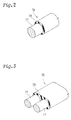
- the bandage belt 10 is formed by spirally winding a reinforcing element 16 at a small angle of from about 0 to 10 degrees with respect to the tyre equator C. As shown in Figs.2 and 3, the reinforcing element 16 is made of one or more cords, for example two cords 17 coated with a topping rubber 19. For the bandage cord, a high modulus organic fibre cord such as aromatic polyamide fibre cord or steel cord can be used.
- the bandage belt 10 has a width WD so that it substantially covers the substantially overall width of the breaker belt 7.
- the vibration damper layer 9 is disposed between the breaker belt 7 and bandage belt 10, and directly contacts both the breaker belt 7 and the bandage belt 10.
- the thickness (t) of the vibration damper layer 9 is in the range of from 0.02 to 0.30 times the tread thickness T.
- the tread thickness T is the radial distance measured from the tread face 2A to the tyre inner surface 2B at the tyre equatorial plane C.
- the width WG of the vibration damper layer 9 is not more than the maximum width WB of the breaker belt 7.
- the complex elastic modulus (E*) of the vibration damper layer 9 is not less than 100 kgf/cm 2 and more preferably also not more than 400 kgf/cm 2 .
- the loss tangent of the vibration damper layer 9 is not more than 0.15.
- the cornering force decreases. If more than 400 kgf/cm 2 , the vibration damper layer 9 is decreased in elasticity, and sometimes the damping effect can not be obtained.
- the vibration damper layer 9 is made of a rubber composition which contains short fibres uniformly mixed in its base rubber material.
- organic fibres such as nylon, aromatic polyamide, cotton fibre, or the like, having a diameter in the range of from 1 micrometers to 0.1 millimetres and a length in the range of from 20 micrometers to 2 millimetres may be used.
- nylon fibres are used.
- the complex elastic modulus (E*) of the vibration damper layer is increased in both the storage modulus (E') and loss modulus (E''). Further, the increase in the storage modulus (E') is larger than the increase in the loss modulus (E''), thereby decreasing the loss tangent or loss factor. As a result, the cornering force increases to improve the running stability. Further, as the internal energy loss of the vibration damper layer increases, the vibration energy is more effectively transformed into heat, and the vibration damping effect is increased.
- At least 90% in number of the short fibres are oriented in a certain direction within plus or minus 20 degrees.
- the above-mentioned complex elastic modulus (E*) is measured by applying a strain in the oriented direction.
- Fig.1 is an example of the vibration damper layer 9 having a one-piece structure, the width WG of which is slightly smaller than the maximum breaker belt width WB.
- At least 90% of the short fibres are oriented in the tyre circumferential direction within plus or minus 20 degrees, so that the vibration damper layer 9 is increased in tensile rigidity and compressive rigidity in the tyre circumferential direction, and the steering stability is improved. Further, the tyre production efficiency may be improved.
- the vibration damper layer 9 can be made of a plurality of pieces.
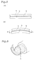
- Fig.4 shows an example of a vibration damper layer 9 which consists of three pieces: a central piece 11 centred on the tyre equator C and two lateral pieces 12 each disposed on each side thereof in an abutting relationship.
- the central piece 11 is arranged with the short fibres oriented in the tyre meridian direction
- each lateral piece 12 is arranged with the short fibres oriented in the tyre circumferential direction.
- each piece at least 90% of the short fibres are oriented in the circumferential or meridian direction within plus or minus 20 degrees as explained above.
- the width WM of the central piece 11 is in the range of from 1/3 to 1/2 times the overall width WG of the vibration damper layer 9.
- the vibration damper layer in the ground contacting patch is subjected to a bending moment (B) as shown in Fig.4, since one lateral portion is subjected to a compressive stress and the other to a tensile stress, the lateral piece 12 effectively resists its stress.
- the central piece 11 decreases the belt cord angle change and increases the cornering power as explained above. Therefore, the manoeuvrability, rolling resistance and steering stability can be improved.
- Fig.5 shows another example of the vibration damper layer 9, which has a narrow width WG of 1/4 to 1/2 times the breaker belt width WB and is disposed in only the tread central portion.
- Fig.6 shows still another example of the vibration damper layer 9, which consists of three pieces: a central piece 11 and two lateral pieces 12 similar to the example shown in Fig.4, but a space is provided between the axially adjacent pieces.
- Fig.7 shows still more another example of the vibration damper layer 9, which consists of two axially spaced lateral pieces 12, each disposed in each edge portion of the breaker belt 7.
- the normal method to manufacture the vibration damper layer is to make a rubber strip formed in the form of plain sheet by means of calendar roller or extruder.
- a rubber strip formed by cutting a rubber tube extruded in a form of tube is also possible.
- Test tyres of size 205/55R15 having the construction shown in Fig.1 were tested for the following performances.
- the rolling resistance was measured using a rolling resistance tester. The results are indicated by an index based on the Prior art tyre set at 100. The smaller the index, the smaller the rolling resistance.
- the cornering power was measured using an indoor flat belt tester. The results are indicated by an index based on the Prior art tyre being 100. The larger the index, the better the cornering power.
Landscapes
- Engineering & Computer Science (AREA)
- Mechanical Engineering (AREA)
- Tires In General (AREA)
Claims (13)
- Pneumatique comprenant une carcasse (6) disposée entre deux parties de talon (4) avec interposition d'une partie de bande de roulement (2) et de parties de flanc (3), une ceinture (7) de nappe sommet placée radialement à l'extérieur de la carcasse dans la partie de bande de roulement, une ceinture de bandage (10) disposée radialement à l'extérieur de la ceinture de nappe sommet, et une couche d'amortisseur de vibrations disposée entre la ceinture de nappe sommet et la ceinture de bandage (10), la couche (9) d'amortisseur de vibrations ayant une épaisseur (t) comprise entre 0,02 et 0,3 fois l'épaisseur (T) de la partie de bande de roulement (2), mesurée depuis la surface de la bande de roulement jusqu'à la surface interne du pneumatique au plan équatorial (C) du pneumatique, caractérisé en ce que la couche (9) d'amortisseur de vibrations est formée de plusieurs pièces divisées axialement (11, 12).
- Pneumatique selon la revendication 1, caractérisé en ce que la couche (9) d'amortisseur de vibrations contient des fibres courtes.
- Pneumatique selon la revendication 2, caractérisé en ce que 90 % au moins des fibres courtes sont orientées dans une certaine direction, et la couche (9) d'amortisseur de vibrations a une tangente à l'angle de pertes qui ne dépasse pas 0,15, et un module complexe d'élasticité qui n'est pas inférieur à 1.107 Pa (100 kgf/cm2) mesuré par application d'une contrainte dans la direction d'orientation des fibres courtes.
- Pneumatique selon la revendication 3, caractérisé en ce que le module complexe d'élasticité est inférieur à 4.107 Pa (400 kgf/cm2) lorsqu'il est mesuré par application d'une contrainte dans la direction d'orientation des fibres courtes.
- Pneumatique selon la revendication 1, 2, 3 ou 4, caractérisé en ce que la couche (9) d'amortisseur de vibrations est formée en une seule pièce ayant une largeur (WG) ne dépassant pas la largeur maximale (WB) de la ceinture de nappe sommet.
- Pneumatique selon la revendication 3, 4 ou 5, caractérisé en ce que la couche (9) d'amortisseur de vibrations est en une seule pièce, et la direction d'orientation des fibres courtes est la direction circonférentielle du pneumatique, avec une tolérance de ±20°.
- Pneumatique selon la revendication 3, 4 ou 5, caractérisé en ce que la couche (9) d'amortisseur de vibrations est en une seule pièce, et la direction d'orientation des fibres courtes est dans la direction méridienne du pneumatique, avec une tolérance de ±20°.
- Pneumatique selon la revendication 3, 4 ou 5, caractérisé en ce que la couche (9) d'amortisseur de vibrations est en une seule pièce, et la direction d'orientation des fibres courtes forme un angle de 45° avec la direction circonférentielle du pneumatique, avec une tolérance de ±20°.
- Pneumatique selon la revendication 1, 2, 3 ou 4, caractérisé en ce que la largeur totale (WG) de la couche d'amortisseur de vibrations ne dépasse pas la largeur maximale (WB) de la ceinture de nappe sommet.
- Pneumatique selon l'une quelconque des revendications 1 à 9, caractérisé en ce que la couche (9) d'amortisseur de vibrations est constituée d'une pièce centrale (11) et de deux pièces latérales (12) disposées chacune d'un côté de la pièce centrale, la pièce centrale (11) contenant des fibres courtes orientées dans la direction méridienne du pneumatique, chacune des pièces latérales (12) contenant des fibres courtes orientées dans la direction circonférentielle du pneumatique.
- Pneumatique selon la revendication 10, caractérisé en ce que la pièce centrale (11) est en butée contre les pièces latérales (12) dans la direction axiale du pneumatique, et la largeur (WM) de la pièce centrale (11) est comprise entre le tiers et la moitié de la largeur totale (WG) de la couche d'amortisseur de vibrations.
- Pneumatique selon les revendications 1 à 10, caractérisé en ce que la pièce centrale (11) est placée à distance des pièces latérales (12) dans la direction axiale du pneumatique.
- Pneumatique selon l'une quelconque des revendications précédentes, caractérisé en ce que la ceinture (7) de nappe sommet comporte deux nappes croisées, une nappe radialement interne (7A) disposée afin qu'elle soit adjacente à la carcasse (6) et une nappe radialement externe (7B) disposée radialement à l'extérieur de la nappe radialement interne (7A), chaque nappe (7A, 7B) étant formée de câblés parallèles faisant un angle compris entre 10 et 45° avec l'équateur (C) du pneumatique, et la ceinture (10) de bandage est formée par enroulement en spirale d'un élément d'armature (16) faisant un petit angle avec l'équateur (C) du pneumatique, l'élément d'armature (16) étant formé d'au moins un câblé revêtu d'un caoutchouc d'enrobage (19).
Applications Claiming Priority (2)
| Application Number | Priority Date | Filing Date | Title |
|---|---|---|---|
| JP27780293 | 1993-10-08 | ||
| JP277802/93 | 1993-10-08 |
Publications (2)
| Publication Number | Publication Date |
|---|---|
| EP0648621A1 EP0648621A1 (fr) | 1995-04-19 |
| EP0648621B1 true EP0648621B1 (fr) | 1997-12-10 |
Family
ID=17588479
Family Applications (1)
| Application Number | Title | Priority Date | Filing Date |
|---|---|---|---|
| EP19940307342 Expired - Lifetime EP0648621B1 (fr) | 1993-10-08 | 1994-10-06 | Bandage pneumatique |
Country Status (2)
| Country | Link |
|---|---|
| EP (1) | EP0648621B1 (fr) |
| DE (1) | DE69407254T2 (fr) |
Families Citing this family (2)
| Publication number | Priority date | Publication date | Assignee | Title |
|---|---|---|---|---|
| DE19528008A1 (de) * | 1995-07-31 | 1997-02-06 | Sp Reifenwerke Gmbh | Fahrzeugluftreifen |
| FR2921863B1 (fr) | 2007-10-05 | 2009-12-18 | Michelin Soc Tech | Pneumatique utilisant une structure de renfort a fibres de section aplatie |
Family Cites Families (5)
| Publication number | Priority date | Publication date | Assignee | Title |
|---|---|---|---|---|
| FR489255A (fr) * | 1961-07-06 | 1919-01-11 | Edward Bullock Webster | Dispositif mécanique propre à empecher le dérapage des automobiles et à effectuer la propulsion des bateaux, traineaux, bicyclettes, ou autres véhicules, sur la glace ou sur l'eau, ainsi qu'à d'autres usages |
| BE789075A (fr) * | 1971-09-29 | 1973-01-15 | Pirelli | Bandage pneumatique pour roue de vehicule a resistance elevee aux forces tangentielles qu'il subit au passage de trajectoires courbes |
| DE3329837A1 (de) * | 1983-08-18 | 1985-02-28 | Messerschmitt-Bölkow-Blohm GmbH, 8012 Ottobrunn | Luftreifen mit einer geraeuschmindernden daempfungseinrichtung |
| EP0280442B1 (fr) * | 1987-02-19 | 1992-04-15 | Sumitomo Rubber Industries Limited | Bandage pneumatique pour véhicules |
| IT1223508B (it) * | 1987-12-17 | 1990-09-19 | Pirelli | Struttura di cintura di pneumatici per ruote di veicoli |
-
1994
- 1994-10-06 DE DE1994607254 patent/DE69407254T2/de not_active Expired - Fee Related
- 1994-10-06 EP EP19940307342 patent/EP0648621B1/fr not_active Expired - Lifetime
Also Published As
| Publication number | Publication date |
|---|---|
| EP0648621A1 (fr) | 1995-04-19 |
| DE69407254D1 (de) | 1998-01-22 |
| DE69407254T2 (de) | 1998-04-02 |
Similar Documents
| Publication | Publication Date | Title |
|---|---|---|
| EP0595653B1 (fr) | Bandage pneumatique | |
| EP0719662B1 (fr) | Bandage pneumatique | |
| US6520232B1 (en) | Pneumatic tire with monofilament metallic belt cords | |
| EP1559588B1 (fr) | Pneu radial a couche de ceinture peripherique enroulee en spirale | |
| EP1344864B1 (fr) | Cable d'acier, procédé pour sa fabrication et pneumatique comportant un tel cable | |
| JPH08169207A (ja) | 空気入りラジアルタイヤ | |
| JP2004083001A (ja) | 空気入りラジアルタイヤ | |
| US20110120613A1 (en) | Pneumatic tire | |
| EP3581400A1 (fr) | Pneumatique | |
| EP0648621A1 (fr) | Bandage pneumatique | |
| JP2009173150A (ja) | ラジアルタイヤ | |
| WO2019116650A1 (fr) | Pneu | |
| JP3372347B2 (ja) | 空気入りラジアルタイヤ | |
| JPH04118306A (ja) | 空気入りタイヤ | |
| JP2008143347A (ja) | 空気入りタイヤ | |
| JP5558208B2 (ja) | 空気入りタイヤ | |
| JP2889283B2 (ja) | 高性能空気入りタイヤ | |
| JPH09207518A (ja) | 空気入りタイヤ | |
| JP2006213257A (ja) | 空気入りタイヤ | |
| JP2840183B2 (ja) | 空気入りタイヤ | |
| JPH0281706A (ja) | 重荷重用空気入りタイヤ | |
| JPS63173703A (ja) | 空気入りラジアルタイヤ | |
| JP2002205511A (ja) | 複合強化ゴム材および空気入りタイヤ | |
| JP7572605B2 (ja) | 空気入りタイヤ | |
| JPH08282210A (ja) | 空気入りラジアルタイヤ |
Legal Events
| Date | Code | Title | Description |
|---|---|---|---|
| PUAI | Public reference made under article 153(3) epc to a published international application that has entered the european phase |
Free format text: ORIGINAL CODE: 0009012 |
|
| AK | Designated contracting states |
Kind code of ref document: A1 Designated state(s): DE FR GB |
|
| 17P | Request for examination filed |
Effective date: 19950523 |
|
| 17Q | First examination report despatched |
Effective date: 19960422 |
|
| GRAG | Despatch of communication of intention to grant |
Free format text: ORIGINAL CODE: EPIDOS AGRA |
|
| GRAH | Despatch of communication of intention to grant a patent |
Free format text: ORIGINAL CODE: EPIDOS IGRA |
|
| GRAH | Despatch of communication of intention to grant a patent |
Free format text: ORIGINAL CODE: EPIDOS IGRA |
|
| GRAH | Despatch of communication of intention to grant a patent |
Free format text: ORIGINAL CODE: EPIDOS IGRA |
|
| GRAH | Despatch of communication of intention to grant a patent |
Free format text: ORIGINAL CODE: EPIDOS IGRA |
|
| GRAA | (expected) grant |
Free format text: ORIGINAL CODE: 0009210 |
|
| AK | Designated contracting states |
Kind code of ref document: B1 Designated state(s): DE FR GB |
|
| REF | Corresponds to: |
Ref document number: 69407254 Country of ref document: DE Date of ref document: 19980122 |
|
| ET | Fr: translation filed | ||
| PLBE | No opposition filed within time limit |
Free format text: ORIGINAL CODE: 0009261 |
|
| STAA | Information on the status of an ep patent application or granted ep patent |
Free format text: STATUS: NO OPPOSITION FILED WITHIN TIME LIMIT |
|
| 26N | No opposition filed | ||
| REG | Reference to a national code |
Ref country code: GB Ref legal event code: IF02 |
|
| PGFP | Annual fee paid to national office [announced via postgrant information from national office to epo] |
Ref country code: DE Payment date: 20071004 Year of fee payment: 14 |
|
| PGFP | Annual fee paid to national office [announced via postgrant information from national office to epo] |
Ref country code: GB Payment date: 20071003 Year of fee payment: 14 Ref country code: FR Payment date: 20071009 Year of fee payment: 14 |
|
| GBPC | Gb: european patent ceased through non-payment of renewal fee |
Effective date: 20081006 |
|
| REG | Reference to a national code |
Ref country code: FR Ref legal event code: ST Effective date: 20090630 |
|
| PG25 | Lapsed in a contracting state [announced via postgrant information from national office to epo] |
Ref country code: DE Free format text: LAPSE BECAUSE OF NON-PAYMENT OF DUE FEES Effective date: 20090501 |
|
| PG25 | Lapsed in a contracting state [announced via postgrant information from national office to epo] |
Ref country code: FR Free format text: LAPSE BECAUSE OF NON-PAYMENT OF DUE FEES Effective date: 20081031 |
|
| PG25 | Lapsed in a contracting state [announced via postgrant information from national office to epo] |
Ref country code: GB Free format text: LAPSE BECAUSE OF NON-PAYMENT OF DUE FEES Effective date: 20081006 |