EP0648657B1 - Bremskraftregler - Google Patents
Bremskraftregler Download PDFInfo
- Publication number
- EP0648657B1 EP0648657B1 EP19940115379 EP94115379A EP0648657B1 EP 0648657 B1 EP0648657 B1 EP 0648657B1 EP 19940115379 EP19940115379 EP 19940115379 EP 94115379 A EP94115379 A EP 94115379A EP 0648657 B1 EP0648657 B1 EP 0648657B1
- Authority
- EP
- European Patent Office
- Prior art keywords
- pressure
- pressure reducing
- piston
- cylinder
- hydraulic pressure
- Prior art date
- Legal status (The legal status is an assumption and is not a legal conclusion. Google has not performed a legal analysis and makes no representation as to the accuracy of the status listed.)
- Expired - Lifetime
Links
- 230000001603 reducing effect Effects 0.000 claims description 70
- 230000001105 regulatory effect Effects 0.000 claims description 4
- 238000010276 construction Methods 0.000 description 4
- 238000007789 sealing Methods 0.000 description 4
- 239000012530 fluid Substances 0.000 description 3
- 230000007246 mechanism Effects 0.000 description 3
- 230000004913 activation Effects 0.000 description 2
- 230000003247 decreasing effect Effects 0.000 description 2
- 230000009467 reduction Effects 0.000 description 2
- 230000006399 behavior Effects 0.000 description 1
- 230000007423 decrease Effects 0.000 description 1
- 238000010586 diagram Methods 0.000 description 1
- 238000003754 machining Methods 0.000 description 1
- 230000004044 response Effects 0.000 description 1
Images





Classifications
-
- B—PERFORMING OPERATIONS; TRANSPORTING
- B60—VEHICLES IN GENERAL
- B60T—VEHICLE BRAKE CONTROL SYSTEMS OR PARTS THEREOF; BRAKE CONTROL SYSTEMS OR PARTS THEREOF, IN GENERAL; ARRANGEMENT OF BRAKING ELEMENTS ON VEHICLES IN GENERAL; PORTABLE DEVICES FOR PREVENTING UNWANTED MOVEMENT OF VEHICLES; VEHICLE MODIFICATIONS TO FACILITATE COOLING OF BRAKES
- B60T8/00—Arrangements for adjusting wheel-braking force to meet varying vehicular or ground-surface conditions, e.g. limiting or varying distribution of braking force
- B60T8/26—Arrangements for adjusting wheel-braking force to meet varying vehicular or ground-surface conditions, e.g. limiting or varying distribution of braking force characterised by producing differential braking between front and rear wheels
- B60T8/261—Arrangements for adjusting wheel-braking force to meet varying vehicular or ground-surface conditions, e.g. limiting or varying distribution of braking force characterised by producing differential braking between front and rear wheels specially adapted for use in motorcycles
-
- B—PERFORMING OPERATIONS; TRANSPORTING
- B62—LAND VEHICLES FOR TRAVELLING OTHERWISE THAN ON RAILS
- B62L—BRAKES SPECIALLY ADAPTED FOR CYCLES
- B62L1/00—Brakes; Arrangements thereof
-
- B—PERFORMING OPERATIONS; TRANSPORTING
- B62—LAND VEHICLES FOR TRAVELLING OTHERWISE THAN ON RAILS
- B62L—BRAKES SPECIALLY ADAPTED FOR CYCLES
- B62L3/00—Brake-actuating mechanisms; Arrangements thereof
- B62L3/08—Mechanisms specially adapted for braking more than one wheel
Definitions
- the present invention relates to a braking force controller inserted in a line interconnecting a master cylinder and a brake cylinder to regulate an input hydraulic pressure transmitted from the master cylinder thereto and and transmits an output hydraulic pressure to the brake cylinder.
- Such a braking force controller is disclosed, for example, in Japanese Patent Publication No. 59-40672.
- the proportional pressure reducing means and the pressure reducing means are provided respectively with a proportional pressure reducing piston and a pressure reducing piston. Therefore, the conventional braking force controller needs a comparatively large number of parts and has a comparatively large size.
- EP-A-0 082 044 is a brake regulator for a vehicle in which in a regulator body there is provided a stepped cylinder bore.
- a piston is provided which is axially movable.
- One end of the piston is extending to the exterior of the regulator body and a force corresponding to the wheel load can be applied thereto.
- an axially movable separating wall member which in its central portion comprises a valve opening.
- a valve member which can be seated on the valve opening for closing same.
- the axially movable separating wall member separates an inlet and an outlet chamber from each other.
- the portion of the piston projecting into the stepped bore is provided with stepped regions for decreasing its diameter from the outer end to the end at which a valve member is provided.
- EP-A-0 451 555 discloses a braking system for a motorcycle in which a pressure control valve is disposed between a mechanical servo mechanism and a brake cylinder of a rear wheel of a motorcycle.
- the pressure control valve comprises an input port connected to the output port of the mechanical servo mechanism and an output port connected to ports of the brake cylinder of the rear wheel.
- a valve chest communicating with the input port and an oil chamber communicating with the output port are inter-connected via an oil passage, and a proportional valve is movably disposed within the valve chest.
- a cut valve is disposed in an internal chamber of the proportional valve and is biased in a closing direction by a valve spring. When the cut valve is in an opened position, the input port is in communication with the output port.
- the pressure control valve further includes a pressure reduction piston which has a leading end facing the oil chamber and a step formed at its intermediate portion.
- DE-A-30 11 138 discloses a braking force regulator for a hydraulic motorcycle brake structure.
- the brake structure comprises a rear brake and a front brake which are operable by a master cylinder respectively via a valve which is biased into an opened position.
- the respective valves are pressure reduction valves having different closing behaviours in order to ensure that upon activation of the master cylinder in a first period of time both valves are opened and that with increasing master cylinder pressure only the valve associated with the front wheel reduces the pressure and subsequently only the valve associated with the rear wheel reduces the pressure.
- a hydraulic motorcycle brake system comprising a braking force regulator.
- the braking force regulator includes a stepped piston which is displaceable against the returning force of a return spring. Further provided is a valve which is operable to close the pressure fluid connection between a pressure inlet chamber and a pressure outlet chamber of the braking force regulator.
- DE-AS 28 47 571 and DE-AS 28 47 562 disclose a braking force regulator for a hydraulic motorcycle braking system comprising a control piston which in response to activation of a master cylinder is displaceable against the force of a return spring.
- the present invention provides a braking force controller for regulating an input hydraulic pressure produced by a master cylinder and applied to an input port and transmitting a regulated hydraulic pressure through an output port to a brake cylinder, comprising: a casing provided with a cylinder communicating with the input port and the output port, a proportional pressure reducing means for reducing the rate of increase of the output hydraulic pressure according to the increase of the input hydraulic pressure, comprising a proportional pressure reducing piston slidably fitted in the cylinder so as to slide against the force of a proportional pressure reducing spring when an input hydraulic pressure acts thereon, and a cut valve held within the proportional pressure reducing piston for movement relative to the proportional pressure reducing piston to control the connection of the input port and the output port; a pressure holding means for holding the output hydraulic pressure on a fixed level regardless of increase in the input hydraulic pressure; and a pressure reducing means for reducing the output hydraulic pressure when the input hydraulic pressure increases; characterized in that the pressure reducing means comprises a pressure reducing
- the proportional pressure reducing means, the pressure holding means and the pressure reducing means are arranged coaxially within the cylinder.
- Fig. 1 is a plan view of a motorcycle incorporating a braking system.
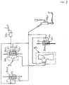
- Fig. 2 is a block diagram of the braking system.
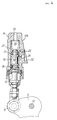
- Fig. 3 is an enlarged side view of a portion indicated at 3 in Fig. 2.
- Fig. 4 is an enlarged longitudinal sectional view of an essential portion of the arrangement shown in Fig. 3.
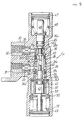
- Fig. 5 is an enlarged longitudinal sectional view of a portion indicated at 5 in Fig. 2.
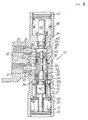
- Fig. 6 is an enlarged longitudinal sectional view, similar to Fig. 5, of assistance in explaining the operation of the braking system.
- Fig. 7 is an enlarged longitudinal sectional view, similar to Fig. 5, of assistance in explaining the operation of the braking system.
- Fig. 8 is an enlarged longitudinal sectional view, similar to Fig. 5, of assistance in explaining the operation of the braking system.
- Fig. 9 is a graph showing the braking force distribution characteristic of the braking system.
- a motorcycle V has a brake lever L held on a handlebar, and a brake pedal P supported on a main frame.
- Brake cylinders Bc FR and Bc FL are disposed on the right side and on the left side, respectively, of a front wheel Wf.
- Each of the brake cylinders Bc FR and Bc FL is provided with three pots, i.e., a front pot P 1 , a middle pot P 2 and a rear pot P 3 .
- a brake cylinder Bc R disposed near a rear wheel Wr is provided with three pots, i.e., a front pot P 1 , a middle pot P 2 and a rear pot 3 .
- a first master cylinder Mc 1 which is operated by the brake lever L, is connected directly to the front pots P 1 and the rear pots P 3 of the brake cylinders Bc FR and Bc FL for the front wheel Wf.
- a mechanical servomechanism Ms as a second master cylinder which generates a secondary braking pressure by using a braking force acting on the front wheel Wf is combined with the left brake cylinder Bc FL .
- the secondary braking pressure generated by the mechanical servomechanism Ms is transmitted through a pressure control valve Cv to the front pot P 1 and the rear pot P 3 of the brake cylinder Bc R for the rear wheel Wr.
- a second master cylinder Mc 2 which is operated by the brake pedal P, is connected to the middle pots P 2 of the brake cylinders Bc FR and Bc FL for the front wheel Wf and to the middle pot P 2 of the brake cylinder Bc R for the rear wheel Wr.
- the left brake cylinder Bc FL having a pair of brake pads disposed on the opposite sides of a brake disk 1 combined with the front wheel Wf is pivotally joined with a pin 4 to a bracket 3 fixed to a lower part of a front fork 2.
- the mechanical servomechanism Ms having a substantially cylindrical shape is held on a pair of brackets 5 at an upper part of the front fork 2 so as to extend longitudinally along the rear surface of the front fork 2.
- a substantially bar-shaped first link 7 has one end pivotally joined with a pin 8 to a bracket 6 fixed to the front fork 2.
- a substantially L-shaped second link 9 has one end pivotally joined with a pin 10 to the upper end of the brake cylinder Bc FL and the other end pivotally joined with a pin 11 to an input member 12 of the mechanical servomechanism Ms.
- the other end of the first link 7 is joined pivotally with a pin 13 to the middle of the second link 9.
- the mechanism servomechanism Ms has a casing 14 provided with a cylinder 15, and a piston 16 is fitted for axial sliding movement in the cylinder 15.
- the front end of the input member 12 is in contact with the rear end of the piston 16.
- a primary cup 17 and a secondary cup 18 are attached respectively to the front end and the rear end of the piston 16.
- a pressure chamber 20 having an outlet port 19 connected to the pressure control valve Cv is defined by the inner surface of the cylinder 15 and the primary cup 17.
- a return spring 21 for biasing the piston 16 backward is compressed in the pressure chamber 20.
- the pressure control valve Cv has a casing 30 provided with an inlet port 31 connected to the outlet port 19 of the mechanical servomechanism Ms, and an outlet port 32 connected to the front pot P 1 and the rear pot P 3 of the brake cylinder Bc R for the rear wheel Wr.
- a cylinder 34 formed in the casing 30 consists of a first cylinder 34 1 having a relatively small diameter and communicating with the outlet port 32 through a filter 35, and a second cylinder 34 2 having a relatively large diameter, communicating with the inlet port 31 through a filter 33 and coaxially joined at a shoulder 34 4 with the first cylinder 34 1 .
- a hollow outer piston 38 comprises, in an integral unit, a proportional pressure reducing piston 36 slidably fitted in the first cylinder 34 1 , and a pressure reducing piston 37 slidably fitted in the second cylinder 34 2 and coaxially joined to the proportional pressure reducing piston 36 at a shoulder 38 1 .
- the proportional pressure reducing piston 36 is provided with a sealing member 40 fitted around the proportional pressure reducing piston 36 and extending to the surface of the first cylinder 34 1 to prevent leakage.
- the pressure reducing piston 37 is provided with a sealing member 39 fitted around the pressure reducing piston 37 and extending to the surface of the second cylinder 34 2 to prevent leakage.
- the bore 38 2 of the outer piston 38 communicates with the inlet port 31 by means of a passage 38 3 , and with the outlet port 32 by means of a passage 38 4 .
- An inner piston 42 is fitted in the bore 38 2 of the outer piston 38 for sliding movement relative to the outer piston 38, and a sealing member 41 is fitted around the inner piston 42.
- a cut valve 44 is placed in the upper portion of the bore of the outer piston 38, and is biased upward by a valve spring 43 compressed between the upper end of the inner piston 42 and the cut valve 44.
- the cut valve 44 has a valve element 44 1 capable of being seated on a valve seal 38 5 formed in the inner surface of the upper wall of the outer piston 38, and a stem 44 2 extending upward from the bore 38 2 of the outer piston 38.
- a third cylinder 34 3 is formed in the upper part of the casing 30, and a cut piston 46 provided with a sealing member 45 is slidably fitted in the third cylinder 34 3 .
- the cut piston 46 is biased downward by a cut spring 48 compressed between a spring seat 47 fixed to the upper end of the casing 30 and the cut piston 46 so that the lower end thereof is in contact with the upper end of the stem 44 2 of the cut valve 44.
- the valve element 44 1 of the cut valve 44 is separated from the valve seat 38 5 of the outer piston 38 to enable the inlet port 31 to communicate with the outlet port 32 by means of the passage 38 3 , the bore 38 2 , the space around the cut valve 44 and the passage 38 4 .
- a pressure reducing spring 51 is compressed between a spring seat 49 fixed to the lower end of casing 30 supporting the inner piston 42 at its lower end, and a spring seat 50 seated on a shoulder so as to be able to move only downward.
- a predetermined space is formed between the upper surface of the spring seat 50 and the lower end of the outer piston 38.
- a proportional pressure reducing spring 53 is compressed between a spring seat 52 fitted in the casing 30 so as to be movable only downward and the upper surface of the spring seat 50.
- the spring seat 52 is pressed against a shoulder 38 6 formed in the outer piston 38.
- the preset load of the the pressure reducing spring 51 is the largest, that of the cut spring 48 is the second largest and the that of the reducing spring 53 is the smallest. Therefore, first the outer piston 38 moves down compressing the proportional pressure reducing spring 53, the cut piston 46 moves up compressing the cut spring 48, and then the outer piston 38 moves further down compressing the pressure reducing spring 51 through the spring seat 50 in contact with the lower end of the outer piston 38 as the pressure applied to the inlet port 31 increases.
- a braking pressure generated by the first master cylinder Mc 1 is transmitted to the front pots P 1 and the rear pots P 3 of the brake cylinders Bc FR and Bc FL for the front wheel Wf when the brake lever L is operated to brake the front wheel Wf.
- a braking pressure generated by the second master cylinder Mc 2 is transmitted to the middle pots P 2 of the brake cylinders Bc FR and Bc FL for the front wheel Wf and the middle pot P 2 of the brake cylinder Bc R for the rear wheel Wr to brake both the front wheel Wf and the rear wheel Wr.
- the reaction force of the brake disk 1 turns the left brake cylinder Bc FL in the direction of the arrow a on the pin 4 to push up the input member 12 through the linkage including the first link 7 and the second link 9 and, consequently, the mechanical servomechanism generates a secondary braking pressure.
- the braking force acting on the rear wheel Wr increases gradually as the breaking pressure applied to the inlet port 31 of the pressure control valve Cv increases.
- the outer piston 38 is moved downward against the preset load of the proportional pressure reducing spring 53 by the braking pressure acting on the upper surface of the outer piston 38 as shown in Fig. 6. Consequently, the valve seat 38 5 of the outer piston 38 comes into contact with the valve element 44 1 of the cut valve 44 to disconnect the inlet port 31 from the outlet port 32 temporarily.
- the braking pressure applied to the brake cylinder Bc R for the rear wheel Wr hence the braking force acting on the rear wheel Wr is varied in four steps by the agency of the pressure control valve Cv to vary the braking force distribution ratio, i.e., the ratio between the braking force acting on the front wheel Wf and the braking force acting on the rear wheel Wr, along a polygonal line O, A, B, C and D shown in Fig. 9.
- the polygonal line representing the variation of the braking force distribution ratio is in close agreement with an ideal braking force distribution curve as shown in Fig. 9.
- the braking force applied to the rear wheel Wr by the brake cylinder Bc R when the brake pedal P is operated is the sum of the braking force corresponding to the pressure applied through the pressure control valve Cv to the front pot P 1 and the rear pot P 3 of the brake cylinder Bc R by the mechanical servomechanism Ms and the braking force corresponding to the middle pot P 2 of the brake cylinder Bc R by the second master cylinder Mc 2 , which is greater than the braking force acting on the rear wheel Wr represented by the braking force distribution curve shown in Fig. 9.
- the outer piston 38 received in the cylinder formed in the casing 30 of the pressure control valve Cv and provided, in an integral unit, with the proportional pressure reducing piston 36 and the pressure reducing piston 37 is capable of both the proportional pressure reducing action and the pressure reducing action. Therefore, the pressure control valve Cv in this embodiment needs less component parts and a smaller construction than the conventional pressure control valve Cv.
- the proportional pressure reducing means i.e., the proportional pressure reducing piston
- the pressure reducing means i.e., the pressure reducing piston
- the proportional pressure reducing means, the pressure holding means and the pressure reducing means are arranged coaxially in the cylinder, which further enables the use of a relatively small casing which can be easily machined.
Landscapes
- Engineering & Computer Science (AREA)
- Mechanical Engineering (AREA)
- Transportation (AREA)
- Hydraulic Control Valves For Brake Systems (AREA)
Claims (2)
- Bremskraftregler zum Regulieren eines durch einen Geberzylinder (Ms) erzeugten und an eine Einlaßöffnung (31) angelegten Eingangshydraulikdrucks und zum Übertragen eines regulierten Hydraulikdrucks durch eine Auslaßöffnung (32) zu einem Bremszylinder (BcR), wobei der Bremskraftregler umfaßt: ein Gehäuse (30), das mit einem Zylinder (34) versehen ist, welcher mit der Einlaßöffnung (31) und der Auslaßöffnung (32) in Verbindung steht, ein Proportionaldruckverringerungsmittel zum Verringern der Zunahmerate des Ausgangshydraulikdrucks gemäß einer Zunahme des Eingangshydraulikdrucks, umfassend einen Proportionaldruckverringerungskolben (36), welcher verschiebbar in den Zylinder (30) eingepaßt ist, um sich gegen die Kraft einer Proportionaldruckverringerungsfeder (53) zu verschieben, wenn ein Eingangshydraulikdruck auf diesen einwirkt, und ein Unterbrechungsventil (44), welches innerhalb des Proportionaldruckverringerungskolbens (36) zur Bewegung bezüglich des Proportionaldruckverringerungskolben (36) gehalten ist, um die Verbindung der Einlaßöffnung (31) mit der Auslaßöffnung (32) zu steuern/regeln, ein Druckhaltemittel zum Halten des Ausgangshydraulikdrucks auf einem festen Wert unbeachtet einer Zunahme des Eingangshydraulikdrucks, und ein Druckverringerungsmittel zum Verringern des Ausgangshydraulikdrucks, wenn der Eingangshydraulikdruck zunimmt,
dadurch gekennzeichnet, daß das Druckverringerungsmittel einen Druckverringerungskolben (37) umfaßt, welcher integral mit dem Proportionaldruckverringerungskolben (36) ausgebildet ist, verschiebbar in den Zylinder (34) eingepaßt ist und sich dann, wenn der Eingangshydraulikdruck über einen vorbestimmten Wert zunimmt, gegen die vorbestimmte Last einer Druckverringerungsfeder (51) verschieben kann, welche Last größer ist als diejenige der Proportionaldruckverringerungsfeder (53). - Bremskraftregler nach Anspruch 1, worin das Proportionaldruckverringerungsmittel, das Druckhaltemittel und das Druckverringerungsmittel koaxial innerhalb des Zylinders (34) angeordnet sind.
Applications Claiming Priority (2)
| Application Number | Priority Date | Filing Date | Title |
|---|---|---|---|
| JP255361/93 | 1993-10-13 | ||
| JP05255361A JP3127337B2 (ja) | 1993-10-13 | 1993-10-13 | 制動力制御装置 |
Publications (2)
| Publication Number | Publication Date |
|---|---|
| EP0648657A1 EP0648657A1 (de) | 1995-04-19 |
| EP0648657B1 true EP0648657B1 (de) | 1997-05-28 |
Family
ID=17277715
Family Applications (1)
| Application Number | Title | Priority Date | Filing Date |
|---|---|---|---|
| EP19940115379 Expired - Lifetime EP0648657B1 (de) | 1993-10-13 | 1994-09-29 | Bremskraftregler |
Country Status (3)
| Country | Link |
|---|---|
| EP (1) | EP0648657B1 (de) |
| JP (1) | JP3127337B2 (de) |
| DE (1) | DE69403422T2 (de) |
Families Citing this family (2)
| Publication number | Priority date | Publication date | Assignee | Title |
|---|---|---|---|---|
| FR2861677B1 (fr) * | 2003-10-29 | 2006-02-10 | Beringer Sa | Dispositif limiteur de pression pour circuit hydraulique de freinage d'un vehicule |
| CN102537152B (zh) * | 2012-02-22 | 2015-05-06 | 隆鑫通用动力股份有限公司 | 联动制动系统用液压缸总成及其摩托车 |
Family Cites Families (6)
| Publication number | Priority date | Publication date | Assignee | Title |
|---|---|---|---|---|
| US4174867A (en) * | 1977-09-26 | 1979-11-20 | Itt Industries, Inc. | Brake force regulator for a motorcycle hydraulic brake system |
| DE2822933C2 (de) * | 1978-05-26 | 1984-07-26 | Alfred Teves Gmbh, 6000 Frankfurt | Bremskraftregler für ein Motorradverbund-Bremssystem |
| DE2917526C2 (de) * | 1979-04-30 | 1985-06-20 | Alfred Teves Gmbh, 6000 Frankfurt | Hydraulisches Motorrad-Bremssystem |
| DE3011138A1 (de) * | 1980-03-22 | 1981-10-01 | Alfred Teves Gmbh, 6000 Frankfurt | Bremskraftregler fuer eine hydraulische motorrad-bremsanlage |
| FR2518036B1 (fr) * | 1981-12-11 | 1987-03-20 | Marque Usine | Regulateur de freinage pour vehicule |
| EP0451555B1 (de) * | 1990-03-20 | 1995-05-31 | Honda Giken Kogyo Kabushiki Kaisha | Bremsanlage für ein Motorrad |
-
1993
- 1993-10-13 JP JP05255361A patent/JP3127337B2/ja not_active Expired - Fee Related
-
1994
- 1994-09-29 EP EP19940115379 patent/EP0648657B1/de not_active Expired - Lifetime
- 1994-09-29 DE DE1994603422 patent/DE69403422T2/de not_active Expired - Fee Related
Also Published As
| Publication number | Publication date |
|---|---|
| DE69403422D1 (de) | 1997-07-03 |
| JPH07108910A (ja) | 1995-04-25 |
| DE69403422T2 (de) | 1997-09-11 |
| JP3127337B2 (ja) | 2001-01-22 |
| EP0648657A1 (de) | 1995-04-19 |
Similar Documents
| Publication | Publication Date | Title |
|---|---|---|
| US5544946A (en) | Motorcycle braking system and method | |
| CA1090393A (en) | Two stage operation master cylinder | |
| EP0225212B1 (de) | Hydraulischer Bremskraftverstärker mit Schnellanlage und reduziertem Pedalweg | |
| US4708405A (en) | Brake pressure generator for a hydraulic brake system for use with motor vehicles | |
| JPS5940672B2 (ja) | オ−トバイ用ブレ−キシステムの減圧装置 | |
| EP0648657B1 (de) | Bremskraftregler | |
| JPH0376261B2 (de) | ||
| US4499729A (en) | Fast-fill master cylinder | |
| US4264111A (en) | Hydraulic anti-skid device | |
| EP0197803B1 (de) | Hydraulische Verstärkeranlage | |
| US4240672A (en) | Skid control system | |
| EP0221807B1 (de) | Hydraulischer Bremsverstärker mit Schnellfüllkammer und vollem Hub | |
| US5058618A (en) | Relief valve for hydraulic fluid | |
| US4852351A (en) | Dual-circuit master cylinder with solenoid opened reservoir valve | |
| JPS5848214Y2 (ja) | ブレ−キ液圧制御弁 | |
| JP3035760B2 (ja) | 自動二輪車用制動装置 | |
| EP1404555B1 (de) | Bremskraftverstärker | |
| US4377105A (en) | Hydraulic brake booster | |
| US4704867A (en) | Hydraulic brake booster with cam and lever ratio changer | |
| EP0179686B1 (de) | Hydraulische Hilfsanlage | |
| US4385547A (en) | Hydraulic brake booster | |
| JPS5953262A (ja) | ブレ−キ制御装置 | |
| US4884404A (en) | Master cylinder assembly | |
| JPS5855022B2 (ja) | 流体ブレ−キブ−スタ | |
| WO1993008058A1 (en) | Hydraulic brake booster and valve members |
Legal Events
| Date | Code | Title | Description |
|---|---|---|---|
| PUAI | Public reference made under article 153(3) epc to a published international application that has entered the european phase |
Free format text: ORIGINAL CODE: 0009012 |
|
| AK | Designated contracting states |
Kind code of ref document: A1 Designated state(s): DE FR IT |
|
| 17P | Request for examination filed |
Effective date: 19950421 |
|
| 17Q | First examination report despatched |
Effective date: 19960520 |
|
| GRAG | Despatch of communication of intention to grant |
Free format text: ORIGINAL CODE: EPIDOS AGRA |
|
| GRAH | Despatch of communication of intention to grant a patent |
Free format text: ORIGINAL CODE: EPIDOS IGRA |
|
| GRAH | Despatch of communication of intention to grant a patent |
Free format text: ORIGINAL CODE: EPIDOS IGRA |
|
| GRAA | (expected) grant |
Free format text: ORIGINAL CODE: 0009210 |
|
| AK | Designated contracting states |
Kind code of ref document: B1 Designated state(s): DE FR IT |
|
| ITF | It: translation for a ep patent filed | ||
| REF | Corresponds to: |
Ref document number: 69403422 Country of ref document: DE Date of ref document: 19970703 |
|
| ET | Fr: translation filed | ||
| PLBE | No opposition filed within time limit |
Free format text: ORIGINAL CODE: 0009261 |
|
| STAA | Information on the status of an ep patent application or granted ep patent |
Free format text: STATUS: NO OPPOSITION FILED WITHIN TIME LIMIT |
|
| 26N | No opposition filed | ||
| PGFP | Annual fee paid to national office [announced via postgrant information from national office to epo] |
Ref country code: FR Payment date: 20050823 Year of fee payment: 12 |
|
| REG | Reference to a national code |
Ref country code: FR Ref legal event code: ST Effective date: 20070531 |
|
| PGFP | Annual fee paid to national office [announced via postgrant information from national office to epo] |
Ref country code: DE Payment date: 20070927 Year of fee payment: 14 |
|
| PGFP | Annual fee paid to national office [announced via postgrant information from national office to epo] |
Ref country code: IT Payment date: 20070926 Year of fee payment: 14 |
|
| PG25 | Lapsed in a contracting state [announced via postgrant information from national office to epo] |
Ref country code: FR Free format text: LAPSE BECAUSE OF NON-PAYMENT OF DUE FEES Effective date: 20061002 |
|
| PG25 | Lapsed in a contracting state [announced via postgrant information from national office to epo] |
Ref country code: IT Free format text: LAPSE BECAUSE OF NON-PAYMENT OF DUE FEES Effective date: 20080929 Ref country code: DE Free format text: LAPSE BECAUSE OF NON-PAYMENT OF DUE FEES Effective date: 20090401 |