EP0648660A1 - Vorrichtung und Verfahren zum Antrieb und Bewegen von Schienen- oder Strassenfahrzeugen - Google Patents
Vorrichtung und Verfahren zum Antrieb und Bewegen von Schienen- oder Strassenfahrzeugen Download PDFInfo
- Publication number
- EP0648660A1 EP0648660A1 EP94402307A EP94402307A EP0648660A1 EP 0648660 A1 EP0648660 A1 EP 0648660A1 EP 94402307 A EP94402307 A EP 94402307A EP 94402307 A EP94402307 A EP 94402307A EP 0648660 A1 EP0648660 A1 EP 0648660A1
- Authority
- EP
- European Patent Office
- Prior art keywords
- rail
- frame
- propulsion
- vehicle
- pneumatic
- Prior art date
- Legal status (The legal status is an assumption and is not a legal conclusion. Google has not performed a legal analysis and makes no representation as to the accuracy of the status listed.)
- Granted
Links
Images




Classifications
-
- B—PERFORMING OPERATIONS; TRANSPORTING
- B61—RAILWAYS
- B61J—SHIFTING OR SHUNTING OF RAIL VEHICLES
- B61J3/00—Shunting or short-distance haulage devices; Similar devices for hauling trains on steep gradients or as starting aids; Car propelling devices therefor
- B61J3/12—Self-propelled tractors or pushing vehicles, e.g. mules
-
- B—PERFORMING OPERATIONS; TRANSPORTING
- B60—VEHICLES IN GENERAL
- B60F—VEHICLES FOR USE BOTH ON RAIL AND ON ROAD; VEHICLES CAPABLE OF TRAVELLING IN OR ON DIFFERENT MEDIA, e.g. AMPHIBIOUS VEHICLES
- B60F1/00—Vehicles for use both on rail and on road; Conversions therefor
- B60F1/04—Vehicles for use both on rail and on road; Conversions therefor with rail and road wheels on different axles
- B60F1/043—Vehicles comprising own propelling units
-
- B—PERFORMING OPERATIONS; TRANSPORTING
- B62—LAND VEHICLES FOR TRAVELLING OTHERWISE THAN ON RAILS
- B62D—MOTOR VEHICLES; TRAILERS
- B62D49/00—Tractors
- B62D49/005—Tractors for semi-trailers
- B62D49/007—Tractors for handling trailers, e.g. roll-trailers in terminals
Definitions
- the present invention relates to equipment making it possible to carry out the handling of railway vehicles, in general, and relates, more particularly, to a device and a method for propelling and maneuvering rail or road vehicles.
- the German company Rheiner Maschinenfabrik Windhoff AG is known for propulsion and maneuvering equipment for branch lines and railway loading stations.
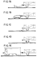
- a first propulsion equipment of the prior art consists of a vertical shaft winch on which is wound a cable used to pull one or more railway vehicles. This traction equipment with an open cable winch for maneuvering railway vehicles is shown in Figure 1a.
- a second prior art traction equipment consists of a reversible winch and a buffer trolley allowing the loading of bulk materials. Such traction equipment is shown in Figure 1b.
- a third prior art traction equipment consists of a reversible winch and a buried traction carriage in the case of buried rails. Such traction equipment is shown in Figure 1c.
- a fourth prior art traction equipment consists of a reversible winch and a traction carriage engaged on the axles of the wheels of the railway vehicle. Such traction equipment is shown in Figure 1d.
- a fifth traction equipment of the prior art consists of a railway vehicle of the type locomotive. Such traction equipment is shown in Figure 1e.
- MANUCHAR is also known for railroad vehicle storage devices.
- Figure 2 shows a rail vehicle storage device according to this state of the art.
- the rail vehicle storage device consists of a movable base carried by several drive wheels driven by drive rollers by means of chains. Guidance on the track is provided by flanged wheels.
- the rail vehicle storage device is placed on the rails by means of a forklift.
- the forklift is arranged on the base of the storage device.
- the storage device is moved by means of the forklift truck by transmission of the engine torque supplied by the carriage motor to the drive rollers via the drive wheels of the carriage.
- An object of the invention is to design a traction and maneuvering device for rail or road vehicles that is easy to insert between two vehicles and does not require the use of a traction cable, a function that cannot be obtained with traction carts. of the prior art.
- An advantage of the propulsion and maneuvering device according to the invention is its low cost, in a ratio of the order of five to ten compared to the cost of the equipment of the prior art.
- Another advantage of the propulsion and maneuvering device according to the invention is that it is flexible due to its small size, its easy use and its low weight.
- Another advantage of the propulsion and maneuvering device according to the invention is that it is non-polluting and explosion-proof.
- Another advantage of the propulsion and maneuvering device according to the invention is that it adapts to all types of bogie.
- Another advantage of the propulsion and maneuvering device according to the invention is its application in fields other than the rail sector because it adapts to any rail or road vehicle.
- Another advantage of the propulsion and maneuvering device according to the invention is its flexible and progressive starting.
- Another advantage of the propulsion and maneuvering device according to the invention is that it can be used in forward as in reverse.
- Another advantage of the propulsion and maneuvering device according to the invention is that it can be moved easily by a single operator.
- the propulsion and maneuvering device of the first preferred embodiment essentially consists of drive means 1, pressure means 5 and holding means 7.
- the drive means 1 are fixed to a frame 2 and bear on the ground 3. These drive means 1 are capable of rotating under the action of motor rotation means 4 so as to apply a longitudinal movement to the frame 2.
- the pressure means 5 are pivotally attached to the frame 2 and cooperate with a first element 6 of the rail or road vehicle so as to allow sufficient adhesion between the drive means 1 and the ground 3.
- the holding means 7 are fixed to the frame 2 and cooperate with a second element 8 of the rail or road vehicle so as to make the frame 2 integral with the rail or road vehicle.
- the drive means 1 fixed to the frame 2 consist of two drive wheels with pneumatic tires keyed at the end of an axle 9. These drive means 1 are kept free to rotate by means of a first set of three bearings 10 holding the axle 9 in rotation and integral with the framework 2.
- a first toothed wheel 11 is integral with the axle 9 and is associated with a second toothed wheel 12 driven in rotation by the motor rotation means 4.
- the gear ratio of the toothed wheels is for example 1.
- the motor rotation means 4 consist of a pneumatic motor, for example of 2.05 kW at 270 rpm, equipped with an active brake when the pressure is zero. These motor rotation means 4 are fixed to the frame 2.
- the second toothed wheel 12 is rotated by the motor rotation means 4 by means of a clutch assembly 13 with pneumatically controlled toothing and a reduction gear 14 with a cylindrical gear.
- This second toothed wheel 12 is kept free to rotate by means of a second set of two bearings 10 secured to the frame 2.
- the helical gear reducer 14 is coupled to the pneumatic motor by means of a flexible coupling 15.
- the pressure means 5 pivotally attached to the frame 2 consist of a pneumatic cylinder. This cylinder is fixed freely by one of its ends to the frame and by the other end to the first element 6 of the rail or road vehicle.
- This jack cooperates with the first element 6 of the rail or road vehicle so as to apply a directed force thereto so that the resulting force applied to the ground by the drive wheels is at best perpendicular to the plane defined by the ground.
- the force applied to the first element 6 of the rail or road vehicle is such that it allows sufficient adhesion between the drive means 1 and the ground 3.
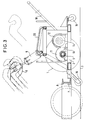
- FIG. 3 Different positions of the first element 6 of the rail or road vehicle are shown in Figure 3.
- the end of the jack fixed to the frame is secured to the frame by means of a multi-position support 20 disposed longitudinally relative to the track.
- the end of the jack can therefore be fixed on this multi-position support in different longitudinal positions so as to be able to adapt to the different positions of the first element 6 of the rail or road vehicle.
- An important technical effect is the possibility of defining a satisfactory resultant force applied to the ground by the drive wheels.
- the holding means 7, fixed to the frame 2 and cooperating with a second element 8 of the rail or road vehicle, consist of two U-shaped holding hooks. These hooks are fixed to the end of the frame in lower part.
- the first element 6 of the rail vehicle is an attachment arm of the vehicle handling bogie and the second element 8 of the rail vehicle is the cross member of this same handling bogie.
- the propulsion and maneuvering device may include guide means 16 cooperating with the rails 17 so as to guide the propulsion and maneuvering device in the rail profiles.
- the guide means 16 consist of two retractable rollers each disposed near a rail.
- the manual displacement of the propulsion and maneuvering device is effected by a telescopic drawbar 18 and a pivoting wheel 19 secured to and in the center of the frame.
- the installation of the propulsion and maneuvering device is done manually.
- the propulsion and maneuvering device being in the disengaged position, the latter is disposed on the track and brought closer to the vehicle to be moved.
- the propulsion and maneuvering device is hooked to the vehicle by tilting the device forward towards the vehicle so as to place the two holding hooks under the cross member of the handling bogie.
- the retractable guide rollers are placed near their respective rails.
- the free end of the pneumatic cylinder is fixed to the attachment arm of the vehicle handling bogie.
- the pneumatic motor, cylinder and clutch are controlled by means of a pneumatic distributor of the prior art.
- the propulsion and maneuvering device allows displacement in traction or in propulsion of the vehicle.
- Figure 6 is a front sectional view of the propulsion and maneuvering device for rail or road vehicles according to a second preferred embodiment of the invention.
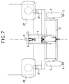
- FIG. 7 is a side view of the propulsion and maneuvering device shown in FIG. 6.
- FIG. 8 is a top view in section of the propulsion and maneuvering device shown in FIG. 6.
- the propulsion and maneuvering device of the second preferred embodiment shown in FIGS. 6 to 8 essentially consists of drive means 1, first pressure means 5 and second pressure means 21.
- the drive means 1 are fixed to a frame 2 and bear on the ground 3. These drive means 1 are capable of rotating under the action of motor rotation means 4 so as to apply a longitudinal movement to the frame 2.
- the first pressure means 5 are pivotally attached to the frame 2 and cooperate with a first element 6 of the rail or road vehicle so as to allow sufficient adhesion between the drive means 1 and the ground 3.
- the second pressure means 21 are fixed to the frame 2 and cooperate with third elements 22 of the rail or road vehicle so as to make the frame 2 integral with the rail or road vehicle.
- the first pressure means 5 pivotally attached to the frame 2 consist of a first pneumatic cylinder. This first cylinder is fixed freely by one of its ends to the frame and by the other end to the first element 6 of the rail or road vehicle.
- the second pressure means 21, fixed to the frame 2 and cooperating with third elements 22 of the rail or road vehicle, consist of a second and a third pneumatic cylinders, one end of which consists of two hooks U-shaped support.
- the second and third pneumatic cylinders are arranged on either side and in front of the first pneumatic cylinder.
- the first element 6 of the rail vehicle is an attachment arm of the vehicle handling bogie and the third elements 22 of the rail vehicle is the buffer for the absorption means 23 of the rail vehicle or road.
- the first cylinder cooperates with the first element 6 of the rail or road vehicle and the second cylinder cooperates with the third elements 22 of the rail or road vehicle.
- the first and second cylinders are associated so as to apply, respectively, to the first element 6 and to the third elements 22 of the directed forces so that the resulting force applied to the ground by the drive wheels is at best perpendicular to the plane defined by ground.
- the forces applied, respectively, to the first element 6 and to the third elements 22 of the rail or road vehicle are such that they allow sufficient adhesion between the drive means 1 and the ground 3.
- the propulsion and maneuvering device is attached to the vehicle by inserting the device under the vehicle and then placing the retaining hooks under the third elements of the rail or road vehicle.
Landscapes
- Engineering & Computer Science (AREA)
- Mechanical Engineering (AREA)
- Transportation (AREA)
- Chemical & Material Sciences (AREA)
- Combustion & Propulsion (AREA)
- Platform Screen Doors And Railroad Systems (AREA)
Applications Claiming Priority (2)
| Application Number | Priority Date | Filing Date | Title |
|---|---|---|---|
| FR9312425A FR2711344B1 (fr) | 1993-10-19 | 1993-10-19 | Dispositif et procédé de propulsion et de manÓoeuvre de véhicules ferroviaires ou routiers. |
| FR9312425 | 1993-10-19 |
Publications (2)
| Publication Number | Publication Date |
|---|---|
| EP0648660A1 true EP0648660A1 (de) | 1995-04-19 |
| EP0648660B1 EP0648660B1 (de) | 2001-04-18 |
Family
ID=9451973
Family Applications (1)
| Application Number | Title | Priority Date | Filing Date |
|---|---|---|---|
| EP19940402307 Expired - Lifetime EP0648660B1 (de) | 1993-10-19 | 1994-10-14 | Vorrichtung und Verfahren zum Antrieb und Bewegen von Schienen- oder Strassenfahrzeugen |
Country Status (3)
| Country | Link |
|---|---|
| EP (1) | EP0648660B1 (de) |
| DE (1) | DE69427110T2 (de) |
| FR (1) | FR2711344B1 (de) |
Cited By (5)
| Publication number | Priority date | Publication date | Assignee | Title |
|---|---|---|---|---|
| FR2820366A1 (fr) | 2001-02-08 | 2002-08-09 | Christian Louveau | Dispositif de guidage ferroviaire moteur et auto-directeur avec suspension hydraulique independante adaptable aux vehicules routiers |
| JP2010020934A (ja) * | 2008-07-08 | 2010-01-28 | East Japan Railway Co | 照明台車 |
| CN106428046A (zh) * | 2016-09-28 | 2017-02-22 | 上海武消汽车修理厂 | 一种轨道应急救援运载车 |
| CN108790809A (zh) * | 2018-07-27 | 2018-11-13 | 金龙联合汽车工业(苏州)有限公司 | 一种带气助力变速操纵器的安装结构 |
| CN109334364A (zh) * | 2018-09-27 | 2019-02-15 | 大连铁丰轨道交通装备有限责任公司 | 带三只行走轮的公铁两用牵引车 |
Families Citing this family (1)
| Publication number | Priority date | Publication date | Assignee | Title |
|---|---|---|---|---|
| FR2856956A1 (fr) * | 2003-07-01 | 2005-01-07 | A2C | Engin leger avec configuration rail/route et engin equipe d'un tel dispositif |
Citations (4)
| Publication number | Priority date | Publication date | Assignee | Title |
|---|---|---|---|---|
| BE671663R (de) * | 1963-02-07 | 1966-04-29 | Whiting Corp | |
| GB1136248A (en) * | 1965-12-22 | 1968-12-11 | Australian Railway Equipment | Improvements in or relating to shunting vehicles |
| BE807907A (fr) * | 1973-11-28 | 1974-03-15 | Jambes Namur Anciens Etstheoph | Pousse-wagons motorise |
| DE2312530A1 (de) * | 1973-03-10 | 1974-09-19 | Ernst Wentscher Kg Dipl Ing | Elektro-wagenschieber |
-
1993
- 1993-10-19 FR FR9312425A patent/FR2711344B1/fr not_active Expired - Fee Related
-
1994
- 1994-10-14 DE DE1994627110 patent/DE69427110T2/de not_active Expired - Fee Related
- 1994-10-14 EP EP19940402307 patent/EP0648660B1/de not_active Expired - Lifetime
Patent Citations (4)
| Publication number | Priority date | Publication date | Assignee | Title |
|---|---|---|---|---|
| BE671663R (de) * | 1963-02-07 | 1966-04-29 | Whiting Corp | |
| GB1136248A (en) * | 1965-12-22 | 1968-12-11 | Australian Railway Equipment | Improvements in or relating to shunting vehicles |
| DE2312530A1 (de) * | 1973-03-10 | 1974-09-19 | Ernst Wentscher Kg Dipl Ing | Elektro-wagenschieber |
| BE807907A (fr) * | 1973-11-28 | 1974-03-15 | Jambes Namur Anciens Etstheoph | Pousse-wagons motorise |
Cited By (6)
| Publication number | Priority date | Publication date | Assignee | Title |
|---|---|---|---|---|
| FR2820366A1 (fr) | 2001-02-08 | 2002-08-09 | Christian Louveau | Dispositif de guidage ferroviaire moteur et auto-directeur avec suspension hydraulique independante adaptable aux vehicules routiers |
| JP2010020934A (ja) * | 2008-07-08 | 2010-01-28 | East Japan Railway Co | 照明台車 |
| CN106428046A (zh) * | 2016-09-28 | 2017-02-22 | 上海武消汽车修理厂 | 一种轨道应急救援运载车 |
| CN106428046B (zh) * | 2016-09-28 | 2018-05-04 | 上海武消汽车修理厂 | 一种轨道应急救援运载车 |
| CN108790809A (zh) * | 2018-07-27 | 2018-11-13 | 金龙联合汽车工业(苏州)有限公司 | 一种带气助力变速操纵器的安装结构 |
| CN109334364A (zh) * | 2018-09-27 | 2019-02-15 | 大连铁丰轨道交通装备有限责任公司 | 带三只行走轮的公铁两用牵引车 |
Also Published As
| Publication number | Publication date |
|---|---|
| FR2711344B1 (fr) | 1995-11-17 |
| DE69427110D1 (de) | 2001-05-23 |
| EP0648660B1 (de) | 2001-04-18 |
| FR2711344A1 (fr) | 1995-04-28 |
| DE69427110T2 (de) | 2001-11-15 |
Similar Documents
| Publication | Publication Date | Title |
|---|---|---|
| EP0062370B1 (de) | Automatisches Führungssystem für ein mit Reifen ausgerüstetes Fahrzeug | |
| US20040123768A1 (en) | Rail car mover apparatus for loader vehicle | |
| FR2540447A1 (fr) | Tracteur ou vehicule analogue muni d'une prise de force decalee lateralement | |
| EP0648660B1 (de) | Vorrichtung und Verfahren zum Antrieb und Bewegen von Schienen- oder Strassenfahrzeugen | |
| CH633753A5 (fr) | Locotracteur. | |
| US5366171A (en) | Vehicle mounted reel lifting, driving and braking apparatus | |
| EP0208598B1 (de) | Schienengeführtes Fahrzeug mit Schwenkbaren Radachsen | |
| FR2759339A1 (fr) | Wagon deplacable sur des rails pour retirer des rails longs soudes de wagons de transport | |
| FR2638597A1 (fr) | Dispositif de montage d'une tete de fauchage sur un vehicule | |
| EP0675227A1 (de) | Lokal anwendbare Schleifmaschine für Eisenbahnschienen, insbesondere bei Schienenstossschweissen oder anderen lokalen Fehlern | |
| EP4043316B1 (de) | Vorrichtung zum bewegen einer auf schienen rollenden last | |
| FR2478046A1 (fr) | Installation de manutention | |
| FR2747381A1 (fr) | Dispositif de transfert d'une charge par poussee et traction dans un meme plan | |
| FR2480209A1 (fr) | Vehicule pour le transport de bois en grume | |
| FR2718082A3 (fr) | Véhicule rail-route. | |
| FR2863237A1 (fr) | Vehicule d'intervention sur des equipements ferroviaires et procede de positionnement sur des rails de ce vehicule | |
| FR2513482A1 (fr) | Dispositif pour charger du lisier dans une benne | |
| EP2176078B1 (de) | Schienen-/strassenfahrzeug für schmalspurgleise | |
| FR2729104A1 (fr) | Roue de guidage et vehicule equipe desdites roues | |
| EP0136219A1 (de) | Kombiniertes Schienenstrassenfahrzeug | |
| EP4056448B1 (de) | Bedienungsvorrichtung in einem wagen eines schienenfahrzeugs | |
| FR2526743A1 (fr) | Dispositif permettant d'immobiliser ou de faire progresser un wagon sur une voie ferree | |
| FR2540452A1 (fr) | Tracteur ou vehicule analogue a manoeuvrabilite amelioree | |
| BE666729A (de) | ||
| CA2028583A1 (fr) | Appareil de manutention et vehicule muni d'un tel appareil |
Legal Events
| Date | Code | Title | Description |
|---|---|---|---|
| PUAI | Public reference made under article 153(3) epc to a published international application that has entered the european phase |
Free format text: ORIGINAL CODE: 0009012 |
|
| AK | Designated contracting states |
Kind code of ref document: A1 Designated state(s): BE DE FR |
|
| 17P | Request for examination filed |
Effective date: 19950819 |
|
| 17Q | First examination report despatched |
Effective date: 19961011 |
|
| GRAG | Despatch of communication of intention to grant |
Free format text: ORIGINAL CODE: EPIDOS AGRA |
|
| GRAG | Despatch of communication of intention to grant |
Free format text: ORIGINAL CODE: EPIDOS AGRA |
|
| GRAH | Despatch of communication of intention to grant a patent |
Free format text: ORIGINAL CODE: EPIDOS IGRA |
|
| GRAH | Despatch of communication of intention to grant a patent |
Free format text: ORIGINAL CODE: EPIDOS IGRA |
|
| GRAA | (expected) grant |
Free format text: ORIGINAL CODE: 0009210 |
|
| AK | Designated contracting states |
Kind code of ref document: B1 Designated state(s): BE DE FR |
|
| REF | Corresponds to: |
Ref document number: 69427110 Country of ref document: DE Date of ref document: 20010523 |
|
| PLBE | No opposition filed within time limit |
Free format text: ORIGINAL CODE: 0009261 |
|
| STAA | Information on the status of an ep patent application or granted ep patent |
Free format text: STATUS: NO OPPOSITION FILED WITHIN TIME LIMIT |
|
| 26N | No opposition filed | ||
| PGFP | Annual fee paid to national office [announced via postgrant information from national office to epo] |
Ref country code: DE Payment date: 20081022 Year of fee payment: 15 |
|
| PGFP | Annual fee paid to national office [announced via postgrant information from national office to epo] |
Ref country code: BE Payment date: 20081120 Year of fee payment: 15 |
|
| PGFP | Annual fee paid to national office [announced via postgrant information from national office to epo] |
Ref country code: FR Payment date: 20081014 Year of fee payment: 15 |
|
| BERE | Be: lapsed |
Owner name: S.A. *GEC ALSTHOM TRANSPORT Effective date: 20091031 |
|
| REG | Reference to a national code |
Ref country code: FR Ref legal event code: ST Effective date: 20100630 |
|
| PG25 | Lapsed in a contracting state [announced via postgrant information from national office to epo] |
Ref country code: FR Free format text: LAPSE BECAUSE OF NON-PAYMENT OF DUE FEES Effective date: 20091102 Ref country code: DE Free format text: LAPSE BECAUSE OF NON-PAYMENT OF DUE FEES Effective date: 20100501 |
|
| PG25 | Lapsed in a contracting state [announced via postgrant information from national office to epo] |
Ref country code: BE Free format text: LAPSE BECAUSE OF NON-PAYMENT OF DUE FEES Effective date: 20091031 |