EP4056448B1 - Bedienungsvorrichtung in einem wagen eines schienenfahrzeugs - Google Patents
Bedienungsvorrichtung in einem wagen eines schienenfahrzeugs Download PDFInfo
- Publication number
- EP4056448B1 EP4056448B1 EP22160586.8A EP22160586A EP4056448B1 EP 4056448 B1 EP4056448 B1 EP 4056448B1 EP 22160586 A EP22160586 A EP 22160586A EP 4056448 B1 EP4056448 B1 EP 4056448B1
- Authority
- EP
- European Patent Office
- Prior art keywords
- roller
- motor
- bogie
- wheel
- manoeuvring device
- Prior art date
- Legal status (The legal status is an assumption and is not a legal conclusion. Google has not performed a legal analysis and makes no representation as to the accuracy of the status listed.)
- Active
Links
Images

Classifications
-
- B—PERFORMING OPERATIONS; TRANSPORTING
- B61—RAILWAYS
- B61J—SHIFTING OR SHUNTING OF RAIL VEHICLES
- B61J3/00—Shunting or short-distance haulage devices; Similar devices for hauling trains on steep gradients or as starting aids; Car propelling devices therefor
Definitions
- the present invention relates to a maneuvering device equipping a railway vehicle carriage.
- the invention aims in particular to propose a railway vehicle carriage equipped with a maneuvering device by means of which the carriage can be moved, not requiring tedious dismantling of the device when the carriage is coupled to a locomotive towing it.
- the invention relates to an operating device according to claim 1.
- the operating device is according to any one of claims 2 to 6.
- the invention also relates to a railway vehicle carriage according to claim 7 or 8.
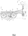
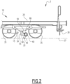
- a railway vehicle 5 comprising at least one car 10.
- Car 10 is for example a wagon of rail vehicle 5 or a locomotive of rail vehicle 5.
- the car 10 comprises at least one bogie 15, a chassis 20, a maneuvering device 25, and preferably comprises a nacelle 30.
- the bogie 15 comprises a bogie body 34 and at least one wheel 35. More particularly, the bogie 15 advantageously comprises two axles, not shown, each comprising two wheels 35. Each wheel 35 is intended to roll on a rail 37 for moving the car 10 along this rail 37.
- the bogie 15 is preferably non-motorized.
- the chassis 20 is carried by the bogie 15.
- the chassis 20 is suitable for supporting a body, not shown, within which various equipment is advantageously installed.
- the maneuvering device 25 is connected to the bogie 15 and in particular to the bogie body 34, advantageously in the same plane as one of the wheels 35 of the bogie 15. In accordance with the embodiment of the figures 1 And 2 , the maneuvering device 25 is fixed under the body 34 of the bogie 15 between the two wheels 35 included in the same plane.
- the maneuvering device 25 is connected to the chassis 20, upstream or downstream of the wheels 35.
- the concepts upstream and downstream are understood here in the sense of the movement of the car 10 on the rails 37, an upstream part of the car 10 acting as a front during the movement of the car 10.
- the operating device 25 comprises a motor 40, a roller 45, a power cable 50, a hooking system 55, an elongation system 60 and a remote control system 65.
- the nacelle 30 is integral with the chassis 20.
- the nacelle 30 is suitable for receiving an operator 67 for controlling the maneuvering device 25, and more particularly the engine 40.
- the nacelle 30 is advantageously located at the tail of the chassis 20. In other words, the nacelle 30 is advantageously located at an upstream or downstream end of the car 10.
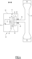
- the motor 40 comprises a casing 69 secured to the elongation device 60 described below.
- the motor 40 is an electric geared motor that can be controlled in speed.
- the motor 40 then comprises an electric machine 70 and a reducer 75.
- the engine 40 includes an electric braking system 80.
- the electric machine 70 is for example an asynchronous machine, a synchronous machine or a direct current machine.
- the electric machine 70 is for example an asynchronous machine with a power of 2.20kW operating with a voltage of 380V.
- the electric machine 70 is powered via the power cable 50 and controlled via the remote control system 65.
- the power cable 50 is connected on the one hand to an electrical energy distributor not shown and on the other hand to the electric machine 70 to provide it with the electrical energy necessary for its operation in engine mode.
- the electric machine 70 produces a rotary movement of a shaft 82 from the electrical energy coming from the power cable 50.
- the shaft 82 is connected to a reducer 75.
- the reducer 75 is intended to produce at the output a rotary movement on an axis 84 whose rotation speed is lower than the rotation speed of the shaft 82.
- the reducer 75 comprises for example a gear composed of a plurality of toothed wheels 83, meshing with each other, the axis 84 being integral with the last toothed wheel 83 of the reducer 75.
- the toothed wheels 83 are dimensioned such that an overall reduction ratio of the reducer 75 is less than 1.
- the axis 84 has a rotation speed lower than that of the shaft 82.
- the axis 84 is mounted to move relative to the casing 69 and guided in rotation by a bearing 85, for example a ball or needle bearing.
- the axis 84 is integral with the roller 45, thus allowing it to be driven in its rotation.
- the braking system 80 comprises an electromagnetic system capable of immobilizing the axis 84 when the operator 67 decides to stop the movement using equipment which will be described below.
- the roller 45 is circular in shape and has at its periphery a covering 86 made of elastic material, advantageously rubber.
- the roller 45 is movable by translation between an engaged position in which the roller 45 is in contact with the wheel 35, and a spaced position in which the roller 45 is spaced from the wheel 35. In the engaged position, the roller 45 is in contact with the wheel 35 by means of its peripheral coating 86.
- the rubber coating 86 of the roller 45 makes it possible to increase the coefficient of friction between the roller 45 and the wheel 35, and therefore to prevent slipping during rotation of the roller 45 in contact with the wheel 35.
- the elongation system 60 allowing the passage between these two positions will be described below.
- the attachment system 55 makes it possible to connect the maneuvering device 25 to the body 34 of the bogie 15.
- the attachment system 55 extends from a lower surface of the body 34 towards the rails 37.
- the attachment system 55 is for example screwed under the body 34 of the bogie 15.
- the attachment system 55 is then advantageously removable, making the maneuvering device 25 dismountable if necessary.
- a connection between the attachment system 55 and the motor 40 is made by the elongation system 60.
- the elongation system 60 comprises a first part 90 connected to the roller 45 and a second part 95 connected to the body 34 of the bogie 15.
- first part 90 is integral with the casing 69 and the second part 95 is integral with the attachment system 55.
- the elongation system 60 takes the form of a jack.
- the first part 90 takes for example the form of a piston while the second part 95 takes the form of a chamber in which the piston is able to slide.
- the first 90 and second 95 parts being movable between them.
- the first part 90 takes the form of a chamber and the second part 95 takes the form of a piston.
- the elongation system 60 is advantageously bi-stable. In other words, it comprises two stable positions, namely: an elongated position in which the elongation system 60 is as extended as possible, and a compressed position in which the elongation system 60 is as little extended as possible.
- the piston 90 in the extended position of the elongation system 60, the piston 90 is out of the chamber 95. Conversely, in the compressed position the piston 90 is substantially entirely contained in the chamber 95.
- the elongation system 60 therefore allows the roller 45 to pass from the engaged position to the separated position, and vice versa.
- the elongation system 60 is advantageously manual. In other words, the passage of the elongation system 60 from the compressed position to the extended position, and vice versa, results from a manual operation.
- the elongation system 60 is automatic.
- the transition, of the elongation system 60, from the compressed position to the extended position, and vice versa is automatic. Said transition can then, for example, be controlled from the remote control system 65.
- the remote control system 65 allows the operator 67 to control the rotation speed of the motor 40, and more particularly of the electric machine 70 via a remote control 100 and a connector 105.
- the remote control 100 allows the operator 67 and via the connector 105 to control the rotation speed of the electric machine 70 and advantageously the direction of rotation of the electric machine 70.
- the remote control 100 comprises, for example, a plurality of press buttons, rotary and/or linear potentiometers.
- connection 105 allows the communication of information from the remote control 100 to the motor 40.
- the connection 105 allows the communication of information from the remote control 100 to the electric machine 70 and to the electric braking system 80.
- the connection 105 is, in the example of the figure 1 , a 105 wired type connection.
- connection 105 is of the wireless type.
- the remote control 100 then has a wireless transmitter not shown, for example a Bluetooth transmitter, the motor 40 then has a receiver not shown, for example Bluetooth.
- the transmitter and the receiver allow the communication of information from the remote control 100 to the motor 40.
- the operator 67 actuates the elongation system 60 in order to position the roller 45 in its engaged position, against the wheel 35.
- the operator 67 then installs himself on the nacelle 30, equipped with the remote control 100.
- the operator 67 then controls the rotation speed and/or the direction of rotation of the motor 40, via its electric machine 70, from the remote control 100.
- the rotational control of the electric machine 70 induces a rotation of the shaft 82, causing a rotation of the elements of the reducer 75, leading to a rotation of the axis 84 at a rotation speed lower than that of the shaft 82.
- the axis 84 being integral of the roller 45, the roller 45 is then also rotated.
- the rotation of the roller 45 then allows the rotation of the wheel 35 by friction between the roller 45 and the wheel 35. More precisely, the rotation of the wheel 35 is due to the contact between the coating 86 and the wheel 35.
- the rotation of the wheel 35 then involves the movement of the car 10.
- the operator 67 When the operator 67 wishes to stop the car 10, he activates the electric braking system 80, for example from the remote control 100.
- the operator 67 descends from the nacelle 30 and positions the elongation system 60 in its compressed position.
- the roller 45 reaches its spread position.
- control of the elongation system 60 can be carried out from the nacelle 30.
- the maneuvering device 25 makes it possible to move the car 10 and does not necessarily have to be dismantled when the car 10 is coupled to a locomotive towing it. Indeed, the elongation system 60 makes it possible to avoid dismantling the maneuvering device 25 to move the roller 45 away from the wheel 35.
- an electric braking system 80 allows the car 10 to stop during its movement, and therefore to maneuver the car 10 with precision.
- the presence of the remote control system 65 and the nacelle 30 allows the operator 67 to control the movement of the car 10 while maintaining a view of an environment in which the operator 67 and the car 10 are moving.
- the fact that the operating device 25 is removable allows easy maintenance of its elements in the event of breakage or failure.
- the operating device 25 is connected to the chassis 20.
- the elongation system 60 is a toggle system.
- the first 90 and second 95 parts are then rods, extending respectively from the motor 40 and the attachment system 55.
- the first 90 and second 95 parts are connected by a set of connecting rods each articulating on the first part 90 or on the second part 95 on the one hand and on another connecting rod on the other hand.
- the elongation system 60 remains bistable.
- the motor 40 is directly fixed to the body 34 of the bogie 15.
- the attachment system 55 is then merged with the casing 69 of the motor 40.
- the output shaft 82 of the electric machine 70 then extends according to a upstream-downstream direction of the car 10.
- the second part 95 of the elongation system 60 is then secured to the shaft 82.
- the connection between the second part 95 and the first part 90 transmits the rotation from the shaft 82.
- the first part 90 is then no longer secured to the casing 69, but plays the role of input of the reducer 75.
- the first 90 and second 95 parts remain respectively connected to the roller 45 and to the body 34.
- the output shaft 84 of the reducer 75 remains secured to the roller 45.
- the reducer 75 then comprises toothed wheels 83 forming a gear intended to reduce the rotation speed and increase the torque at the shaft 84 and/or a device for modifying a direction of rotation around which the shaft 84 rotates, into a desired direction of rotation for the rotation of the roller 45.
- a modification device is for example a pair of bevel gears or a pair of 83 toothed wheel/worm screw.
Landscapes
- Engineering & Computer Science (AREA)
- Mechanical Engineering (AREA)
- Electric Propulsion And Braking For Vehicles (AREA)
- Platform Screen Doors And Railroad Systems (AREA)
Claims (8)
- Rangiervorrichtung (25), die geeignet ist, einen Wagen (10) eines Schienenfahrzeugs (5) auszurüsten, das ein Drehgestell (15) mit mindestens einem Rad (35) umfasst, wobei die Rangiervorrichtung (25) einen Motor (40) und eine Rolle (45) umfasst, die durch den Motor (40) in Drehung versetzt werden kann,die Rolle (45) zwischen zwei Positionen beweglich ist:- eine eingekuppelte Position, in der die Rolle (45) das Rad (35) berührt, um es durch Reibung in Drehung zu versetzen, und- eine ausgekuppelte Position, in der die Rolle (45) vom Rad (35) abgespreizt wird,wobei die Rangiervorrichtung (25) außerdem ein Verlängerungssystem (60) für den Übergang, durch Translation der Rolle (45), zwischen der ausgekuppelten und der eingekuppelten Position der Rolle (45) umfasstdas Verlängerungssystem (60) einen ersten Teil (90), der mit der Rolle (45) verbunden ist, und einen zweiten Teil (95), der geeignet ist, mit dem Drehgestell (15) verbunden zu werden, umfasst,dadurch gekennzeichnet, dass der erste (90) und zweite (95) Teilrelativ zueinander translatorisch beweglich sindfür den Übergang von der eingekuppelten zur ausgekuppelten Position der Rolle (45) und umgekehrtder Motor (40) ein Gehäuse (69) umfasst, das fest mit dem Verlängerungssystem (60) verbunden ist, wobei die Rangiervorrichtung (25) außerdem ein Einhängesystem umfasst, das geeignet ist, die Rangiervorrichtung (25) mit einem Körper (34) des Drehgestells (15) zu verbinden,wobei der erste Teil (90) fest mit dem Gehäuse (69) verbunden ist und der zweite Teil (95) fest mit dem Einhängesystem (55) verbunden ist.
- Rangiervorrichtung (25) nach Anspruch 1, dadurch gekennzeichnet, dass die Rolle (45) an ihrem Umfang eine Beschichtung (86) aus Gummi aufweist.
- Rangiervorrichtung (25) nach Anspruch 1 oder 2, dadurch gekennzeichnet, dass der Motor (40) ein elektrischer Getriebemotor ist.
- Rangiervorrichtung (25) nach einem der vorhergehenden Ansprüche, dadurch gekennzeichnet, dass der Motor (40) ein elektrisches Bremssystem (80) umfasst.
- Rangiervorrichtung (25) nach einem der vorhergehenden Ansprüche, dadurch gekennzeichnet, dass die Rangiervorrichtung (25) ein System zur Fernsteuerung (65) einer Drehgeschwindigkeit des Motors (40) umfasst.
- Rangiervorrichtung (25) nach einem der vorhergehenden Ansprüche, wobei das Verlängerungssystem (60) ein Zylinder ist,
wobei entweder der erste (90) Teil oder der zweite (95) Teil eine Kammer ist, wobei der andere ein Kolben ist, der dazu bestimmt ist, innerhalb der Kammer zu gleiten. - Wagen (10) eines Schienenfahrzeugs (5) mit einem Drehgestell (15), das mindestens ein Rad (35) aufweist, dadurch gekennzeichnet, dass der Wagen mit einer Rangiervorrichtung nach einem der vorhergehenden Ansprüche ausgestattet ist.
- Wagen (10) eines Schienenfahrzeugs (5) nach dem vorhergehenden Anspruch, mit einem vom Drehgestell (15) getragenen Chassis (20) und einer Gondel (30), die mit dem Chassis (20) fest verbunden ist und einen Bediener (67) zur Steuerung des Motors (40) aufnehmen kann.
Applications Claiming Priority (1)
| Application Number | Priority Date | Filing Date | Title |
|---|---|---|---|
| FR2102196A FR3120341B1 (fr) | 2021-03-08 | 2021-03-08 | Dispositif de manœuvre équipant une voiture de véhicule ferroviaire |
Publications (2)
| Publication Number | Publication Date |
|---|---|
| EP4056448A1 EP4056448A1 (de) | 2022-09-14 |
| EP4056448B1 true EP4056448B1 (de) | 2025-02-12 |
Family
ID=76730635
Family Applications (1)
| Application Number | Title | Priority Date | Filing Date |
|---|---|---|---|
| EP22160586.8A Active EP4056448B1 (de) | 2021-03-08 | 2022-03-07 | Bedienungsvorrichtung in einem wagen eines schienenfahrzeugs |
Country Status (2)
| Country | Link |
|---|---|
| EP (1) | EP4056448B1 (de) |
| FR (1) | FR3120341B1 (de) |
Family Cites Families (6)
| Publication number | Priority date | Publication date | Assignee | Title |
|---|---|---|---|---|
| US398207A (en) * | 1889-02-19 | Mechanism for oars | ||
| NL16490C (de) * | 1924-10-07 | |||
| US2989007A (en) | 1958-10-28 | 1961-06-20 | Movet Ind Inc | Railway car mover |
| US3785297A (en) * | 1971-07-26 | 1974-01-15 | Maxson Corp | Motorized railway scale test car |
| FR2691422B1 (fr) * | 1992-05-19 | 1994-08-26 | Abrf | Dispositif de motorisation embarqué pour wagon à essieux ou à bogies munis d'essieux. |
| SE511281C2 (sv) * | 1998-09-14 | 1999-09-06 | Jan Staffan Aasander | Motordrivet arrangemang för förflyttning av järnvägsfordon |
-
2021
- 2021-03-08 FR FR2102196A patent/FR3120341B1/fr active Active
-
2022
- 2022-03-07 EP EP22160586.8A patent/EP4056448B1/de active Active
Also Published As
| Publication number | Publication date |
|---|---|
| FR3120341A1 (fr) | 2022-09-09 |
| EP4056448A1 (de) | 2022-09-14 |
| FR3120341B1 (fr) | 2025-05-02 |
Similar Documents
| Publication | Publication Date | Title |
|---|---|---|
| EP2537751B1 (de) | Radmotorisierungssystem für eine radaufhängung | |
| EP2543592B1 (de) | Elektrisches Motorisierungssystem eines Rads | |
| EP1845016B1 (de) | Fahrwerk umfassend mehrere elektromechanische Ausrichtungsstellglieder | |
| EP2123590B1 (de) | Steuerverfahren der Richtungsbewegung des Drehteils eines Turmkrans | |
| FR2988797A1 (fr) | Actionneur electromecanique de surface de vol d'aeronef et aeronef pourvu d'un tel actionneur | |
| FR2546454A1 (fr) | Vehicule de travail autopropulse | |
| EP4056448B1 (de) | Bedienungsvorrichtung in einem wagen eines schienenfahrzeugs | |
| EP2909066B1 (de) | Getriebeanordnung für eine selbstfahrende maschine zur positionierung zwischen der hauptmotorwelle und den rädern dieser maschine | |
| BE1008762A6 (fr) | Appareil de levage et de manoeuvre d'un vehicule automobile et vehicule autmobile equipe d'un tel dispositif. | |
| EP2127917B1 (de) | Fahrgestell mit elektrischer Federung, das mit einem Reduzierstück ausgestattet ist, und seine Anwendung | |
| WO2015082090A1 (fr) | Actionneur electrique a moyens manuels d'entrainement | |
| FR2658475A1 (fr) | Vehicule a cabine elevatrice. | |
| FR3038678A1 (fr) | Actionneur de frein a double demultiplication, etrier et frein, et procede d'actionnement | |
| EP2127918B1 (de) | Fahrzeug mit elektrischem Antrieb und zwei Achsen | |
| FR2807977A1 (fr) | Systeme d'actionnement d'une timonerie de commande d'un equipage mobile dans un dispositif d'accouplement pilote, tel qu'un embrayage par exemple | |
| FR2587424A1 (fr) | Joint d'accouplement temporaire entre un arbre moteur et un arbre recepteur, en particulier pour l'entrainement de chariot motorises de transport aerien | |
| EP0112735A1 (de) | Hilfsapparat für Anhängerhandantrieb, insbesondere für Wohnwagen | |
| EP1093985A1 (de) | Feststellbremsvorrichtung für ein Kraftfahrzeug mit Automatikgetriebe und Kraftfahrzeug mit einer solchen Vorrichtung | |
| EP0384871A1 (de) | Handbetätigtes Steuersystem des Einstellwinkels einer Flugzeugluftschraube | |
| FR2761089A1 (fr) | Dispositif de signalisation temporaire pour chantier mobile | |
| BE886694A (fr) | Procede et dispositif de transformation de l'energie eolienne | |
| FR2609517A1 (fr) | Dispositif d'entrainement simultane des vis de deux systemes vis-ecrou paralleles | |
| EP0338167A1 (de) | Antriebsvorrichtung für zwei simultan anzutreibende, parallele Schraubgetriebe | |
| FR2703303A1 (fr) | Dispositif de commande d'un volet pivotant procurant une position stable. | |
| CH396658A (fr) | Dispositif pour soulever et déplacer latéralement un véhicule |
Legal Events
| Date | Code | Title | Description |
|---|---|---|---|
| PUAI | Public reference made under article 153(3) epc to a published international application that has entered the european phase |
Free format text: ORIGINAL CODE: 0009012 |
|
| STAA | Information on the status of an ep patent application or granted ep patent |
Free format text: STATUS: THE APPLICATION HAS BEEN PUBLISHED |
|
| STAA | Information on the status of an ep patent application or granted ep patent |
Free format text: STATUS: REQUEST FOR EXAMINATION WAS MADE |
|
| AK | Designated contracting states |
Kind code of ref document: A1 Designated state(s): AL AT BE BG CH CY CZ DE DK EE ES FI FR GB GR HR HU IE IS IT LI LT LU LV MC MK MT NL NO PL PT RO RS SE SI SK SM TR |
|
| 17P | Request for examination filed |
Effective date: 20220819 |
|
| RBV | Designated contracting states (corrected) |
Designated state(s): AL AT BE BG CH CY CZ DE DK EE ES FI FR GB GR HR HU IE IS IT LI LT LU LV MC MK MT NL NO PL PT RO RS SE SI SK SM TR |
|
| P01 | Opt-out of the competence of the unified patent court (upc) registered |
Effective date: 20230823 |
|
| GRAP | Despatch of communication of intention to grant a patent |
Free format text: ORIGINAL CODE: EPIDOSNIGR1 |
|
| STAA | Information on the status of an ep patent application or granted ep patent |
Free format text: STATUS: GRANT OF PATENT IS INTENDED |
|
| INTG | Intention to grant announced |
Effective date: 20240910 |
|
| GRAF | Information related to payment of grant fee modified |
Free format text: ORIGINAL CODE: EPIDOSCIGR3 |
|
| GRAS | Grant fee paid |
Free format text: ORIGINAL CODE: EPIDOSNIGR3 |
|
| GRAA | (expected) grant |
Free format text: ORIGINAL CODE: 0009210 |
|
| STAA | Information on the status of an ep patent application or granted ep patent |
Free format text: STATUS: THE PATENT HAS BEEN GRANTED |
|
| RIN1 | Information on inventor provided before grant (corrected) |
Inventor name: CHIARANDINI, BRUNO Inventor name: HAVET, JEAN-LUC |
|
| AK | Designated contracting states |
Kind code of ref document: B1 Designated state(s): AL AT BE BG CH CY CZ DE DK EE ES FI FR GB GR HR HU IE IS IT LI LT LU LV MC MK MT NL NO PL PT RO RS SE SI SK SM TR |
|
| REG | Reference to a national code |
Ref country code: GB Ref legal event code: FG4D Free format text: NOT ENGLISH |
|
| REG | Reference to a national code |
Ref country code: CH Ref legal event code: EP |
|
| REG | Reference to a national code |
Ref country code: DE Ref legal event code: R096 Ref document number: 602022010345 Country of ref document: DE |
|
| REG | Reference to a national code |
Ref country code: IE Ref legal event code: FG4D Free format text: LANGUAGE OF EP DOCUMENT: FRENCH |
|
| PGFP | Annual fee paid to national office [announced via postgrant information from national office to epo] |
Ref country code: AT Payment date: 20250417 Year of fee payment: 4 |
|
| REG | Reference to a national code |
Ref country code: NL Ref legal event code: MP Effective date: 20250212 |
|
| PG25 | Lapsed in a contracting state [announced via postgrant information from national office to epo] |
Ref country code: RS Free format text: LAPSE BECAUSE OF FAILURE TO SUBMIT A TRANSLATION OF THE DESCRIPTION OR TO PAY THE FEE WITHIN THE PRESCRIBED TIME-LIMIT Effective date: 20250512 |
|
| PG25 | Lapsed in a contracting state [announced via postgrant information from national office to epo] |
Ref country code: FI Free format text: LAPSE BECAUSE OF FAILURE TO SUBMIT A TRANSLATION OF THE DESCRIPTION OR TO PAY THE FEE WITHIN THE PRESCRIBED TIME-LIMIT Effective date: 20250212 |
|
| PG25 | Lapsed in a contracting state [announced via postgrant information from national office to epo] |
Ref country code: PL Free format text: LAPSE BECAUSE OF FAILURE TO SUBMIT A TRANSLATION OF THE DESCRIPTION OR TO PAY THE FEE WITHIN THE PRESCRIBED TIME-LIMIT Effective date: 20250212 |
|
| PG25 | Lapsed in a contracting state [announced via postgrant information from national office to epo] |
Ref country code: ES Free format text: LAPSE BECAUSE OF FAILURE TO SUBMIT A TRANSLATION OF THE DESCRIPTION OR TO PAY THE FEE WITHIN THE PRESCRIBED TIME-LIMIT Effective date: 20250212 |
|
| REG | Reference to a national code |
Ref country code: LT Ref legal event code: MG9D |
|
| PG25 | Lapsed in a contracting state [announced via postgrant information from national office to epo] |
Ref country code: NO Free format text: LAPSE BECAUSE OF FAILURE TO SUBMIT A TRANSLATION OF THE DESCRIPTION OR TO PAY THE FEE WITHIN THE PRESCRIBED TIME-LIMIT Effective date: 20250512 Ref country code: IS Free format text: LAPSE BECAUSE OF FAILURE TO SUBMIT A TRANSLATION OF THE DESCRIPTION OR TO PAY THE FEE WITHIN THE PRESCRIBED TIME-LIMIT Effective date: 20250612 |
|
| PG25 | Lapsed in a contracting state [announced via postgrant information from national office to epo] |
Ref country code: NL Free format text: LAPSE BECAUSE OF FAILURE TO SUBMIT A TRANSLATION OF THE DESCRIPTION OR TO PAY THE FEE WITHIN THE PRESCRIBED TIME-LIMIT Effective date: 20250212 |
|
| PG25 | Lapsed in a contracting state [announced via postgrant information from national office to epo] |
Ref country code: HR Free format text: LAPSE BECAUSE OF FAILURE TO SUBMIT A TRANSLATION OF THE DESCRIPTION OR TO PAY THE FEE WITHIN THE PRESCRIBED TIME-LIMIT Effective date: 20250212 |
|
| PG25 | Lapsed in a contracting state [announced via postgrant information from national office to epo] |
Ref country code: PT Free format text: LAPSE BECAUSE OF FAILURE TO SUBMIT A TRANSLATION OF THE DESCRIPTION OR TO PAY THE FEE WITHIN THE PRESCRIBED TIME-LIMIT Effective date: 20250612 Ref country code: LV Free format text: LAPSE BECAUSE OF FAILURE TO SUBMIT A TRANSLATION OF THE DESCRIPTION OR TO PAY THE FEE WITHIN THE PRESCRIBED TIME-LIMIT Effective date: 20250212 |
|
| PG25 | Lapsed in a contracting state [announced via postgrant information from national office to epo] |
Ref country code: GR Free format text: LAPSE BECAUSE OF FAILURE TO SUBMIT A TRANSLATION OF THE DESCRIPTION OR TO PAY THE FEE WITHIN THE PRESCRIBED TIME-LIMIT Effective date: 20250513 Ref country code: BG Free format text: LAPSE BECAUSE OF FAILURE TO SUBMIT A TRANSLATION OF THE DESCRIPTION OR TO PAY THE FEE WITHIN THE PRESCRIBED TIME-LIMIT Effective date: 20250212 |
|
| PG25 | Lapsed in a contracting state [announced via postgrant information from national office to epo] |
Ref country code: AT Free format text: LAPSE BECAUSE OF FAILURE TO SUBMIT A TRANSLATION OF THE DESCRIPTION OR TO PAY THE FEE WITHIN THE PRESCRIBED TIME-LIMIT Effective date: 20250212 |
|
| REG | Reference to a national code |
Ref country code: AT Ref legal event code: MK05 Ref document number: 1765824 Country of ref document: AT Kind code of ref document: T Effective date: 20250212 |
|
| PG25 | Lapsed in a contracting state [announced via postgrant information from national office to epo] |
Ref country code: SE Free format text: LAPSE BECAUSE OF FAILURE TO SUBMIT A TRANSLATION OF THE DESCRIPTION OR TO PAY THE FEE WITHIN THE PRESCRIBED TIME-LIMIT Effective date: 20250212 |
|
| REG | Reference to a national code |
Ref country code: DE Ref legal event code: R119 Ref document number: 602022010345 Country of ref document: DE |
|
| PG25 | Lapsed in a contracting state [announced via postgrant information from national office to epo] |
Ref country code: SM Free format text: LAPSE BECAUSE OF FAILURE TO SUBMIT A TRANSLATION OF THE DESCRIPTION OR TO PAY THE FEE WITHIN THE PRESCRIBED TIME-LIMIT Effective date: 20250212 |
|
| PG25 | Lapsed in a contracting state [announced via postgrant information from national office to epo] |
Ref country code: DK Free format text: LAPSE BECAUSE OF FAILURE TO SUBMIT A TRANSLATION OF THE DESCRIPTION OR TO PAY THE FEE WITHIN THE PRESCRIBED TIME-LIMIT Effective date: 20250212 |
|
| PG25 | Lapsed in a contracting state [announced via postgrant information from national office to epo] |
Ref country code: IT Free format text: LAPSE BECAUSE OF FAILURE TO SUBMIT A TRANSLATION OF THE DESCRIPTION OR TO PAY THE FEE WITHIN THE PRESCRIBED TIME-LIMIT Effective date: 20250212 |
|
| PG25 | Lapsed in a contracting state [announced via postgrant information from national office to epo] |
Ref country code: EE Free format text: LAPSE BECAUSE OF FAILURE TO SUBMIT A TRANSLATION OF THE DESCRIPTION OR TO PAY THE FEE WITHIN THE PRESCRIBED TIME-LIMIT Effective date: 20250212 Ref country code: CZ Free format text: LAPSE BECAUSE OF FAILURE TO SUBMIT A TRANSLATION OF THE DESCRIPTION OR TO PAY THE FEE WITHIN THE PRESCRIBED TIME-LIMIT Effective date: 20250212 |
|
| PG25 | Lapsed in a contracting state [announced via postgrant information from national office to epo] |
Ref country code: RO Free format text: LAPSE BECAUSE OF FAILURE TO SUBMIT A TRANSLATION OF THE DESCRIPTION OR TO PAY THE FEE WITHIN THE PRESCRIBED TIME-LIMIT Effective date: 20250212 |
|
| REG | Reference to a national code |
Ref country code: CH Ref legal event code: H13 Free format text: ST27 STATUS EVENT CODE: U-0-0-H10-H13 (AS PROVIDED BY THE NATIONAL OFFICE) Effective date: 20251024 |
|
| PG25 | Lapsed in a contracting state [announced via postgrant information from national office to epo] |
Ref country code: SK Free format text: LAPSE BECAUSE OF FAILURE TO SUBMIT A TRANSLATION OF THE DESCRIPTION OR TO PAY THE FEE WITHIN THE PRESCRIBED TIME-LIMIT Effective date: 20250212 |
|
| PG25 | Lapsed in a contracting state [announced via postgrant information from national office to epo] |
Ref country code: LU Free format text: LAPSE BECAUSE OF NON-PAYMENT OF DUE FEES Effective date: 20250307 |
|
| REG | Reference to a national code |
Ref country code: BE Ref legal event code: MM Effective date: 20250331 |
|
| PLBE | No opposition filed within time limit |
Free format text: ORIGINAL CODE: 0009261 |
|
| STAA | Information on the status of an ep patent application or granted ep patent |
Free format text: STATUS: NO OPPOSITION FILED WITHIN TIME LIMIT |
|
| PG25 | Lapsed in a contracting state [announced via postgrant information from national office to epo] |
Ref country code: MC Free format text: LAPSE BECAUSE OF FAILURE TO SUBMIT A TRANSLATION OF THE DESCRIPTION OR TO PAY THE FEE WITHIN THE PRESCRIBED TIME-LIMIT Effective date: 20250212 |
|
| PG25 | Lapsed in a contracting state [announced via postgrant information from national office to epo] |
Ref country code: DE Free format text: LAPSE BECAUSE OF NON-PAYMENT OF DUE FEES Effective date: 20251001 |
|
| PG25 | Lapsed in a contracting state [announced via postgrant information from national office to epo] |
Ref country code: FR Free format text: LAPSE BECAUSE OF NON-PAYMENT OF DUE FEES Effective date: 20250412 |
|
| PG25 | Lapsed in a contracting state [announced via postgrant information from national office to epo] |
Ref country code: BE Free format text: LAPSE BECAUSE OF NON-PAYMENT OF DUE FEES Effective date: 20250331 |
|
| PG25 | Lapsed in a contracting state [announced via postgrant information from national office to epo] |
Ref country code: CH Free format text: LAPSE BECAUSE OF NON-PAYMENT OF DUE FEES Effective date: 20250331 |
|
| PG25 | Lapsed in a contracting state [announced via postgrant information from national office to epo] |
Ref country code: IE Free format text: LAPSE BECAUSE OF NON-PAYMENT OF DUE FEES Effective date: 20250307 |
|
| 26N | No opposition filed |
Effective date: 20251113 |