EP0648917A1 - Mécanisme pour la conversion des motions alternatives en motions rotatives et un projet d'un moteur à piston amélioré - Google Patents
Mécanisme pour la conversion des motions alternatives en motions rotatives et un projet d'un moteur à piston amélioré Download PDFInfo
- Publication number
- EP0648917A1 EP0648917A1 EP94307503A EP94307503A EP0648917A1 EP 0648917 A1 EP0648917 A1 EP 0648917A1 EP 94307503 A EP94307503 A EP 94307503A EP 94307503 A EP94307503 A EP 94307503A EP 0648917 A1 EP0648917 A1 EP 0648917A1
- Authority
- EP
- European Patent Office
- Prior art keywords
- piston
- reciprocating
- reciprocation
- shaft
- rotation
- Prior art date
- Legal status (The legal status is an assumption and is not a legal conclusion. Google has not performed a legal analysis and makes no representation as to the accuracy of the status listed.)
- Withdrawn
Links
- 230000001131 transforming effect Effects 0.000 title claims description 12
- 238000002485 combustion reaction Methods 0.000 claims abstract description 16
- 239000002737 fuel gas Substances 0.000 claims abstract description 3
- 239000007789 gas Substances 0.000 description 7
- 239000000203 mixture Substances 0.000 description 6
- 230000006835 compression Effects 0.000 description 5
- 238000007906 compression Methods 0.000 description 5
- 238000004880 explosion Methods 0.000 description 5
- 238000010276 construction Methods 0.000 description 4
- 239000000446 fuel Substances 0.000 description 3
- 238000004519 manufacturing process Methods 0.000 description 3
- 230000004323 axial length Effects 0.000 description 2
- 239000003502 gasoline Substances 0.000 description 2
- 238000004513 sizing Methods 0.000 description 2
- 229910001361 White metal Inorganic materials 0.000 description 1
- -1 bearings Substances 0.000 description 1
- 238000001816 cooling Methods 0.000 description 1
- 238000007599 discharging Methods 0.000 description 1
- 239000002360 explosive Substances 0.000 description 1
- 238000005242 forging Methods 0.000 description 1
- 239000010687 lubricating oil Substances 0.000 description 1
- 238000012986 modification Methods 0.000 description 1
- 230000004048 modification Effects 0.000 description 1
- 239000007858 starting material Substances 0.000 description 1
- 230000009466 transformation Effects 0.000 description 1
- 239000010969 white metal Substances 0.000 description 1
Images


Classifications
-
- F—MECHANICAL ENGINEERING; LIGHTING; HEATING; WEAPONS; BLASTING
- F02—COMBUSTION ENGINES; HOT-GAS OR COMBUSTION-PRODUCT ENGINE PLANTS
- F02F—CYLINDERS, PISTONS OR CASINGS, FOR COMBUSTION ENGINES; ARRANGEMENTS OF SEALINGS IN COMBUSTION ENGINES
- F02F1/00—Cylinders; Cylinder heads
- F02F1/18—Other cylinders
- F02F1/183—Oval or square cylinders
-
- F—MECHANICAL ENGINEERING; LIGHTING; HEATING; WEAPONS; BLASTING
- F01—MACHINES OR ENGINES IN GENERAL; ENGINE PLANTS IN GENERAL; STEAM ENGINES
- F01B—MACHINES OR ENGINES, IN GENERAL OR OF POSITIVE-DISPLACEMENT TYPE, e.g. STEAM ENGINES
- F01B9/00—Reciprocating-piston machines or engines characterised by connections between pistons and main shafts, not specific to groups F01B1/00 - F01B7/00
- F01B9/04—Reciprocating-piston machines or engines characterised by connections between pistons and main shafts, not specific to groups F01B1/00 - F01B7/00 with rotary main shaft other than crankshaft
- F01B9/06—Reciprocating-piston machines or engines characterised by connections between pistons and main shafts, not specific to groups F01B1/00 - F01B7/00 with rotary main shaft other than crankshaft the piston motion being transmitted by curved surfaces
-
- F—MECHANICAL ENGINEERING; LIGHTING; HEATING; WEAPONS; BLASTING
- F02—COMBUSTION ENGINES; HOT-GAS OR COMBUSTION-PRODUCT ENGINE PLANTS
- F02B—INTERNAL-COMBUSTION PISTON ENGINES; COMBUSTION ENGINES IN GENERAL
- F02B75/00—Other engines
- F02B75/32—Engines characterised by connections between pistons and main shafts and not specific to preceding main groups
-
- F—MECHANICAL ENGINEERING; LIGHTING; HEATING; WEAPONS; BLASTING
- F02—COMBUSTION ENGINES; HOT-GAS OR COMBUSTION-PRODUCT ENGINE PLANTS
- F02B—INTERNAL-COMBUSTION PISTON ENGINES; COMBUSTION ENGINES IN GENERAL
- F02B1/00—Engines characterised by fuel-air mixture compression
- F02B1/02—Engines characterised by fuel-air mixture compression with positive ignition
- F02B1/04—Engines characterised by fuel-air mixture compression with positive ignition with fuel-air mixture admission into cylinder
Definitions
- the present invention relates to a mechanism for transforming reciprocation to rotation and vise versa, the former being incorporated into a reciprocating engine and the later being designed as a kind of pump and compressor, for example.
- a reciprocating engine has been knows as a typical one of internal combustion engines.
- the conventional reciprocating engines include gasoline engines typically for passenger cars and planes and diesel engines typically for various automobiles and shipping.
- the reciprocating engines operate such that a compressed gas mixture of fuel and air is explosively burnt when ignited and the resulting expansion is transformed to reciprocation.
- a piston reciprocates twice in a cylinder as a four-cycle engine provides one cycle of operation comprising an inlet stroke, a compression stroke, an explosion stroke and an exhaust stroke. More particularly, when the piston moves down to create a negative pressure in the cylinder, the gas mixture is introduced into a combustion chamber through an opened inlet valve communicated therewith (inlet stroke). The inlet valve is then closed and the piston moves up to compress the gas mixture filled in the combustion chamber (compression stroke). The compressed gas mixture is ignited with a spark plug approximately when the piston reaches the top dead centre (T.D.C.) to cause explosive combustion and expansion of the gas mixture, which urges the piston to move down to the bottom dead centre (B.D.C.) in the explosion stroke. When the piston again moves up from the B.D.C., an exhaust valve communicated with the combustion chamber is opened to allow an engine exhaust to escape from the combustion chamber to the outside of the engine (exhaust stroke).
- the conventional design for a reciprocating engine employs the connecting rod and the crank shaft for transforming reciprocation of the piston into rotation.
- Two reciprocation of the piston occurs in one full cycle consisting of four strokes of inlet, compression, explosion and exhaust, which generates two rotation of the crank shaft.
- a ratio of transformation from reciprocation to rotation is 1:1.
- crank shaft to which reciprocation of the piston is transmitted through the connecting rod, is required to have good mechanical characteristics.
- the crank shaft has been usually manufactured by precise forging into its unique, complicated shape. These will raise a manufacturing cost of the crank shaft and, therefore, an overall manufacturing cost of the engine.
- a mechanism for transforming reciprocation to rotation comprising a reciprocating element, a cylindrical element supported rotatably but unmovably in a direction of reciprocation of said reciprocating element, and an endless spiral groove formed at a periphery of said cylindrical element and adapted to engage portion of said reciprocating element, reciprocation of said reciprocating element being transformed into rotation of said cylindrical element through engagement between said reciprocating element and said endless spiral groove.
- a reciprocating engine comprising a cylinder having a combustion chamber at an upper portion thereof, a piston reciprocating inside said cylinder as a fuel gas is burnt in said combustion chamber, a rotatable cylindrical shaft member extending in an axial direction of said cylinder, at least a top end portion of said cylindrical shaft member being fittable within an inner bore of said piston, one or more of projections formed integrally with said piston and projecting toward said inner bore, one or more of endless spiral grooves formed at a periphery of said cylindrical shaft member and adapted to engage said projections respectively, reciprocation of said piston being transformed into rotation of said cylindrical shaft member through engagement between said projections and said endless spiral grooves.
- the cylindrical shaft member of the reciprocating engine of the present invention extends through a bottom of the cylinder and has a first gear at the lower end thereof.
- the first gear is engaged with a second gear fitted around a straight extending shaft.
- a flywheel may be attached to the straight extending shaft for an engine starting operation with a cell motor as in a conventional manner.
- a multi-cylinder engine may also be provided according to the present invention.
- a plurality of the cylinder of the above-described construction are arranged in series, V-shape, or opposed to one another in a horizontal plane.
- the piston is supported unrotatably within the cylinder.
- the piston and the cylinder chamber may have corresponding oval cross-section.
- a mechanism for transforming rotation to reciprocation comprising an extending rotating element, a reciprocating element adapted to reciprocate in an axial direction of said rotating element, an endless spiral groove formed at a periphery of said rotating element and adapted to engage portion of said reciprocating element, rotation of said rotating element being transformed into reciprocation of said reciprocating element through engagement between said reciprocating element and said endless spiral groove.
- This mechanism may be incorporated in air compressor or pump.
- Fig. 1 is an explanatory view of a transforming mechanism between reciprocation and rotation which illustrates a principle of operation of the present invention.
- Fig. 2 is a cross-sectional view showing a reciprocating engine with two cylinders in a V-shaped arrangement in accordance with an embodiment of the present invention.
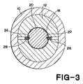
- Fig. 3 is a cross-section taken along the line III-III in Fig. 2.
- Fig. 4 is a cross-sectional view showing a modified embodiment of a reciprocating engine with three cylinders in a T-shaped arrangement.
- Fig. 5 is a plan view showing a still modified embodiment of a reciprocating engine with four cylinders in a X-shaped arrangement.
- Fig. 6 is a cross-section taken along the line VI-VI in Fig. 5.
- Fig. 7 is a view showing a still another embodiment of a reciprocating engine which provides two different and separate rotation at the same time.
- Fig. 8 is a front view showing a still another embodiment of the present invention which is designed as an air compressor.
- a shaft 1 is rotatably supported in a housing or cylinder (not shown). Shaft 1 is rotatably inserted into an inner bore (not shown) of a reciprocating element such as a piston (not shown).
- a pair of endless spiral grooves 2 and 3 are formed at an outer periphery of shaft 1.
- the first groove 2 starts from an uppermost point (a), traverses the second groove 3 at a point (b) and reaches an intermediate point (c) in a half-round trip on the outer periphery of shaft 1.
- the groove 2 makes another half-round trip on the other side (not shown in Fig. 1) of the outer periphery of shaft 1, wherein it traverses the second groove at a point (d) and then reaches an lowermost point (e).
- the groove 2 makes thus a first full-round trip by downward movement.
- a second full-round trip of the groove is achieved by its upward movement from the point (e), through a crossing point (f), the intermediate point (c) and another crossing point (g), located on the not-shown side of the periphery of shaft 1, to the starting uppermost point (a).
- Continuity of the second groove 2 starting from point (a) and returning to point (a) by successively passing through points (b), (c), (d), (e), (f), (c) and (g) will make a two-round trip on the outer periphery of shaft 1.
- the second groove 3 is formed at 180° offset with respect to the first groove 2.
- the second groove 3 starts from an uppermost point (h) and returns to the same point (h) by successively passing through the crossing point (g), an intermediate point (i), the crossing point (f), an lowermost point (j), the crossing point (d), the intermediate point (i) and the crossing point (b), during which the second groove 3 makes a two-round trip on the outer periphery of shaft 1.
- a pair of opposing projections or bosses 4 and 5 are engaged within grooves 2 and 3, respectively.
- Projections 4, 5 are moved up and down along with reciprocation of the piston.
- projection 4 is engaged within groove 2 at the uppermost point (a) and projection 5 is engaged within groove 3 at the uppermost point (h).
- projection 4 travels along groove 2 from point (a) to point (c) whereas projection 5 travels along groove 3 from point (h) to point (i), which makes a 180° counter-clockwise rotation of shaft 1.
- shaft 1 makes a full, 360° rotation during downward movement of the piston from T.D.C. to B.D.C.
- shaft 1 makes another full, 360° rotation during upward movement of the piston from B.D.C. to T.D.C.
- a ratio of reciprocation/rotation is 1:2, which is twice as large as the prior art. Moreover, such a ratio may be varied or increased by changing the number of rotation of spiral groove 4, 5 in its one complete trip around the outer periphery of shaft 1.
- the mechanism of the present invention requires no crank shaft as means for converting reciprocation of the piston to rotation. What are specially required are a simple straight extending shaft with spiral continuous grooves and projections cooperating the spiral grooves, which are easily machined and manufactured with an ordinary skill.
- Fig. 1 also illustrates a mechanism for converting rotation to reciprocation.
- shaft 1 is rotated by an electric motor (not shown) for example, projections 4, 5 are moved up and down while being engaged within grooves 2, 3.
- Fig. 2 illustrates a V2 engine into which the mechanism for transforming reciprocation to rotation (Fig. 1) is incorporated.
- Cylinders 10 and 10a are mounted in substantially V-shaped arrangement with 90° of bank. Cylinders 10 and 10a have substantially the same construction and therefore one cylinder 10 will be described in greater detail.
- Combustion chamber 16 of the illustrated embodiment is designed as substantially a hemispheroid, but may be differently shaped into something like a funnel, wedge, bath tab, for example.
- an intake manifold is provided for introducing a gas mixture of gasoline and air into combustion chamber 16, and an exhaust manifold is provided for discharging an exhaust gas from combustion chamber 16.
- the intake manifold and the exhaust manifold are provided with an inlet valve and an outlet valve respectively.
- Piston 12 reciprocates in an axial direction in stroke chamber 14 of cylinder 10.
- piston 12 makes two reciprocation during one complete cycle of operation including four strokes of gas-inlet, compression, explosion and exhaust.
- piston 12 is located at T.D.C.
- piston 14a of another cylinder 10a is located at B.D.C. as shown.
- Piston 12 has an inner bore 18 which is concentric with cylinder 10.
- Inner bore 18 has a closed upper end and an opened lower end through which a cylindrical shaft 20 is inserted.
- Shaft 20 is prevented from axial movement. Instead, shaft 20 is supported rotatably with respect to cylinder 10 and piston 12.
- a lubricating oil, bearings, white metal or any other means is provided on inner walls of bottom opening 11 of cylinder 10 and inner bore 18 of piston 12, which are at any time in contact with rotating shaft 20, for allowing smooth rotation of shaft 20 relative to cylinder 10 and piston 12.
- a pair of spiral grooves 22 and 24 are machined at an outer periphery of shaft 20.
- Grooves 22, 24 may be substantially the same as grooves 2, 3 shown in Fig. 1. More particularly, first groove 22 starts from an uppermost point 22a and reaches a lowermost point 22b, during which it makes a round of shaft 20. First groove 22 running upwardly from the lowermost point 22b to the uppermost point 22a makes another round of shaft 20. Similarly, second groove 24 makes a round of shaft 20 while running downwardly from an uppermost point 24a to a lowermost point 24b, and makes another round while running upwardly from the lowermost point 24b to the uppermost point 24a.
- Bosses 26, 28 projects toward inner bore 18 and are engaged within grooves 22, 24 respectively.
- boss 26 is engaged within groove 22 at its uppermost point 22a whereas boss 28 is engaged within groove 24 at its uppermost point 24a.
- Bosses 26, 28 are secured integrally with piston bottom 13 and therefore reciprocates in stroke chamber 14 together with piston 12.
- Shaft 20 extends through bottom opening 11 of cylinder 10 and has the lower end to which is secured a bevel gear 30.
- Bevel gear 30 is engaged with another bevel gear 32 mounted around a straight extending shaft 34.
- rotation of shaft 20 is transmitted to straight extending shaft 34 through engagement of bevel gears 30 and 32.
- spiral grooves 22, 24 makes another round of shaft 20 while running from the lowermost points 22b, 24b to the uppermost points 22a, 24a so that shaft 20 makes another one revolution during upward movement of piston 12 from B.D.C. to T.D.C.
- shaft 20 makes four revolution.
- Rotation of shaft 20 is transmitted to straight extending shaft 34 via bevel gears 30 and 32.
- the number of teeth of bevel gear 30, 32 are selected to be 20 and 10 respectively, which provides a gear ratio of 2
- two reciprocation of piston in a series of four cycle operation will be converted into eight revolution of straight extending shaft 34.
- the prior art four-cycle engine creates only two revolution of the crank shaft during the same two reciprocation of piston.
- flywheel 36 The end of straight extending shaft is connected a flywheel 36.
- a starter gear (not shown) is mounted in engagement with flywheel 36 for starting the engine with a cell motor (not shown).
- Pistons 12, 12a will move or reciprocate only in the axial direction and should be prevented from rotation. Should pistons 12, 12a rotate relative to grooved shafts 20, 20a, it becomes difficult or impossible to transmit movement of piston to grooved shaft. To this end, it is preferable that cylinder stroke chambers 14, 14a and pistons 12, 12a have oval cross-sections, as shown in Fig. 3.
- Revolution of straight extending shaft 34 depends on combination of the number of rounds of continuous spiral grooves 22, 24 and the gear ratio between bevel gears 30 and 32.
- revolution of straight extending shaft 34 may be selected within a relatively wide range so that in accordance with the present invention the reciprocating engine is designed to generate a greater output with a minimum fuel consumption.
- crank shaft which should be precisely manufactured, and the crank shaft is replaced by a straight extending shaft of a simple mechanism, thereby reducing an overall cost for manufacturing the engine.
- Fig. 2 illustrates an example of V-shaped arrangement. This arrangement may be modified into T-shaped arrangement as shown in Fig. 4 wherein a first cylinder 10 stands substantially upward and second and third cylinders 10a and 10b are mounted in opposed relation in a substantially horizontal plane. Cylinders 10a and 10b may be arranged in V-shape with an appropriate angle of bank.
- arrangement of Fig. 4 may further be modified to another arrangement in which four cylinders are arranged like a letter "X" or "+ " with a center shaft 34.
- a set of plural cylinders are mounted at the same location of straight extending shaft 34.
- a plural sets of cylinders may be mounted at different locations along straight extending shaft 34 with suitable spacings.
- two sets of four cylinders (X-shape arrangement) may be mounted at discrete two locations along shaft 34 to provide an engine having eight cylinders in a compact design.
- Figs. 5 and 6 show another arrangement of the reciprocating engine which has not been achievable by the prior art design.
- Four cylinders 40a to 40d are mounted in parallel relation and surround a straight extending center shaft 50.
- Each cylinder 40a-40d has substantially the same construction as cylinders 10, 10a of the arrangement of Fig. 2.
- Grooved shafts 42a-42d are rotated by reciprocation of pistons 44a-44d.
- gears 46a-46d To the lower ends of grooved shafts 42a-42d are secured gears 46a-46d which are all in engagement with a center gear 48 fitted around center shaft 50.
- a flywheel 52 is also secured around center shaft 50.
- This four-cylinder engine is extremely compact especially in its radial direction. Revolution of center shaft 50 depends on a gear ratio between gears 46a-46d and center gear 48, in combination with the number of rounds of grooves formed on shafts 42a-42d.
- Fig. 7 shows still another embodiment of a multiple-cylinder reciprocating engine of the present invention.
- This embodiment is so designed to cause at the same time a first shaft 52a to rotate in one direction and a second shaft 52b to rotate in the other direction.
- the engine has cylinders 54a-54f which may be constructed in the same manner as those 10, 10a in Fig. 2, 10, 10a and 10b in Fig. 4 and 40a-40d in Fig. 5.
- Bevel gears 58a-58f are connected to the lower ends of grooved shafts 56a-56f of cylinders 54a-54f, respectively. Bevel gears 58a and 58b are engaged with a first bevel gear 60a of first shaft 52a.
- Devel gears 58c and 58d are engaged with both a second bevel gear 60b of first shaft 52a and a second bevel gear 62b of second shaft 52b.
- Bevel gears 58e and 58f are engaged with a first bevel gear 62a of second shaft 52b.
- Flywheels 64a and 64b are secured around first and second shafts 52a and 52b respectively.
- reciprocation of pistons in four cylinders 54a-54d causes rotation of first shaft 52a and reciprocation of pistons in four cylinders 54c-54f causes rotation of second shaft 52b in a direction opposite to a rotating direction of first shaft 52a.
- This type of reciprocating engine is preferably mounted in sport type cars of high performance and of a four-wheel drive.
- Fig. 8 illustrates an air compressor employing a mechanism for converting rotation to reciprocation designed in accordance with a principle of the present invention.
- the air compressor 66 includes an electric motor 68 having an output shaft 68a with a reduction gearbox 70. Output shaft is connected to a grooved shaft 72.
- An oval cross-sectional piston 74 is reciprocatable in an oval cross-sectional chamber 76 of a cylinder 78.
- Piston 74 has an inner bore 80 for accommodating grooved shaft 72. It would be understood from the foregoing description of Fig. 1 that when motor 68 is driven to rotate grooved shaft 72, piston 74 is caused to reciprocate in chamber 76 due to engagement between projections (not shown) of piston 74 and grooves 82 of shaft 72.
- air is introduced into chamber 76 through an inlet 84 during leftward movement of piston 74 and discharged through an outlet 86 during rightward movement of piston 74.
- a plural cylinders 78 may be arranged and connected to a single motor 68 via gear engagement.
Landscapes
- Engineering & Computer Science (AREA)
- Mechanical Engineering (AREA)
- General Engineering & Computer Science (AREA)
- Chemical & Material Sciences (AREA)
- Combustion & Propulsion (AREA)
- Transmission Devices (AREA)
Applications Claiming Priority (2)
| Application Number | Priority Date | Filing Date | Title |
|---|---|---|---|
| JP278896/93 | 1993-10-13 | ||
| JP27889693A JPH07109931A (ja) | 1993-10-13 | 1993-10-13 | 往復運動を回転運動に変換する装置および該装置を用いたレシプロエンジン |
Publications (1)
| Publication Number | Publication Date |
|---|---|
| EP0648917A1 true EP0648917A1 (fr) | 1995-04-19 |
Family
ID=17603616
Family Applications (1)
| Application Number | Title | Priority Date | Filing Date |
|---|---|---|---|
| EP94307503A Withdrawn EP0648917A1 (fr) | 1993-10-13 | 1994-10-13 | Mécanisme pour la conversion des motions alternatives en motions rotatives et un projet d'un moteur à piston amélioré |
Country Status (2)
| Country | Link |
|---|---|
| EP (1) | EP0648917A1 (fr) |
| JP (1) | JPH07109931A (fr) |
Cited By (3)
| Publication number | Priority date | Publication date | Assignee | Title |
|---|---|---|---|---|
| GB2338030A (en) * | 1998-06-05 | 1999-12-08 | Gordon Lees Selman | I.c. engine with guide channel(s) instead of a crankshaft |
| GB2459025A (en) * | 2008-04-09 | 2009-10-14 | Daniel Lytton | Reciprocating-piston internal combustion engine with groove and follower instead of crank mechanism |
| FR2965014A1 (fr) * | 2010-09-21 | 2012-03-23 | Peugeot Citroen Automobiles Sa | Dispositif electrogene, systeme electrogene et vehicule comprenant un tel dispositif ou systeme electrogene |
Families Citing this family (1)
| Publication number | Priority date | Publication date | Assignee | Title |
|---|---|---|---|---|
| CN1142365C (zh) * | 2002-03-13 | 2004-03-17 | 梁锡昌 | 滚动螺旋发动机 |
Citations (4)
| Publication number | Priority date | Publication date | Assignee | Title |
|---|---|---|---|---|
| FR917216A (fr) * | 1944-04-26 | 1946-12-30 | Perfectionnements aux machines à piston | |
| US3192783A (en) * | 1962-09-28 | 1965-07-06 | Robert C Cruzan | Engine |
| US4366784A (en) * | 1981-03-16 | 1983-01-04 | Paul Brayton B | Crankless cam driven piston engine |
| US5203295A (en) * | 1992-08-27 | 1993-04-20 | Spiralex Corp. | Internal combustion engine |
-
1993
- 1993-10-13 JP JP27889693A patent/JPH07109931A/ja active Pending
-
1994
- 1994-10-13 EP EP94307503A patent/EP0648917A1/fr not_active Withdrawn
Patent Citations (4)
| Publication number | Priority date | Publication date | Assignee | Title |
|---|---|---|---|---|
| FR917216A (fr) * | 1944-04-26 | 1946-12-30 | Perfectionnements aux machines à piston | |
| US3192783A (en) * | 1962-09-28 | 1965-07-06 | Robert C Cruzan | Engine |
| US4366784A (en) * | 1981-03-16 | 1983-01-04 | Paul Brayton B | Crankless cam driven piston engine |
| US5203295A (en) * | 1992-08-27 | 1993-04-20 | Spiralex Corp. | Internal combustion engine |
Cited By (4)
| Publication number | Priority date | Publication date | Assignee | Title |
|---|---|---|---|---|
| GB2338030A (en) * | 1998-06-05 | 1999-12-08 | Gordon Lees Selman | I.c. engine with guide channel(s) instead of a crankshaft |
| GB2338030B (en) * | 1998-06-05 | 2002-04-10 | Gordon Lees Selman | Internal combustion engines |
| GB2459025A (en) * | 2008-04-09 | 2009-10-14 | Daniel Lytton | Reciprocating-piston internal combustion engine with groove and follower instead of crank mechanism |
| FR2965014A1 (fr) * | 2010-09-21 | 2012-03-23 | Peugeot Citroen Automobiles Sa | Dispositif electrogene, systeme electrogene et vehicule comprenant un tel dispositif ou systeme electrogene |
Also Published As
| Publication number | Publication date |
|---|---|
| JPH07109931A (ja) | 1995-04-25 |
Similar Documents
| Publication | Publication Date | Title |
|---|---|---|
| US5673665A (en) | Engine with rack gear-type piston rod | |
| EP0653013B1 (fr) | Moteur a air comprime | |
| AU738469B2 (en) | Reciprocating rotary piston system and pressure pump and internal combustion engine using the same | |
| US3572209A (en) | Radial engine | |
| JPWO2008010490A1 (ja) | サイクロイド往復動機関並びにこのクランク機構を用いたポンプ装置 | |
| US5873339A (en) | Bidirectionally reciprocating piston engine | |
| US10267225B2 (en) | Internal combustion engine | |
| US9169772B2 (en) | One-stroke internal combustion engine | |
| EP1170462B1 (fr) | Machine a piston comprenant un mecanisme sans bielle | |
| CN105247189A (zh) | 一冲程内燃机 | |
| CA1214995A (fr) | Machine a piston et parois de cylindre incorpores | |
| EP0648917A1 (fr) | Mécanisme pour la conversion des motions alternatives en motions rotatives et un projet d'un moteur à piston amélioré | |
| JP6754603B2 (ja) | 対向ピストン型エンジン | |
| US8573176B2 (en) | Crank chamber communication structure of multi-cylinder internal combustion engine | |
| JPH08178010A (ja) | 運動変換装置およびレシプロエンジン | |
| EP0662192B1 (fr) | Moteur a combustion interne | |
| EP0658689A1 (fr) | Moteur à combustion avec piston à double effet | |
| EP0628709B1 (fr) | Moteur à combustion interne | |
| US20210003121A1 (en) | Process for operating a single-stroke combustion engine | |
| CA2080132A1 (fr) | Moteur ou machine a combustion interne quadratique a pistons oscillants a double effet de forme rectangulaire et arquee | |
| US1149142A (en) | Internal-combustion engine. | |
| US9371775B2 (en) | One-stroke internal combustion engine | |
| US7296544B2 (en) | Internal combustion engine | |
| RU184024U1 (ru) | Газопоршневой двигатель внутреннего сгорания для отопления и вентиляции зданий | |
| WO2000036288A2 (fr) | Appariement de chambres de combustion dans des moteurs |
Legal Events
| Date | Code | Title | Description |
|---|---|---|---|
| PUAI | Public reference made under article 153(3) epc to a published international application that has entered the european phase |
Free format text: ORIGINAL CODE: 0009012 |
|
| AK | Designated contracting states |
Kind code of ref document: A1 Designated state(s): DE FR GB IT SE |
|
| STAA | Information on the status of an ep patent application or granted ep patent |
Free format text: STATUS: THE APPLICATION IS DEEMED TO BE WITHDRAWN |
|
| 18D | Application deemed to be withdrawn |
Effective date: 19951020 |