EP0649043B1 - Verminderung der Differenzbeugung in optischen Mehrstrahlabtastsystemen - Google Patents
Verminderung der Differenzbeugung in optischen Mehrstrahlabtastsystemen Download PDFInfo
- Publication number
- EP0649043B1 EP0649043B1 EP94307574A EP94307574A EP0649043B1 EP 0649043 B1 EP0649043 B1 EP 0649043B1 EP 94307574 A EP94307574 A EP 94307574A EP 94307574 A EP94307574 A EP 94307574A EP 0649043 B1 EP0649043 B1 EP 0649043B1
- Authority
- EP
- European Patent Office
- Prior art keywords
- lens
- light beams
- scan
- field curvature
- bow
- Prior art date
- Legal status (The legal status is an assumption and is not a legal conclusion. Google has not performed a legal analysis and makes no representation as to the accuracy of the status listed.)
- Expired - Lifetime
Links
- 230000003287 optical effect Effects 0.000 title claims description 19
- 108091008695 photoreceptors Proteins 0.000 description 15
- 210000001747 pupil Anatomy 0.000 description 6
- 238000003384 imaging method Methods 0.000 description 2
- 238000000926 separation method Methods 0.000 description 2
- 238000010276 construction Methods 0.000 description 1
- 230000000694 effects Effects 0.000 description 1
- 238000000034 method Methods 0.000 description 1
Images



Classifications
-
- G—PHYSICS
- G02—OPTICS
- G02B—OPTICAL ELEMENTS, SYSTEMS OR APPARATUS
- G02B27/00—Optical systems or apparatus not provided for by any of the groups G02B1/00 - G02B26/00, G02B30/00
- G02B27/0025—Optical systems or apparatus not provided for by any of the groups G02B1/00 - G02B26/00, G02B30/00 for optical correction, e.g. distorsion, aberration
- G02B27/0031—Optical systems or apparatus not provided for by any of the groups G02B1/00 - G02B26/00, G02B30/00 for optical correction, e.g. distorsion, aberration for scanning purposes
Definitions
- the rotating polygon 18 has a plurality of facets 26, each of which is a plane mirror.
- the facets 26 of the rotating polygon mirror 18 reflect the light beam 24 and also cause the reflected light 24 to revolve about an axis near the reflection point of the facet 26 of the rotating polygon mirror 18.
- This reflected light beam can be utilized through the post polygon optics 20 to scan a document at the input end of an imaging system as a raster input scanner or can be used to impinge upon a photographic film or a photosensitive medium 22, such as a xerographic drum (photoreceptor), at the output of the imaging system.
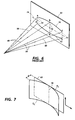
- a differential bow happens in multi-beam raster scanners in which the light beams are nominally off-axis in the cross scan direction. For example, referring to Figure 4, if the bow of one beam happens to be a smile while the bow of the other beam happens to be a frown, then the two beams create two lines 38 and 39 in which the separation between the two beams varies across the scan. This phenomenon is called a differential bow. It should be noted that a differential bow can have different shapes such as two scan lines with the same shape bow but a different amount of bow on each scan line or two scan lines with a smile on the top scan line and a frown on the bottom scan line. It is desirable to have all the scan lines straight and parallel so that the beam separation across the scan line would be uniform and therefore, the differential bow would be eliminated.
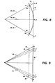
- the light beam For any point other than the center of the scan the light beam focuses on the field curvature before it reaches the photoreceptor plane 62.
- the light beam 48 at the start of the scan instead of focusing at point a, focuses at point 76 on the field curvature Fc and at the end of the scan, instead of focusing at point c, focuses at point 78 on the field curvature Fc.
- the light beam 50 at the start of the scan instead of focusing at point d it focuses at point 80 on the field curvature FC and at the end of the scan instead of focusing at point f it focuses at point 82 on the field curvature Fc.
Landscapes
- Physics & Mathematics (AREA)
- General Physics & Mathematics (AREA)
- Optics & Photonics (AREA)
- Mechanical Optical Scanning Systems (AREA)
- Details Of Television Scanning (AREA)
Claims (6)
- Ein Rasterabtastsystem, das umfaßt:dadurch gekennzeichnet, daß die genannte zweite Linse (90) eine zylindrisch konkave Fläche (94) in Querabtastrichtung aufweist, um die Lichtbündel von der genannten ersten optischen Einrichtung aufzunehmen, und eine konvexe Fläche (96), durch die die Lichtbündel austreten,zwei Lichtquellen (44, 46), von denen jede ein Lichtbündel (48, 50) entlang eines Weges aussendet;ein lichtempfindliches Medium (62);eine Abtasteinrichtung (58), die sich in dem Weg der Lichtbündel von den genannten zwei Lichtquellen befindet und so konstruiert und angeordnet ist, daß die Lichtbündel in einer tangentialen Ebene über das genannte photoempfindliche Material abtasten;eine erste Linse (98), die sich in dem Weg der Lichtbündel von der genannten Abtasteinrichtung befindet, und eine konkave Fläche (102), um die Lichtbündel von der genannten Abtasteinrichtung aufzunehmen, und eine ebene Fläche aufweist, durch die die Lichtbündel austreten;eine zweite Linse (90), die sich in dem Weg der Lichtbündel von der genannten ersten Linse befindet;einen zylindrisch konkaven Querabtastspiegel (92), der sich in dem Weg der Lichtbündel von der genannten zweiten Linse befindet, um die Lichtbündel auf das genannte Medium zu reflektieren;daß die genannte zweite Linse (90) und der genannte Spiegel (92) so konstruiert und in Bezug zueinander derart angeordnet sind, daß die genannte konkave Fläche der genannten zweiten Linse und der genannte Spiegel eine Feldkrümmung erzeugen, um im wesentlichen die Bogendifferenz zwischen den Lichtbündeln zu verringern.
- Ein Rasterabtastsystem, gemäß Anspruch 1, wobei eine zylindrisch konvexe Fläche (100) in Querabtastrichtung, durch die die Lichtbündel austreten, der ebenen Fläche der genannten ersten Linse (98) hinzugefügt ist, und die genannte erste Linse (98), die genannte zweite Linse (90) und der genannte Spiegel (92) in Bezug zueinander angeordnet sind, um die erzeugte Feldkrümmung wesentlich zu verringern.
- Das Rasterabtastsystem, das in Anspruch 1 oder 2 genannt worden ist, wobei die konkave Fläche (102) der genannten ersten Linse (98) sphärisch ist.
- Das Rasterabtastsystem, das in Anspruch 1, 2 oder 3 genannt worden ist, wobei die konkave Fläche (102) der genannten ersten Linse (98) zylindrisch ist.
- Das Rasterabtastsystem, das in irgendeinem der vorhergehenden Ansprüche genannt worden ist, wobei die konvexe Fläche (96) der genannten zweiten Linse (90) sphärisch ist.
- Das Rasterabtastsystem, das in irgendeinem der vorhergehenden Ansprüche genannt worden ist, wobei die konvexe Fläche (96) der genannten zweiten Linse (90) zylindrisch ist.
Applications Claiming Priority (2)
| Application Number | Priority Date | Filing Date | Title |
|---|---|---|---|
| US13564193A | 1993-10-14 | 1993-10-14 | |
| US135641 | 1993-10-14 |
Publications (2)
| Publication Number | Publication Date |
|---|---|
| EP0649043A1 EP0649043A1 (de) | 1995-04-19 |
| EP0649043B1 true EP0649043B1 (de) | 1999-07-28 |
Family
ID=22468981
Family Applications (1)
| Application Number | Title | Priority Date | Filing Date |
|---|---|---|---|
| EP94307574A Expired - Lifetime EP0649043B1 (de) | 1993-10-14 | 1994-10-14 | Verminderung der Differenzbeugung in optischen Mehrstrahlabtastsystemen |
Country Status (4)
| Country | Link |
|---|---|
| US (1) | US5517330A (de) |
| EP (1) | EP0649043B1 (de) |
| JP (1) | JPH07199109A (de) |
| DE (1) | DE69419689T2 (de) |
Families Citing this family (20)
| Publication number | Priority date | Publication date | Assignee | Title |
|---|---|---|---|---|
| JPH0980330A (ja) * | 1995-09-07 | 1997-03-28 | Minolta Co Ltd | マルチビーム走査光学系 |
| IL115864A (en) * | 1995-11-02 | 1999-05-09 | Orbotech Ltd | Method and apparatus for delivering laser energy to an object |
| US6069723A (en) * | 1996-08-26 | 2000-05-30 | Ricoh Company, Ltd. | Multi-beam scanning apparatus with controlled scan line bow |
| US6108025A (en) * | 1997-09-29 | 2000-08-22 | Eastman Kodak Company | Optical scanner system having a laser beam power attentuation mechanism |
| US5956071A (en) * | 1997-09-29 | 1999-09-21 | Eastman Kodak Company | Mechanism for positioning film into a scanning position in an internal drum laser scanner assembly |
| US6002524A (en) * | 1997-09-29 | 1999-12-14 | Imation Corp. | Flexible lens |
| US6057537A (en) * | 1997-09-29 | 2000-05-02 | Eastman Kodak Company | Optical scanner feedback system having a reflected cylinder lens |
| US6064416A (en) * | 1997-09-29 | 2000-05-16 | Eastman Kodak Company | Linear translation system for use in a laser imaging system |
| US5883658A (en) * | 1997-09-29 | 1999-03-16 | Imation Corp. | Optical scanner assembly for use in a laser imaging system |
| US5900963A (en) * | 1997-09-29 | 1999-05-04 | Imation Corp. | Optical scanner system |
| US5933268A (en) * | 1997-09-29 | 1999-08-03 | Imation Corp. | Optical configuration for an optical scanner system |
| US5932151A (en) * | 1997-09-29 | 1999-08-03 | Imation Corp. | Method of making a flexible lens |
| US6061080A (en) * | 1998-01-30 | 2000-05-09 | Xerox Corporation | Aperture for multiple reflection raster output scanning system to reduce bow |
| US6094287A (en) * | 1998-12-03 | 2000-07-25 | Eastman Kodak Company | Wobble correcting monogon scanner for a laser imaging system |
| US6104523A (en) * | 1998-12-21 | 2000-08-15 | Xerox Corporation | Dual beam double pass raster output scanner |
| US6057953A (en) * | 1998-12-21 | 2000-05-02 | Xerox Corporation | Dual beam double pass raster output scanner |
| JP2001215423A (ja) | 2000-02-04 | 2001-08-10 | Fuji Xerox Co Ltd | 光走査方法及び光走査装置 |
| US6496215B2 (en) * | 2000-12-15 | 2002-12-17 | Xerox Corporation | Thermal scan line bow adjustment in an optical scanning system |
| KR100445128B1 (ko) * | 2002-06-05 | 2004-08-21 | 삼성전자주식회사 | 광주사장치 |
| US10634271B2 (en) | 2016-02-04 | 2020-04-28 | Felix Sorkin | Bayonet duct coupler assembly for post-tensioned concrete member |
Family Cites Families (10)
| Publication number | Priority date | Publication date | Assignee | Title |
|---|---|---|---|---|
| US4139257A (en) * | 1976-09-28 | 1979-02-13 | Canon Kabushiki Kaisha | Synchronizing signal generator |
| US4247160A (en) * | 1979-03-26 | 1981-01-27 | Xerox Corporation | Scanner with reflective pyramid error compensation |
| SE433783B (sv) * | 1982-03-03 | 1984-06-12 | Pharos Ab | Optisk svepanordning |
| US4512625A (en) * | 1982-10-08 | 1985-04-23 | Xerox Corporation | Scanner optics with no cross scan field curvature |
| US4805974A (en) * | 1987-11-02 | 1989-02-21 | Xerox Corporation | Polycone™ scanning system with multiple beams |
| JPH0364726A (ja) * | 1989-08-02 | 1991-03-20 | Minolta Camera Co Ltd | 光ビーム走査光学系 |
| JP2610352B2 (ja) * | 1990-02-28 | 1997-05-14 | 大日本スクリーン製造株式会社 | 光ビーム走査装置 |
| US5153768A (en) * | 1990-03-08 | 1992-10-06 | Xerox Corporation | Multiple wavelength, multiple diode laser ROS |
| JPH04233867A (ja) * | 1990-06-27 | 1992-08-21 | Xerox Corp | サブミクロンの揺動補正を有する光学的走査システム |
| US5333067A (en) * | 1991-10-29 | 1994-07-26 | Olive Tree Technology, Inc. | Apparatus and method for velocity compensation of the scanning spot in non-linear scanning systems |
-
1994
- 1994-10-05 JP JP6240924A patent/JPH07199109A/ja not_active Ceased
- 1994-10-14 DE DE69419689T patent/DE69419689T2/de not_active Expired - Fee Related
- 1994-10-14 EP EP94307574A patent/EP0649043B1/de not_active Expired - Lifetime
- 1994-10-25 US US08/329,011 patent/US5517330A/en not_active Expired - Lifetime
Also Published As
| Publication number | Publication date |
|---|---|
| DE69419689D1 (de) | 1999-09-02 |
| US5517330A (en) | 1996-05-14 |
| JPH07199109A (ja) | 1995-08-04 |
| EP0649043A1 (de) | 1995-04-19 |
| DE69419689T2 (de) | 1999-12-23 |
Similar Documents
| Publication | Publication Date | Title |
|---|---|---|
| US5517330A (en) | Minimization of differential bow in multiple beam scanning optical systems | |
| JP3193546B2 (ja) | 反射型走査光学系 | |
| EP1111435B1 (de) | Optischer Rasterabtaster mit reduzierter Bauhöhe erreicht durch mehrere Schwankungskorrekturelemente | |
| US5512949A (en) | Multiple beam raster output scanner optical system having telecentric chief exit rays | |
| JP3222023B2 (ja) | 光走査装置 | |
| EP0713323B1 (de) | Vielpunkt-Polygonrasterausgabeabtaster mit optimierter Linienabstandsschärfentiefe | |
| JP3513724B2 (ja) | ラスタ走査システム | |
| EP0454503B1 (de) | Optische Abtaster | |
| JP2524567B2 (ja) | 複数ビ―ム走査光学装置 | |
| US6075638A (en) | Scanning and imaging lens and optical scanning device | |
| US5969877A (en) | Dual wavelength F-theta scan lens | |
| US6266174B1 (en) | Multi-beam scanning apparatus with controlled scan line bow | |
| US5383047A (en) | Ros bow compensation | |
| US6061080A (en) | Aperture for multiple reflection raster output scanning system to reduce bow | |
| US5966232A (en) | Scanning optical system | |
| JP3197804B2 (ja) | マルチビーム走査装置 | |
| US5343326A (en) | Compact ros imaging system | |
| KR100683189B1 (ko) | 레이저 스캐닝 장치 | |
| US5381259A (en) | Raster output scanner (ROS) using an overfilled polygon design with minimized optical path length | |
| JP2907292B2 (ja) | 色消しレーザ走査光学系 | |
| JPH04283717A (ja) | 画像形成装置における光走査装置 | |
| JPH01200220A (ja) | 光ビーム走査光学系 | |
| JP2003107384A (ja) | 反射型走査光学系 | |
| JPH10186256A (ja) | 走査光学系及びマルチビーム走査光学系 | |
| JPH01200219A (ja) | 光ビーム走査光学系 |
Legal Events
| Date | Code | Title | Description |
|---|---|---|---|
| PUAI | Public reference made under article 153(3) epc to a published international application that has entered the european phase |
Free format text: ORIGINAL CODE: 0009012 |
|
| AK | Designated contracting states |
Kind code of ref document: A1 Designated state(s): DE FR GB |
|
| 17P | Request for examination filed |
Effective date: 19951019 |
|
| 17Q | First examination report despatched |
Effective date: 19960104 |
|
| GRAG | Despatch of communication of intention to grant |
Free format text: ORIGINAL CODE: EPIDOS AGRA |
|
| GRAG | Despatch of communication of intention to grant |
Free format text: ORIGINAL CODE: EPIDOS AGRA |
|
| GRAH | Despatch of communication of intention to grant a patent |
Free format text: ORIGINAL CODE: EPIDOS IGRA |
|
| GRAH | Despatch of communication of intention to grant a patent |
Free format text: ORIGINAL CODE: EPIDOS IGRA |
|
| GRAA | (expected) grant |
Free format text: ORIGINAL CODE: 0009210 |
|
| AK | Designated contracting states |
Kind code of ref document: B1 Designated state(s): DE FR GB |
|
| REF | Corresponds to: |
Ref document number: 69419689 Country of ref document: DE Date of ref document: 19990902 |
|
| ET | Fr: translation filed | ||
| PLBE | No opposition filed within time limit |
Free format text: ORIGINAL CODE: 0009261 |
|
| STAA | Information on the status of an ep patent application or granted ep patent |
Free format text: STATUS: NO OPPOSITION FILED WITHIN TIME LIMIT |
|
| 26N | No opposition filed | ||
| PGFP | Annual fee paid to national office [announced via postgrant information from national office to epo] |
Ref country code: FR Payment date: 20011010 Year of fee payment: 8 |
|
| PGFP | Annual fee paid to national office [announced via postgrant information from national office to epo] |
Ref country code: GB Payment date: 20011017 Year of fee payment: 8 |
|
| PGFP | Annual fee paid to national office [announced via postgrant information from national office to epo] |
Ref country code: DE Payment date: 20011029 Year of fee payment: 8 |
|
| REG | Reference to a national code |
Ref country code: GB Ref legal event code: IF02 |
|
| PG25 | Lapsed in a contracting state [announced via postgrant information from national office to epo] |
Ref country code: GB Free format text: LAPSE BECAUSE OF NON-PAYMENT OF DUE FEES Effective date: 20021014 |
|
| PG25 | Lapsed in a contracting state [announced via postgrant information from national office to epo] |
Ref country code: DE Free format text: LAPSE BECAUSE OF NON-PAYMENT OF DUE FEES Effective date: 20030501 |
|
| GBPC | Gb: european patent ceased through non-payment of renewal fee |
Effective date: 20021014 |
|
| PG25 | Lapsed in a contracting state [announced via postgrant information from national office to epo] |
Ref country code: FR Free format text: LAPSE BECAUSE OF NON-PAYMENT OF DUE FEES Effective date: 20030630 |
|
| REG | Reference to a national code |
Ref country code: FR Ref legal event code: ST |