EP0649076A2 - Petite montre contrôlée par radio - Google Patents
Petite montre contrôlée par radio Download PDFInfo
- Publication number
- EP0649076A2 EP0649076A2 EP94115907A EP94115907A EP0649076A2 EP 0649076 A2 EP0649076 A2 EP 0649076A2 EP 94115907 A EP94115907 A EP 94115907A EP 94115907 A EP94115907 A EP 94115907A EP 0649076 A2 EP0649076 A2 EP 0649076A2
- Authority
- EP
- European Patent Office
- Prior art keywords
- circuit board
- core
- radio clock
- coil
- clock according
- Prior art date
- Legal status (The legal status is an assumption and is not a legal conclusion. Google has not performed a legal analysis and makes no representation as to the accuracy of the status listed.)
- Granted
Links
Images
Classifications
-
- G—PHYSICS
- G04—HOROLOGY
- G04G—ELECTRONIC TIME-PIECES
- G04G21/00—Input or output devices integrated in time-pieces
- G04G21/04—Input or output devices integrated in time-pieces using radio waves
-
- G—PHYSICS
- G04—HOROLOGY
- G04R—RADIO-CONTROLLED TIME-PIECES
- G04R60/00—Constructional details
-
- G—PHYSICS
- G04—HOROLOGY
- G04R—RADIO-CONTROLLED TIME-PIECES
- G04R60/00—Constructional details
- G04R60/02—Antennas also serving as components of clocks or watches, e.g. motor coils
-
- G—PHYSICS
- G04—HOROLOGY
- G04R—RADIO-CONTROLLED TIME-PIECES
- G04R60/00—Constructional details
- G04R60/06—Antennas attached to or integrated in clock or watch bodies
- G04R60/10—Antennas attached to or integrated in clock or watch bodies inside cases
-
- H—ELECTRICITY
- H01—ELECTRIC ELEMENTS
- H01Q—ANTENNAS, i.e. RADIO AERIALS
- H01Q1/00—Details of, or arrangements associated with, antennas
- H01Q1/27—Adaptation for use in or on movable bodies
- H01Q1/273—Adaptation for carrying or wearing by persons or animals
-
- H—ELECTRICITY
- H04—ELECTRIC COMMUNICATION TECHNIQUE
- H04B—TRANSMISSION
- H04B15/00—Suppression or limitation of noise or interference
- H04B15/02—Reducing interference from electric apparatus by means located at or near the interfering apparatus
Definitions
- the invention relates to a radio clock according to the preamble of claim 1.
- Such a radio clock is known from EP 0 531 853 A2.
- a disc-shaped core of the magnetic long-wave antenna itself serves, as it were, as a work plate, apart from the core part designed as a coil carrier.
- the wheel and pointer movement, including its electromotive step drive, as well as the electronic circuits for autonomous clock operation and for display correction information, which are obtained from received and decoded time telegrams, are mounted on these and, if necessary, projecting into them.
- a recording area for an electro-optical digital display is incorporated into the flat core.
- miniaturized precision castings made of plastic can be inserted into the core for the gear train storage.
- the problem with such a structure is the proximity of the electronic evaluation circuit on the one hand and on the other hand the electromechanical pointer drive to the magnetic long-wave antenna in the form of the core with its Antenna coil, since electromagnetic interference originating from the electronic and electromechanical circuits can be increasingly fed back via the antenna effect.
- the operation of a watch equipped in this way with an increased reception field strength should therefore be aimed at, but this limits the area of application with regard to the distance from the transmitter of the time telegrams.
- the invention has for its object to design a radio clock of the generic type in such a way that effective suppression of the electromagnetic interference from functional components that work in the immediate vicinity of the antenna core itself is ensured without great additional construction effort and without unreasonably impairing the antenna performance.
- the core of the magnetic long-wave antenna itself continues to serve as a carrier for the electronic and electromechanical functional parts of the watch, but it covers the essential interferers in such a way that their interference effects on the antenna coil largely compensate themselves geometrically (vectorially).
- the core surrounding the movement and covered by the dial can be designed as a watch case.
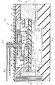
- the capacitive resonance-tuned magnetic long-wave antenna 11 of the radio watch 12 which is preferably designed as a wristwatch, consists of a large-volume flat ferrite core 13 with antenna coil 14.
- the disk-shaped core 13 fills the interior 16 of a flat one -pot-shaped plastic watch case 15 in essential.
- a taper that is eccentric with respect to the vertical axis 10 of the core 13 serves as a carrier body for the coil 14.
- a region of the flat surface 33 of the core 13 which is remote from the housing bottom 22 serves as a support for a flange 34 which is covered with a dial 23.
- the flange 34 surrounds the opening of a molded plastic pot 35, which projects with its bottom 36 into a central hole 28 in the core 13 into the area of its central plane 37.
- the printed circuit board 26 for at least the most important components of the electronic circuits for autonomous time-keeping operation of the radio clock 12, for receiving and decoding of the absolute time information, and for checking and, if necessary, correcting the current time display on the basis of the received current time information, is fastened under the pot base 36 .
- the core 13 thus surrounds the edge of the main plane of the printed circuit board 26 with its components.
- the wheels and pointer mechanism 27 together with the electromechanical stepping motor for moving the pointer 30 is arranged inside the pot 35, with bearing points 39 for journal bearings in the base 36 and in a bridge 40 spanning the pot opening under the dial 23.
- a battery 29 dips opposite, that is to say from the underside of the core 13 and supported on the housing base 22, into the through hole 28 which is concentric with the work axis 19.
- the currents flowing through the conductor tracks 38 to the components of the circuit can result in such strong electromagnetic interference for the function of the antenna 11 that they require effective shielding measures which are effective in themselves, that is to say are electrically conductive and highly permeable. Because with the integral structure, disruptive couplings can no longer be excluded by the otherwise usual observance of a minimum constructive distance between the printed circuit board 26 and the antenna 11. However, the geometric design and the technical installation, for example, of shielding hoods are very complex, and the damping effect of additional shielding measures directly on the magnetic antenna 11 leads to the fact that this becomes less sensitive and thus correct reception operation only with a higher reception field strength, that is to say among the better ones Reception conditions in closer proximity to the transmitter, can be ensured.
- a concentrated interferer especially in the form of a component with clocked internal current flows, can also be arranged in the plane of symmetry of the coil 14, i.e. centered on its coil axis 18, the interference is further reduced because the magnetic field components run approximately transversely to the coil axis , so practically no winding surface.
- the strongest interferer with an electromechanically operated clock 12 is the field coil of the stepper motor. Its stator would therefore also be expediently arranged as far away from the coil 14 as possible but in the plane of its axis 18. That is, however, in the case of a radio clock 12 which is very small in diameter and is designed approximately as a wristwatch not feasible for reasons of space, especially since the transmission connection to the wheels factory 27 must also be guaranteed. Therefore, the stepper motor is conveniently arranged laterally next to the work 27 inside the pot 35 made of electrically and magnetically non-conductive material. In this asymmetrical position with respect to the antenna axis 18-37 there is no longer any geometric compensation of the interference fields acting on the coil 14 from the motor.
- the radio clock 12 is only equipped with minute and hour hands 30, only one step control of the movement 27 needs to be carried out from the motor per minute; the motor can be electrically switched off in the remaining 59 seconds per minute.
- the processor 41 which also controls the motor operation, the receiver 42 is therefore stopped for the duration of the motor operation, the reception operation is therefore limited to the sufficiently long pause time of the motor operation and in this way the interference from the stepper motor is not geometrically compensated, but also effectively electrically hidden.
- an additional printed circuit board can be arranged in the plane between the gear train bridge 40 and the dial 23. The is then not symmetrical in the core 13 or with respect to the coil axis 18, but the disruptive effect of their currents is z. B. limited to the operating period of the engine, in which the receiver 41 is now switched off. For the rest, signals can also be routed via this additional circuit board, which only require a rare current flow, such as, for example, push buttons located on the edge of the circuit board (and thus operable through the watch housing).
- the transmitter or receiver of a fork light barrier 44 can also be arranged on that additional circuit board which is arranged opposite and parallel to the main circuit board 26 with respect to the work 27.
- the complementary element of the light barrier 44 is arranged on the laminated side of the main circuit board 26 and projects into an opening 45 in the pot base 36. If it is the transmit / receive element 46 of a reflex light barrier 44, then only one reflector 47 need be formed on the bridge 40.
- the light barrier 44 is continuous when aperture holes 48 are coaxially aligned with one another, which are formed in the intermediate gear 49 (driven by the motor pinion), in the minute wheel 50 driven by the pinion and in the hour wheel 51, with a gear coupling between the latter two via that of the Light barrier 44 not detected change wheel 52.
- aperture holes 48 are just then and only when the hands 30 are in a defined reference direction (preferably both aligned with the 12 o'clock mark). From this reference position, the pivoting of the pointers 30 into the display position is then monitored in the processor 41, which corresponds to the current time and verified by radio, as in DE-PS 3510861 also for differently designed gear trains (for example with two electrically coupled motors) described.
Landscapes
- Physics & Mathematics (AREA)
- General Physics & Mathematics (AREA)
- Engineering & Computer Science (AREA)
- Computer Networks & Wireless Communication (AREA)
- Signal Processing (AREA)
- Electromechanical Clocks (AREA)
- Electric Clocks (AREA)
- Magnetic Resonance Imaging Apparatus (AREA)
- Inorganic Insulating Materials (AREA)
- Diaphragms For Electromechanical Transducers (AREA)
- Control Of Position Or Direction (AREA)
- Toys (AREA)
Applications Claiming Priority (2)
| Application Number | Priority Date | Filing Date | Title |
|---|---|---|---|
| DE9315669U | 1993-10-14 | ||
| DE9315669U DE9315669U1 (de) | 1993-10-14 | 1993-10-14 | Kleine Funkuhr |
Publications (3)
| Publication Number | Publication Date |
|---|---|
| EP0649076A2 true EP0649076A2 (fr) | 1995-04-19 |
| EP0649076A3 EP0649076A3 (fr) | 1997-01-15 |
| EP0649076B1 EP0649076B1 (fr) | 1998-03-11 |
Family
ID=6899410
Family Applications (1)
| Application Number | Title | Priority Date | Filing Date |
|---|---|---|---|
| EP94115907A Expired - Lifetime EP0649076B1 (fr) | 1993-10-14 | 1994-10-08 | Petite montre contrÔlée par radio |
Country Status (5)
| Country | Link |
|---|---|
| US (1) | US5430693A (fr) |
| EP (1) | EP0649076B1 (fr) |
| AT (1) | ATE164014T1 (fr) |
| DE (2) | DE9315669U1 (fr) |
| ES (1) | ES2115129T3 (fr) |
Families Citing this family (21)
| Publication number | Priority date | Publication date | Assignee | Title |
|---|---|---|---|---|
| JPH09166671A (ja) * | 1995-09-28 | 1997-06-24 | Helmut Hechinger Gmbh & Co | 時計針の位置決め装置 |
| EP0802637B1 (fr) * | 1995-11-06 | 2004-03-24 | Seiko Epson Corporation | Dispositif de communication |
| DE29714185U1 (de) * | 1997-08-08 | 1998-12-03 | Gebrüder Junghans GmbH, 78713 Schramberg | Funkarmbanduhr |
| US6062985A (en) * | 1998-05-06 | 2000-05-16 | Rege; Kathleen | Golf flag stick play pacer |
| US6269055B1 (en) | 1998-11-16 | 2001-07-31 | Quartex, A Division Of Primex, Inc. | Radio-controlled clock movement |
| JP3395786B1 (ja) * | 2002-02-26 | 2003-04-14 | セイコーエプソン株式会社 | 電子機器、電子機器の受信制御方法および電子機器の受信制御プログラム |
| US7167140B2 (en) * | 2003-07-02 | 2007-01-23 | Nec Tokin Corporation | Coil antenna |
| JP2006234436A (ja) * | 2005-02-22 | 2006-09-07 | Seiko Instruments Inc | 電波時計 |
| US10451897B2 (en) | 2011-03-18 | 2019-10-22 | Johnson & Johnson Vision Care, Inc. | Components with multiple energization elements for biomedical devices |
| US9812730B2 (en) | 2011-08-02 | 2017-11-07 | Johnson & Johnson Vision Care, Inc. | Biocompatible wire battery |
| US8857983B2 (en) | 2012-01-26 | 2014-10-14 | Johnson & Johnson Vision Care, Inc. | Ophthalmic lens assembly having an integrated antenna structure |
| US9599842B2 (en) | 2014-08-21 | 2017-03-21 | Johnson & Johnson Vision Care, Inc. | Device and methods for sealing and encapsulation for biocompatible energization elements |
| US9715130B2 (en) | 2014-08-21 | 2017-07-25 | Johnson & Johnson Vision Care, Inc. | Methods and apparatus to form separators for biocompatible energization elements for biomedical devices |
| US9793536B2 (en) | 2014-08-21 | 2017-10-17 | Johnson & Johnson Vision Care, Inc. | Pellet form cathode for use in a biocompatible battery |
| US9941547B2 (en) | 2014-08-21 | 2018-04-10 | Johnson & Johnson Vision Care, Inc. | Biomedical energization elements with polymer electrolytes and cavity structures |
| US10361404B2 (en) | 2014-08-21 | 2019-07-23 | Johnson & Johnson Vision Care, Inc. | Anodes for use in biocompatible energization elements |
| US10627651B2 (en) | 2014-08-21 | 2020-04-21 | Johnson & Johnson Vision Care, Inc. | Methods and apparatus to form biocompatible energization primary elements for biomedical devices with electroless sealing layers |
| US10361405B2 (en) | 2014-08-21 | 2019-07-23 | Johnson & Johnson Vision Care, Inc. | Biomedical energization elements with polymer electrolytes |
| US10381687B2 (en) | 2014-08-21 | 2019-08-13 | Johnson & Johnson Vision Care, Inc. | Methods of forming biocompatible rechargable energization elements for biomedical devices |
| US9383593B2 (en) | 2014-08-21 | 2016-07-05 | Johnson & Johnson Vision Care, Inc. | Methods to form biocompatible energization elements for biomedical devices comprising laminates and placed separators |
| US10345620B2 (en) | 2016-02-18 | 2019-07-09 | Johnson & Johnson Vision Care, Inc. | Methods and apparatus to form biocompatible energization elements incorporating fuel cells for biomedical devices |
Family Cites Families (4)
| Publication number | Priority date | Publication date | Assignee | Title |
|---|---|---|---|---|
| DE8432847U1 (de) * | 1984-11-09 | 1985-05-30 | Gebrueder Junghans Gmbh, 7230 Schramberg | Zeigerstellungs-Detektionseinrichtung für eine Uhr, insbesondere eine Funkuhr |
| DE8901512U1 (de) * | 1989-02-10 | 1990-06-13 | Junghans Uhren GmbH, 7230 Schramberg | Kleine Funkuhr mit Antennenspule |
| DE9010813U1 (de) * | 1990-07-20 | 1991-11-14 | Junghans Uhren GmbH, 7230 Schramberg | Autonome Funkuhr |
| DE9111096U1 (de) * | 1991-09-07 | 1993-01-07 | Junghans Uhren GmbH, 7230 Schramberg | Funkuhr-Werk |
-
1993
- 1993-10-14 DE DE9315669U patent/DE9315669U1/de not_active Expired - Lifetime
-
1994
- 1994-10-08 DE DE59405417T patent/DE59405417D1/de not_active Expired - Fee Related
- 1994-10-08 AT AT94115907T patent/ATE164014T1/de not_active IP Right Cessation
- 1994-10-08 EP EP94115907A patent/EP0649076B1/fr not_active Expired - Lifetime
- 1994-10-08 ES ES94115907T patent/ES2115129T3/es not_active Expired - Lifetime
- 1994-10-12 US US08/321,445 patent/US5430693A/en not_active Expired - Fee Related
Also Published As
| Publication number | Publication date |
|---|---|
| EP0649076B1 (fr) | 1998-03-11 |
| ES2115129T3 (es) | 1998-06-16 |
| US5430693A (en) | 1995-07-04 |
| DE9315669U1 (de) | 1995-02-09 |
| DE59405417D1 (de) | 1998-04-16 |
| ATE164014T1 (de) | 1998-03-15 |
| EP0649076A3 (fr) | 1997-01-15 |
Similar Documents
| Publication | Publication Date | Title |
|---|---|---|
| EP0649076B1 (fr) | Petite montre contrÔlée par radio | |
| DE29714185U1 (de) | Funkarmbanduhr | |
| DE3627193C2 (fr) | ||
| EP1067442B2 (fr) | Bracelet-montre radio | |
| DE60204050T2 (de) | Vhf-wellenempfängerantenne, die in einem armband einer tragbaren elektronischen einrichtung untergebracht ist | |
| EP0180880A2 (fr) | Dispositif de détection de la position de l'affichage d'une montre, en particulier une montre à radiocommande | |
| EP1520346B1 (fr) | Dispositif de reglage d'angles de rotation | |
| EP1202024B1 (fr) | Module de capteur avec une plaque de métal découpée ( capteur magnéto résistif vanne papillon ) | |
| DE4432000C2 (de) | Drahtlos gesteuerte Wegfahrsperre für ein Kraftfahrzeug | |
| EP0531853B1 (fr) | Platine de montre réceptrice | |
| DE29714186U1 (de) | Funkuhrwerk | |
| DE60318689T2 (de) | Elektrische uhr | |
| DE69520351T2 (de) | Antennenstruktur für eine Uhr | |
| EP0467228B1 (fr) | Montre réceptrice autonome | |
| EP1674952B1 (fr) | Pièce d'horlogerie radio-controlée avec un cadran métallique | |
| DE19724707A1 (de) | Kleinuhr mit Transponder | |
| DE9315670U1 (de) | Kleine Funkuhr | |
| EP0884661A2 (fr) | Montre avec transpondeur | |
| DE8432847U1 (de) | Zeigerstellungs-Detektionseinrichtung für eine Uhr, insbesondere eine Funkuhr | |
| EP0893003A1 (fr) | Moteur electrique | |
| DE29607866U1 (de) | Magnetische Antenne für eine Armbanduhr | |
| DE1905202B2 (de) | Synchronisationseinrichtung für zeithaltende Geräte | |
| DE29923446U1 (de) | Funkarmbanduhr | |
| JPH0238466Y2 (fr) | ||
| DE8510897U1 (de) | Fühler, insbesondere zur Verwendung an einem Flügelraddurchflußmesser |
Legal Events
| Date | Code | Title | Description |
|---|---|---|---|
| PUAI | Public reference made under article 153(3) epc to a published international application that has entered the european phase |
Free format text: ORIGINAL CODE: 0009012 |
|
| AK | Designated contracting states |
Kind code of ref document: A2 Designated state(s): AT CH DE DK ES FR GB IT LI NL SE |
|
| PUAL | Search report despatched |
Free format text: ORIGINAL CODE: 0009013 |
|
| AK | Designated contracting states |
Kind code of ref document: A3 Designated state(s): AT CH DE DK ES FR GB IT LI NL SE |
|
| 17P | Request for examination filed |
Effective date: 19961216 |
|
| GRAG | Despatch of communication of intention to grant |
Free format text: ORIGINAL CODE: EPIDOS AGRA |
|
| GRAG | Despatch of communication of intention to grant |
Free format text: ORIGINAL CODE: EPIDOS AGRA |
|
| GRAH | Despatch of communication of intention to grant a patent |
Free format text: ORIGINAL CODE: EPIDOS IGRA |
|
| 17Q | First examination report despatched |
Effective date: 19970828 |
|
| GRAH | Despatch of communication of intention to grant a patent |
Free format text: ORIGINAL CODE: EPIDOS IGRA |
|
| GRAA | (expected) grant |
Free format text: ORIGINAL CODE: 0009210 |
|
| AK | Designated contracting states |
Kind code of ref document: B1 Designated state(s): AT CH DE DK ES FR GB IT LI NL SE |
|
| PG25 | Lapsed in a contracting state [announced via postgrant information from national office to epo] |
Ref country code: NL Free format text: LAPSE BECAUSE OF FAILURE TO SUBMIT A TRANSLATION OF THE DESCRIPTION OR TO PAY THE FEE WITHIN THE PRESCRIBED TIME-LIMIT Effective date: 19980311 |
|
| REF | Corresponds to: |
Ref document number: 164014 Country of ref document: AT Date of ref document: 19980315 Kind code of ref document: T |
|
| REG | Reference to a national code |
Ref country code: CH Ref legal event code: EP |
|
| REF | Corresponds to: |
Ref document number: 59405417 Country of ref document: DE Date of ref document: 19980416 |
|
| ITF | It: translation for a ep patent filed | ||
| GBT | Gb: translation of ep patent filed (gb section 77(6)(a)/1977) |
Effective date: 19980513 |
|
| PG25 | Lapsed in a contracting state [announced via postgrant information from national office to epo] |
Ref country code: SE Free format text: LAPSE BECAUSE OF FAILURE TO SUBMIT A TRANSLATION OF THE DESCRIPTION OR TO PAY THE FEE WITHIN THE PRESCRIBED TIME-LIMIT Effective date: 19980611 Ref country code: DK Free format text: LAPSE BECAUSE OF FAILURE TO SUBMIT A TRANSLATION OF THE DESCRIPTION OR TO PAY THE FEE WITHIN THE PRESCRIBED TIME-LIMIT Effective date: 19980611 |
|
| REG | Reference to a national code |
Ref country code: ES Ref legal event code: FG2A Ref document number: 2115129 Country of ref document: ES Kind code of ref document: T3 |
|
| ET | Fr: translation filed | ||
| NLV1 | Nl: lapsed or annulled due to failure to fulfill the requirements of art. 29p and 29m of the patents act | ||
| PG25 | Lapsed in a contracting state [announced via postgrant information from national office to epo] |
Ref country code: GB Free format text: LAPSE BECAUSE OF NON-PAYMENT OF DUE FEES Effective date: 19981008 Ref country code: AT Free format text: LAPSE BECAUSE OF NON-PAYMENT OF DUE FEES Effective date: 19981008 |
|
| PG25 | Lapsed in a contracting state [announced via postgrant information from national office to epo] |
Ref country code: ES Free format text: LAPSE BECAUSE OF NON-PAYMENT OF DUE FEES Effective date: 19981009 |
|
| PG25 | Lapsed in a contracting state [announced via postgrant information from national office to epo] |
Ref country code: LI Free format text: LAPSE BECAUSE OF NON-PAYMENT OF DUE FEES Effective date: 19981031 Ref country code: CH Free format text: LAPSE BECAUSE OF NON-PAYMENT OF DUE FEES Effective date: 19981031 |
|
| PLBE | No opposition filed within time limit |
Free format text: ORIGINAL CODE: 0009261 |
|
| STAA | Information on the status of an ep patent application or granted ep patent |
Free format text: STATUS: NO OPPOSITION FILED WITHIN TIME LIMIT |
|
| 26N | No opposition filed | ||
| GBPC | Gb: european patent ceased through non-payment of renewal fee |
Effective date: 19981008 |
|
| REG | Reference to a national code |
Ref country code: CH Ref legal event code: PL |
|
| PG25 | Lapsed in a contracting state [announced via postgrant information from national office to epo] |
Ref country code: FR Free format text: LAPSE BECAUSE OF NON-PAYMENT OF DUE FEES Effective date: 19990630 |
|
| REG | Reference to a national code |
Ref country code: FR Ref legal event code: ST |
|
| PG25 | Lapsed in a contracting state [announced via postgrant information from national office to epo] |
Ref country code: DE Free format text: LAPSE BECAUSE OF NON-PAYMENT OF DUE FEES Effective date: 19990803 |
|
| REG | Reference to a national code |
Ref country code: ES Ref legal event code: FD2A Effective date: 19991113 |
|
| PG25 | Lapsed in a contracting state [announced via postgrant information from national office to epo] |
Ref country code: IT Free format text: LAPSE BECAUSE OF NON-PAYMENT OF DUE FEES;WARNING: LAPSES OF ITALIAN PATENTS WITH EFFECTIVE DATE BEFORE 2007 MAY HAVE OCCURRED AT ANY TIME BEFORE 2007. THE CORRECT EFFECTIVE DATE MAY BE DIFFERENT FROM THE ONE RECORDED. Effective date: 20051008 |