EP0649141A2 - Behälter für Magnetbandkassette - Google Patents
Behälter für Magnetbandkassette Download PDFInfo
- Publication number
- EP0649141A2 EP0649141A2 EP94116092A EP94116092A EP0649141A2 EP 0649141 A2 EP0649141 A2 EP 0649141A2 EP 94116092 A EP94116092 A EP 94116092A EP 94116092 A EP94116092 A EP 94116092A EP 0649141 A2 EP0649141 A2 EP 0649141A2
- Authority
- EP
- European Patent Office
- Prior art keywords
- tape cassette
- opposing wall
- side opposing
- magnetic tape
- cover
- Prior art date
- Legal status (The legal status is an assumption and is not a legal conclusion. Google has not performed a legal analysis and makes no representation as to the accuracy of the status listed.)
- Granted
Links
Images


Classifications
-
- G—PHYSICS
- G11—INFORMATION STORAGE
- G11B—INFORMATION STORAGE BASED ON RELATIVE MOVEMENT BETWEEN RECORD CARRIER AND TRANSDUCER
- G11B23/00—Record carriers not specific to the method of recording or reproducing; Accessories, e.g. containers, specially adapted for co-operation with the recording or reproducing apparatus ; Intermediate mediums; Apparatus or processes specially adapted for their manufacture
- G11B23/02—Containers; Storing means both adapted to cooperate with the recording or reproducing means
- G11B23/023—Containers for magazines or cassettes
- G11B23/0233—Containers for a single cassette
Definitions
- the present invention relates to a case for a magnetic tape cassette and, in particular, to an improved case for a magnetic tape cassette which is used to keep an audio magnetic tape cassette.
- a magnetic tape cassette (which will be hereinafter referred to simply as a tape cassette) for use in an audio equipment or the like includes a front opening portion into which a magnetic head is inserted when the tape cassette is loaded into record/reproduce apparatus or the like, and a magnetic tape so mounted as to cross the front opening portion. Therefore, in order to prevent dust from going into the tape cassette through the front opening portion as well as to protect a magnetic tape exposed to the front opening portion and protect the whole of the tape cassette, the tape cassette is normally kept in such a manner that it is stored in a plastic case for a magnetic tape cassette (which will be hereinafter referred to simply as a storage case).
- Figs. 10 and 11 respectively show conventional storage cases. Description will be given below of the storage cases respectively shown in these figures.
- the storage case 1 shown in Fig. 10 includes a cover part 11 and a casing part 12 which is connected to the cover part 11 openably and closably.
- the cover part 11 includes a cover side opposing wall 13 to extend along one surface of a tape cassette 2, and a pocket 14 which is disposed at one end side of the cover side opposing wall 13 and into which a front opening portion 21 of the tape cassette 2 is inserted.
- an index card 3 and the tape cassette 2 can be inserted along the cover side opposing wall 13 into the pocket 14.
- the casing part 12 includes a casing side opposing wall 15 for covering the other surface of the tape cassette 2 loaded into the cover part 11, pivotally mounting portions 16 for connecting the casing side opposing wall 15 to the cover part 11 rotatably, and a pair of rotation preventive projections 17 respectively provided on the casing side opposing wall 15.
- the pivotally mounting portions 16 can be formed in such a manner that two shaft-like projections fittable into bearing holes respectively formed in the two side walls of the pocket 14 of the cover part 11 are projectingly provided in the corresponding inside portions of the casing part 12, whereby the cover part 11 and casing part 12 can be connected to each other in a mutually rotatable manner.
- the rotation preventive projections 17 are respectively engaged with hubs 22 provided in the tape cassette 2 to prevent the tape from being loosened while it is kept.
- the width W1 of the index card 3 is set equal to or slightly smaller than the width W2 of the tape cassette 2.
- the storage case 4 shown in Fig. 11 is one which is disclosed in, for example, Japanese Utility Model Publication No. Sho. 63-52782.
- the storage case 4 is improved in such a manner that it is made smaller in thickness to reduce the keeping space thereof.
- like parts as in Fig. 10 are given the same designations to thereby simplify the description thereof.
- the storage case 4 is structured such that the tape cassette 2 is inserted from the opposite side of the tape cassette 2 into the storage case 4. That is, in the storage case 4, the tape cassette 2 is inserted into the pocket 14 of the cover part 11 from the rear end side thereof so that the front opening portion 21 of the tape cassette 2 is situated at the opening side of the storage case 4. And in the cover side opposing wall 13 and casing side opposing wall 15, there are respectively formed recessed portions 18 and 19 for receiving the thickness increased portion 23 of the tape cassette 2 disposed at the front opening portion 21 side thereof.
- the projecting portion of the increased thickness portion 23 of the tape cassette 2 can be absorbed within the plate thickness dimensions of the cover side and casing side opposing walls 13 and 15 to thereby be able to reduce the thickness dimension L1 of the whole storage case 4 considerably, which in turn can reduce the keeping space of the case as well as can improve the portability thereof.
- an arrow (a) indicates the opening and closing direction of the cover part 11 and an arrow (b) indicates the insertion direction of the index card 3 into the cover part 11.
- the index card 3 is arranged such that the width dimension WO of the title portion thereof is so set to be tightly fittable into the pocket 14 of the cover part 11, thereby preventing the index card 3 from being removed from the pocket 14.
- the index card 3 becomes gradually easier to slip off from the pocket 14 and, therefore, there is a possibility that, when the tape cassette 2 is taken out, the index card 3 can slip off from the pocket 14.
- the increased thickness portion 23 of the tape cassette 2 becomes hard to be received by the recessed portion 18, which makes it difficult to close the cover part 11 and casing part 12 completely. Also, because part (a portion corresponding to the recessed portion 18) of the index card 3 is pressed by the increased thickness portion 23 of the tape cassette 2, there can be produced unnatural wrinkles or uneven surface portions in the index card.
- the tape cassette insertion side is decided and, thus, if the tape cassette is inserted oppositely in error, then the case cannot be closed but the insertion side of the tape cassette 2 must be corrected before it is inserted again. That is, there exists handling inconvenience in the storage cases 1 and 4.
- the present invention aims at eliminating the drawbacks found in the above-mentioned conventional storage cases. Accordingly, it is an object of the invention to provide a storage case which can reduce its keeping space and improve its portability by reducing the thickness thereof, can prevent an index card from being slipped off therefrom when a tape cassette is taken out, and allows the tape cassette to be inserted from both sides thereof, thereby improving the storage case in handling.
- a magnetic tape cassette comprising a cover part having a cover side opposing wall to extend along one surface of a magnetic tape cassette for allowing the magnetic tape cassette to be inserted inside an index card along the cover side opposing wall, and a casing part including a pair of rotation preventive projections on a casing side opposing wall for preventing the rotation of hubs of the magnetic tape cassette, the cover part and casing part being pivotally mounted in a mutually openable and closable manner, in which the positions of the rotation preventive projections on the casing side opposing wall are set such that the projections can be respectively engaged with the hubs for both forward and reverse insertion of the magnetic tape cassette, the cover side and casing side opposing walls respectively include recessed portions for receiving the increased thickness portion of the magnetic tape cassette whether the tape cassette is inserted forwardly or reversely, the recessed portion of the cover side opposing wall stores the index card, and the end edge of the index card situated on the opposite side to the pivotally
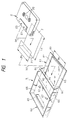
- Fig. 1 shows an embodiment of a storage case according to the invention in terms of a perspective view.
- the storage case 6 similarly to the conventional storage cases, includes a cover part 61 and a casing part 62 which is connected to the cover part in such a manner that it can be opened and closed.
- the cover part 61 includes a cover side opposing wall 63 to extend along one surface (in the illustrated embodiment, bottom surface) of a tape cassette 2, and a pocket 64 which is disposed at one end side of the cover side opposing wall 63 and also into which a front opening portion 21 formed in the tape cassette 2 can be inserted. That is, as shown in Fig. 1, an index card 7 and tape cassette 2 can be inserted along the cover side opposing wall 63 into the pocket 64.
- the casing part 62 includes a casing side opposing wall 65 for covering the other surface (in the illustrated embodiment, top surface) of the tape cassette 2 loaded on the cover part 61, a pivotally mounting portion 66 for connecting the casing side opposing wall 65 to the cover part 61 rotatably, and a pair of rotation preventive projections 67 provided projectingly on the casing side opposing wall 65.
- a shaft-like projection fittable into one of bearing holes respectively formed in the two side walls of the pocket 64 of the cover part 61 is projectingly provided at the corresponding position of the inner wall of the casing part 62, whereby the cover part 61 and casing part 62 are connected to each other in such a manner that they can be rotated mutually to each other.
- the rotation preventive projections 67 when the casing part 62 is rotated about the pivotally mounting portion 66 and thus the casing side opposing wall 65 is closed with respect to the cove plate 61, the projections 67 are engaged with hubs 22 provided in the tape cassette 2 loaded on the cover part 61 to prevent the tape from being loosened in the keeping of the tape.
- the positions of the rotation preventive projections 67 on the casing side opposing walls 65 are set so that the rotation preventive projections 67 can be surely engaged with the hubs 22 of the tape cassette 2 loaded on the cover part 61 whether the tape cassette 2 is loaded forwardly or reversely into the cover part 61.
- each of the rotation preventive projections 67 is so set as to have a shape like a flat plate which extends along the long side direction of the tape cassette 2.
- the positions of the hubs 22 to be engaged by the rotation preventive projections 67 are shifted according to the forward and reverse loading of the tape cassette 2 (in Fig. 2, the tape cassette 2 when it is loaded forwardly is shown by one-dot chained lines, while the tape cassette 2 when it is loaded reversely is shown by broken lines).
- the positions of the hubs 22 when the tape cassette 2 is loaded forwardly share areas 24, as shown by oblique lines in Fig. 2, in common with the positions of the hubs 22 when the tape cassette 2 is loaded reversely.
- the positions on the casing side opposing wall 65 corresponding to the common areas 24 are the positions in which the rotation preventive projections 67 are provided.
- recessed portions 81, 82, and 83 respectively for receiving the increased thickness portion 23 of the tape cassette 2 in order to allow both forward and reverse loading of the tape cassette 2 into the cover part 61.
- the recessed portion 82 formed in the pocket 64 is arranged to receive the increased thickness portion 23 when the front opening portion 21 is inserted into the pocket 64, that is, when the tape cassette 2 is loaded forwardly.
- the recessed portion 83 formed in the casing side opposing wall 65 is arranged to receive the increased thickness portion 23 when the rear end side of the tape cassette 2 is inserted into the pocket 64 (that is, when the front opening portion 21 is located at the opening end side of the storage case), or, in the reverse loading of the tape cassette 2.
- the recessed portion 81 formed in the cover side opposing wall 63 is formed in a single rectangular recessed portion which is an integrated portion consisting of a forward loading recessed portion for receiving the increased thickness portion 23 in the forward loading and a reverse loading recessed portion for receiving the increased thickness portion 23 in the reverse loading.
- the width dimensions W5 and W6 of the two recessed portions 81 and 82 are equal to each other.
- the index card 7 is arranged such that the width dimension W7 thereof is slightly smaller, 0.01-0.5mm smaller, for example, than the width dimension W5 of the recessed portion 81 and the length dimension L2 extending along the cover side opposing wall 63 is slightly smaller than the length dimension L3 (see Fig. 3) of the recessed portion 81.
- the recessed portion 81 formed in a rectangular recessed portion serves also as a card storage portion which stores the index card 7 therein and secures the end edge of the index card 7 by means of a stepped portion 85 provided in the edge of the recessed portion.
- arrows (c) and (d) respectively show the direction of insertion of the index card 7 into the cover part 61 and the direction of insertion of the tape cassette 2 into the cover part 61.
- FIG. 3 shows a state before the tape cassette 2 is inserted into the pocket 64 with the index card 7 mounted therein
- Fig. 4 shows a state in which the increased thickness portion 23 of the tape cassette 2 is inserted in the pocket 64.
- the width dimension W7 of the index card 7 is smaller than the width dimension W2 of the tape cassette 2, as shown in Fig. 5 as well, when the index card 7 is mounted in the cover part 61, there are left areas 68 in which the index card 7 is not present (which areas will hereinafter be referred to as space areas), on both sides of a title portion 71 of the index card 7.
- the cover part 61 is ordinarily formed of transparent plastic so that the description contents of the index card can be visually understood with ease from outside the case.
- engravings 69 are provided on the case inner surface corresponding to the space areas 68 so that the space areas 68 can be matched to the title portion 71 in the case in terms of design.
- Fig. 7 there is shown a method of enforcing a working operation such as the engravings 69 on the space areas 68.
- a working operation such as the engravings 69 on the space areas 68.
- a slide core 9 which is used in a forming and working step.
- the working on the inner surfaces of the space areas 68 may include opaquing working such as opaquing the space areas with fleckles and, besides, as shown in Fig. 8, characters such as TITLE can be engraved on the space areas 68.
- the recessed portions 81, 82 and 83 for receiving the increased thickness portion 23 of the tape cassette 2 are respectively formed in the cover side opposing wall 63, pocket 64 and casing side opposing wall 65, the projecting portion of the increased thickness portion 23 of the tape cassette 2 can be absorbed within the plate thickness dimensions of the cover side and casing side opposing walls 63, 65 and the like and thus, as the whole storage case, the thickness dimension thereof can be reduced, that is, the storage case can be made into a thinner shape.
- the thinner shape can reduce its keeping space and also can improve its portability.
- the recessed portions 81, 82 and 83 respectively formed in the cover part 61 and casing part 62 as well as the rotation preventive projections 67 are arranged in such a manner that they can be adapted to both forward and reverse loading of the tape cassette 2, the tape cassette can be inserted both forwardly and reversely. This eliminates an inconvenience that the tape cassette must be loaded again when it has been loaded from the wrong side. That is, the present structure allows the tape cassette to be loaded quite freely.
- the recessed portion 81 formed in the cover side opposing wall 63 is formed in a single rectangular recessed portion which is an integrated portion consisting of the forward loading recessed portion for receiving the increased thickness portion in the forward loading of the tape cassette and the reverse loading recessed portion for receiving the increased thickness portion in the reverse loading.
- the recessed portion 81 serves also as a card storage portion which not only stores the index card 7 but also secures the end edge of the index card 7 by means of the stepped portion 85 provided in the edge of the recessed portion 81. This structure can prevent the index card 7 from slipping off when the tape cassette 2 is taken out, and also can prevent generation of unnatural wrinkles and uneven surface portions in the index card 7, thereby being able to improve the handling property and commercial value of the case.
- any of the recessed portions 81, 82 and 83 does not reach the corners of the storage case, the strength of the case corners, which has an important significance on the drop speed of the storage case, is prevented from lowering in spite of the fact that the case is made thinner due to formation of the recessed portions.
- FIG. 9 there is shown another embodiment of a storage case according to the invention. That is, in Fig. 9, there is shown a storage case 10 into which the tape cassette 2 can be loaded vertically.
- the storage case 10 is similar in basic structure to the previously described embodiment. That is, the storage case 10 includes a cover part 101 and a casing part 102 which is connected to the cover part 101 openably and closably. And the cover part 101 includes a cover side opposing wall 103 to extend along one surface of the tape cassette and thus the index card 7 and tape cassette can be inserted into and removed from the storage case along the cover side opposing wall 103.
- the casing part 102 includes a casing side opposing wall 105 for covering the other surface of the tape cassette loaded on the cover part 101, a pivotally mounting portion 106 for connecting the casing side opposing wall 105 to the cover part 101 rotatably, and a pair of rotation preventive projections 107 which are respectively provided on the casing side opposing wall 105 and are engageable with hubs provided in the tape cassette loaded on the cover part 101 when the casing side opposing wall 105 is rotated about the pivotally mounting portion 106 and is closed with respect to the cover part 101.
- the projection positions of the rotation preventive projections 107 on the casing side opposing wall 105 are set such that the rotation preventive projections 10 are engageable with the hubs of the tape cassette loaded on the cover part 101 in both cases when the tape cassette is loaded onto the cover part 101 forwardly and reversely.
- recessed portions 111, 121, 122 for receiving the increased thickness portion of the tape cassette in order to allow the tape cassette to be loaded onto the cover part 101 not only forwardly but also reversely.
- the recessed portion 111 formed in the cover side opposing wall 103 is formed in a single rectangular recessed portion which can be formed by integrating a forward loading recessed portion 112 for receiving the increased thickness portion of the tape cassette in the forward loading and a reverse loading recessed portion 113 for receiving the increased thickness portion in the reverse loading into a united portion.
- the recessed portion 111 serves also as a card storage portion which not only stores the index card 7 but also secures the end edge of the index card 7 by means of a stepped portion 114 provided in the edge of the recessed portion 111.
- An arrow (e) shown in Fig. 9 designates the insertion direction of the index card 7 into the cover part 101.
- the cover side opposing wall 103 is long vertically.
- two side walls 108 are provided on both sides of the cover side opposing walls 103.
- the width dimension W7 of the index card 7 is set slightly smaller than the width dimension W8 of the recessed portion 111 in the cover side opposing wall 103. Also, similarly to the previously described embodiment, when the index card 7 is loaded on the cover part 101, not only the title portion 71 of the index card 7 is in contact with the front wall 130 of a pocket formed in the cover part 101 but also the end edge 72 of the index card 7 is secured to the stepped portion 114 of the recessed portion 111; and the securing of the end edge 72 of the index card 7 by the stepped portion 114 prevents the removal of the index card 7.
- the reduction in the case thickness can reduce its keeping space and can improve its portability.
- the structure of the present embodiment can prevent removal of the index card 7. Further, unnatural wrinkles and uneven surface portions are difficult to occur in the index card 7.
- the present embodiment allows the tape cassette to be inserted not only forwardly but also reversely and is thus improved in its handling property.
- a cover side opposing wall and a casing side opposing wall respectively include recessed portions for receiving the increased thickness portion of the magnetic tape cassette
- the projecting portion of the increased thickness portion of the tape cassette can be absorbed within the plate thickness dimensions of the cover side and casing side opposing walls and, thus, as the whole storage case, the thickness dimension thereof can be reduced considerably to provide a thinner storage case; and such reduction of the thickness can reduce its keeping space as well as can improve its portability.
- the recessed portions formed in the cover and casing parts as well as rotation preventive projections provided in the casing part are so arranged as to allow the magnetic tape cassette to be loaded not only forwardly but also reversely, the magnetic tape cassette can be inserted not only forwardly but also reversely, which eliminates an inconvenience that the magnetic tape cassette must be inserted again when it has been inserted in a wrong way.
- the recessed portion formed in the cover side opposing wall is formed in an integrated recessed portion consisting of a forward loading recessed portion for receiving the increased thickness portion of the tape cassette in the forward loading and a reverse loading recessed portion for receiving the increased thickness portion in the reverse loading, and the recessed portion serves also as a card storage portion which not only stores the index card but also secures the end edge of the index card by means of a stepped portion provided in the edge of the recessed portion.
- This structure can prevent the index card from being removed from the storage case when the tape cassette is taken out as well as can prevent unnatural wrinkles or uneven surface portions from occurring in the index card, thereby being able to improve the handling property and commercial value of the storage case.
Landscapes
- Packaging Of Annular Or Rod-Shaped Articles, Wearing Apparel, Cassettes, Or The Like (AREA)
Applications Claiming Priority (3)
| Application Number | Priority Date | Filing Date | Title |
|---|---|---|---|
| JP1993060280U JP2597474Y2 (ja) | 1993-10-14 | 1993-10-14 | 磁気テープカセット用ケース |
| JP6028093U | 1993-10-14 | ||
| JP60280/93U | 1993-10-14 |
Publications (3)
| Publication Number | Publication Date |
|---|---|
| EP0649141A2 true EP0649141A2 (de) | 1995-04-19 |
| EP0649141A3 EP0649141A3 (en) | 1995-05-17 |
| EP0649141B1 EP0649141B1 (de) | 1999-09-15 |
Family
ID=13137584
Family Applications (1)
| Application Number | Title | Priority Date | Filing Date |
|---|---|---|---|
| EP94116092A Expired - Lifetime EP0649141B1 (de) | 1993-10-14 | 1994-10-12 | Behälter für Magnetbandkassette |
Country Status (4)
| Country | Link |
|---|---|
| US (1) | US5518116A (de) |
| EP (1) | EP0649141B1 (de) |
| JP (1) | JP2597474Y2 (de) |
| DE (1) | DE69420660T2 (de) |
Families Citing this family (9)
| Publication number | Priority date | Publication date | Assignee | Title |
|---|---|---|---|---|
| EP0661703B1 (de) * | 1993-12-28 | 1998-04-01 | Fuji Photo Film Co., Ltd. | Kassettenbehälter |
| US5823353A (en) * | 1996-01-26 | 1998-10-20 | Perrin Manufacturing Company | Combination business card case and display case |
| EP1267350A3 (de) | 1996-08-23 | 2009-04-01 | FUJIFILM Corporation | Indexkarte für Plattenkassettenaufbewahrung |
| JP2000025874A (ja) * | 1998-07-09 | 2000-01-25 | Sony Corp | カセット収納ケース |
| JP2000025873A (ja) | 1998-07-09 | 2000-01-25 | Sony Corp | カセット収納ケース |
| JP2000025875A (ja) * | 1998-07-09 | 2000-01-25 | Sony Corp | カセット収納ケース |
| US6374648B1 (en) * | 1999-06-21 | 2002-04-23 | Masuhiro Mitsuyama | Commodity antitheft implement |
| JP2002234589A (ja) * | 2001-02-07 | 2002-08-20 | Fuji Photo Film Co Ltd | 磁気テープカセット用収納ケース |
| FR2843842B1 (fr) * | 2002-08-26 | 2007-02-23 | Valeo Equip Electr Moteur | Dispositif de commande d'une machine electrique tournante pour vehicule |
Family Cites Families (12)
| Publication number | Priority date | Publication date | Assignee | Title |
|---|---|---|---|---|
| GB2129779B (en) * | 1979-11-30 | 1984-10-31 | Peter Pendrill | Cases for recording media |
| DE3231041C2 (de) * | 1981-08-21 | 1987-03-12 | Victor Company Of Japan, Ltd., Yokohama, Kanagawa | Aufbewahrungsbehälter für eine Kassette |
| US4895252A (en) * | 1987-12-18 | 1990-01-23 | Laservideo, Inc. | Optical disc package |
| US5186325A (en) * | 1990-01-31 | 1993-02-16 | Sony Corporation | Cassette case and index sheet |
| US5154287A (en) * | 1991-01-10 | 1992-10-13 | Fuji Photo Film Co., Ltd. | Cassette accommodating case |
| US5160028A (en) * | 1991-01-10 | 1992-11-03 | Fuji Photo Film Co., Ltd. | Magnetic tape cassette accommodating case |
| JP2547726Y2 (ja) * | 1991-07-19 | 1997-09-17 | 富士写真フイルム株式会社 | 磁気テープカセット用収納ケース |
| US5168991A (en) * | 1991-10-08 | 1992-12-08 | Himont Incorporated | Compact disc package with moveable carrier |
| JPH0535783U (ja) * | 1991-10-15 | 1993-05-14 | 富士写真フイルム株式会社 | 磁気テープカセツト用収納ケース |
| JP2571079Y2 (ja) * | 1992-10-16 | 1998-05-13 | 富士写真フイルム株式会社 | 磁気テープカセット用収納ケース |
| US5284243A (en) * | 1992-10-21 | 1994-02-08 | Lakewood Industries, Inc. | Insertable tray for providing a multiple disc container |
| US5341926A (en) * | 1993-08-30 | 1994-08-30 | Leben David G | Container for carrying and transporting computer tape cartridges |
-
1993
- 1993-10-14 JP JP1993060280U patent/JP2597474Y2/ja not_active Expired - Fee Related
-
1994
- 1994-10-12 DE DE69420660T patent/DE69420660T2/de not_active Expired - Lifetime
- 1994-10-12 EP EP94116092A patent/EP0649141B1/de not_active Expired - Lifetime
- 1994-10-13 US US08/322,148 patent/US5518116A/en not_active Expired - Lifetime
Also Published As
| Publication number | Publication date |
|---|---|
| JPH0724792U (ja) | 1995-05-12 |
| JP2597474Y2 (ja) | 1999-07-05 |
| DE69420660T2 (de) | 2000-03-09 |
| EP0649141A3 (en) | 1995-05-17 |
| US5518116A (en) | 1996-05-21 |
| EP0649141B1 (de) | 1999-09-15 |
| DE69420660D1 (de) | 1999-10-21 |
Similar Documents
| Publication | Publication Date | Title |
|---|---|---|
| US5518116A (en) | Case for a magnetic tape cassette | |
| CA1224265A (en) | Magnetic tape cassette | |
| JPS6333830Y2 (de) | ||
| US4648507A (en) | Magnetic tape cassette storage case | |
| US5944182A (en) | Case for packaging and storing a magnetic disk cartridge | |
| EP0649142B1 (de) | Behälter für Magnetbandkassette | |
| US5899330A (en) | Encasing mechanism for a cassette enclosing a magnetic record medium | |
| US5429237A (en) | Magnetic tape cassette storing case | |
| EP0415083B1 (de) | Kassettenbehälter | |
| US5042659A (en) | Case for magnetic tape cassette | |
| EP0592887B1 (de) | Behälter für Magnetbandkassette | |
| EP0537678B1 (de) | Magnetbandkassettenbehälter | |
| US5450960A (en) | Cassette containing case with an index card | |
| US5381893A (en) | Housing case for tape cassette with index card | |
| JP2558808Y2 (ja) | 磁気テープカセット収納ケース | |
| JPS6014714Y2 (ja) | カセツトケ−ス | |
| JP2000159286A (ja) | 磁気テープカセット収納ケース | |
| US5707022A (en) | Cassette case for containing magnetic tape | |
| JP2723049B2 (ja) | カセット収納ケース | |
| JPH0617756Y2 (ja) | カセット収納ケース | |
| JP2538720Y2 (ja) | カセットハーフの収納ケース | |
| JPH082155Y2 (ja) | カセット収納ケース | |
| JPH0743823Y2 (ja) | テープカセット | |
| JPH0535507Y2 (de) | ||
| JP2589323Y2 (ja) | テープカセット収納ケース |
Legal Events
| Date | Code | Title | Description |
|---|---|---|---|
| PUAI | Public reference made under article 153(3) epc to a published international application that has entered the european phase |
Free format text: ORIGINAL CODE: 0009012 |
|
| PUAL | Search report despatched |
Free format text: ORIGINAL CODE: 0009013 |
|
| AK | Designated contracting states |
Kind code of ref document: A2 Designated state(s): DE FR |
|
| AK | Designated contracting states |
Kind code of ref document: A3 Designated state(s): DE FR |
|
| 17P | Request for examination filed |
Effective date: 19950828 |
|
| 17Q | First examination report despatched |
Effective date: 19980430 |
|
| GRAG | Despatch of communication of intention to grant |
Free format text: ORIGINAL CODE: EPIDOS AGRA |
|
| GRAG | Despatch of communication of intention to grant |
Free format text: ORIGINAL CODE: EPIDOS AGRA |
|
| GRAH | Despatch of communication of intention to grant a patent |
Free format text: ORIGINAL CODE: EPIDOS IGRA |
|
| GRAH | Despatch of communication of intention to grant a patent |
Free format text: ORIGINAL CODE: EPIDOS IGRA |
|
| GRAA | (expected) grant |
Free format text: ORIGINAL CODE: 0009210 |
|
| AK | Designated contracting states |
Kind code of ref document: B1 Designated state(s): DE FR |
|
| REF | Corresponds to: |
Ref document number: 69420660 Country of ref document: DE Date of ref document: 19991021 |
|
| ET | Fr: translation filed | ||
| PLBE | No opposition filed within time limit |
Free format text: ORIGINAL CODE: 0009261 |
|
| STAA | Information on the status of an ep patent application or granted ep patent |
Free format text: STATUS: NO OPPOSITION FILED WITHIN TIME LIMIT |
|
| 26N | No opposition filed | ||
| REG | Reference to a national code |
Ref country code: FR Ref legal event code: TP Ref country code: FR Ref legal event code: CD |
|
| PGFP | Annual fee paid to national office [announced via postgrant information from national office to epo] |
Ref country code: DE Payment date: 20090917 Year of fee payment: 16 |
|
| PGFP | Annual fee paid to national office [announced via postgrant information from national office to epo] |
Ref country code: FR Payment date: 20091102 Year of fee payment: 16 |
|
| PG25 | Lapsed in a contracting state [announced via postgrant information from national office to epo] |
Ref country code: FR Free format text: LAPSE BECAUSE OF NON-PAYMENT OF DUE FEES Effective date: 20101102 |
|
| REG | Reference to a national code |
Ref country code: FR Ref legal event code: ST Effective date: 20110630 |
|
| REG | Reference to a national code |
Ref country code: DE Ref legal event code: R119 Ref document number: 69420660 Country of ref document: DE Effective date: 20110502 |
|
| PG25 | Lapsed in a contracting state [announced via postgrant information from national office to epo] |
Ref country code: DE Free format text: LAPSE BECAUSE OF NON-PAYMENT OF DUE FEES Effective date: 20110502 |