EP0649224B1 - Codeur pour code de longueur variable et décodeur pour code de longueur variable - Google Patents
Codeur pour code de longueur variable et décodeur pour code de longueur variable Download PDFInfo
- Publication number
- EP0649224B1 EP0649224B1 EP94402089A EP94402089A EP0649224B1 EP 0649224 B1 EP0649224 B1 EP 0649224B1 EP 94402089 A EP94402089 A EP 94402089A EP 94402089 A EP94402089 A EP 94402089A EP 0649224 B1 EP0649224 B1 EP 0649224B1
- Authority
- EP
- European Patent Office
- Prior art keywords
- data
- codelength
- register
- signal
- outputting
- Prior art date
- Legal status (The legal status is an assumption and is not a legal conclusion. Google has not performed a legal analysis and makes no representation as to the accuracy of the status listed.)
- Expired - Lifetime
Links
- 230000004044 response Effects 0.000 claims description 43
- 101001091094 Homo sapiens Prorelaxin H1 Proteins 0.000 claims description 37
- 102100034945 Prorelaxin H1 Human genes 0.000 claims description 37
- 230000000873 masking effect Effects 0.000 description 27
- 238000010586 diagram Methods 0.000 description 14
- 238000010276 construction Methods 0.000 description 6
- 101100467813 Saccharomyces cerevisiae (strain ATCC 204508 / S288c) RBS1 gene Proteins 0.000 description 5
- 101150047356 dec-1 gene Proteins 0.000 description 4
- HCUOEKSZWPGJIM-YBRHCDHNSA-N (e,2e)-2-hydroxyimino-6-methoxy-4-methyl-5-nitrohex-3-enamide Chemical compound COCC([N+]([O-])=O)\C(C)=C\C(=N/O)\C(N)=O HCUOEKSZWPGJIM-YBRHCDHNSA-N 0.000 description 3
- 101001109689 Homo sapiens Nuclear receptor subfamily 4 group A member 3 Proteins 0.000 description 3
- 101000598778 Homo sapiens Protein OSCP1 Proteins 0.000 description 3
- 101001067395 Mus musculus Phospholipid scramblase 1 Proteins 0.000 description 3
- 102100022673 Nuclear receptor subfamily 4 group A member 3 Human genes 0.000 description 3
- 230000006870 function Effects 0.000 description 3
- 102100038026 DNA fragmentation factor subunit alpha Human genes 0.000 description 2
- 102100038023 DNA fragmentation factor subunit beta Human genes 0.000 description 2
- 101100028092 Drosophila melanogaster Or22a gene Proteins 0.000 description 2
- 101100277639 Homo sapiens DFFB gene Proteins 0.000 description 2
- 101000950906 Homo sapiens DNA fragmentation factor subunit alpha Proteins 0.000 description 2
- 230000003111 delayed effect Effects 0.000 description 2
- 238000005516 engineering process Methods 0.000 description 2
- 238000000034 method Methods 0.000 description 2
- 230000008569 process Effects 0.000 description 2
- 238000003491 array Methods 0.000 description 1
- 238000001514 detection method Methods 0.000 description 1
- 230000000694 effects Effects 0.000 description 1
- 230000004048 modification Effects 0.000 description 1
- 238000012986 modification Methods 0.000 description 1
Images


Classifications
-
- H—ELECTRICITY
- H03—ELECTRONIC CIRCUITRY
- H03M—CODING; DECODING; CODE CONVERSION IN GENERAL
- H03M7/00—Conversion of a code where information is represented by a given sequence or number of digits to a code where the same, similar or subset of information is represented by a different sequence or number of digits
- H03M7/30—Compression; Expansion; Suppression of unnecessary data, e.g. redundancy reduction
- H03M7/40—Conversion to or from variable length codes, e.g. Shannon-Fano code, Huffman code, Morse code
- H03M7/42—Conversion to or from variable length codes, e.g. Shannon-Fano code, Huffman code, Morse code using table look-up for the coding or decoding process, e.g. using read-only memory
Definitions
- the present invention relates in general to variable length decoders, and more particularly to a variable length decoder for performing variable length decoding for the entropy-coded video data from the variable length coder in real-time.
- variable length coding is adopted in the case where a data generation probability is not fixed. Namely, the variable length coding is used to represent data of the higher generation probability as a shorter code while data of the lower generation probability as a longer code.
- a Huffman code is well-known as the most effective entropy code.
- source coding is first performed for the digital video data to remove a data redundancy present in a signal source.
- the digital video data is then entropy-coded by run length coding and the variable length coding.
- variable length decoder the source-coded and entropy-coded data is decoded by a variable length decoder.
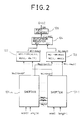
- the conventional variable length coder comprises a register 7 for storing temporarily data VLi inputted therein, a code generator 10 for generating a codeword VCW and a codelength VCL corresponding to output data from the register 7 and outputting the generated codeword VCW and codelength VCL to registers 8 and 9, respectively, and barrel shifters 5 and 6 for shifting an output codeword from the register 8 and an output codeword from a register 4.
- the register 4 is adapted to store temporarily an output codeword from the barrel shifter 6 and output the temporarily stored codeword to the barrel shifters 5 and 6.
- the conventional variable length coder comprises a register 3 for storing temporarily an output codeword from the barrel shifter 5 and outputting variable length-coded data VLCo, and a bit operation unit 1 for performing a logical operation for a reset signal RST and output data from a barrel shifter 2 to output an available data signal AVLC and apply bit information VL1 to the barrel shifters 2 and 5.
- the barrel shifter 2 is adapted to accumulate an output codelength from the register 9.
- the bit operation unit 1 includes a latch 14, flags 15-18, an OR gate OR1, a NOR gate NOR1 and an AND gate AN1.
- the code generator 10 is comprised of an uncoded-word table 11 of an AND-plane and a codeword table 12 and a codelength table 13 of OR-planes.
- the uncoded-word table 11, the codeword table 12 and the codelength table 13 are programmed logic arrays (PLAs), respectively.
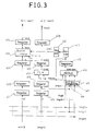
- the conventional variable length decoder comprises an interface circuit 609 for arranging and shifting data Vi compressed into a variable length code, inputted therein to designate a codeword to be decoded, and a decoding circuit 610 for comparing the designated codeword from the interface circuit 609 with codeword information stored therein, applying length information of the designated codeword from the interface circuit 609 to the interface circuit 609 in accordance with the compared result and outputting a decoded word V0-V3 corresponding to the designated codeword from the interface circuit 609 in accordance with the compared result.
- the interface circuit 609 includes a latch circuit 601 for inputting the data Vi through a buffer B1 and latching the inputted data Vi, a barrel shifter 602 for forming a 16-bit window I0-I15 according to output data VL0 and VL1 from the latch circuit 601, and an adder 606 for adding output data VL2 from a latch circuit 607 and a wordlength L0-L3 from the decoding circuit 610 and outputting the resultant data S0 to the latch circuit 607.
- the latch circuit 607 is adapted to latch the output data S0 from the adder 606 to output shift bit information to the barrel shifter 602 and latch a carry output C0 from the adder 606.
- the interface circuit 609 includes a read signal generator 608 for ANDing a clock signal CLK and a carry VL3 from the latch circuit 607 to generate a read signal RD and outputting the generated read signal RD to the buffer B1 and the latch circuit 601.
- the decoding circuit 610 includes a codeword storage unit 603 for storing information regarding an output codeword from the barrel shifter 602, a wordlength storage unit 604 for outputting the wordlength L0-L3 according to output data Cw from the codeword storage unit 603, and a decoded word storage unit 605 for outputting the decoded word V0-V3 through a latch L4 according to the output data Cw from the codeword storage unit 603.
- the codeword storage unit 603 is a PLA of an AND-plane
- the wordlength storage unit 604 and the decoded word storage unit 605 are PLAs of OR-planes.
- the register 7 In response to the clock signal CLK and an enable signal EN, the register 7 stores temporarily the inputted data VLi and then outputs it to the code generator 10.
- the codeword VCW and the codelength VCL corresponding to the output data from the register 7 are determined by the uncoded-word table 11, the codeword table 12 and the codelength table 13 in the code generator 10 and then applied to the registers 8 and 9, respectively.
- the codeword temporarily stored in the register 8 is applied to the barrel shifters 5 and 6 in response to the clock signal CLK and the enable signal EN.
- Each of the barrel shifters 5 and 6 employs a 16-bit sliding window for a 31-bit input.
- the barrel shifter 6 Upon receiving the current codelength from the register 9, the barrel shifter 6 shifts the codeword from the register 8 by the received codelength from the register 9 and outputs the shifted codeword to the register 4. In this case, a rightmost bit of the register 4 becomes a last data bit, thereby causing the data stored in the register 4 to be connected with the subsequently inputted data.
- the barrel shifter 5 is controlled by a remaining bits number of the latch 14.
- the latch 14 functions to store the number of the bits remaining in the register 4. Namely, the remaining bits number of the latch 14 represents the number of the bits of the codeword present in the register 4.
- the remaining bits of the register 4 are arranged on the basis of the left side by the barrel shifter 5. If the sum of the remaining bits number and the bits number of the current codeword is greater than or equal to 16, 16-bit data to be first coded is applied from the barrel shifter 5 to the register 3.
- the combination of the barrel shifter 2 and the latch 14 functions as an accumulator for accumulating a codelength.
- the number of the remaining bits in the register 4 is greater than or equal to 16
- the right 16 bits of the output data from the barrel shifter 2 become all 0 and the flag 15 is set to 1 indicative of presence of available data.
- the output data from the latch 14 is applied to the barrel shifter 2 to allow the barrel shifter 2 to function as a rotator.
- the other 16-bit input to the barrel shifter 2 is connected to "0" for searching for a carry-out condition. Namely, if the right 16 bits of the output data from the barrel shifter 2 are all "0", the carry-out occurs.
- the left 16 bits of the output data from the barrel shifter 2 represent the number of newly remaining bits in the register 4.
- the barrel shifter 6 Upon receiving the temporarily stored codelength from the register 9 in response to the clock signal CLK and the enable signal EN, the barrel shifter 6 shifts the inputted codeword by the received codelength and outputs the shifted codeword to the register 4.
- the barrel shifter 2 accumulates the codelength from the register 9 and outputs the accumulated value as shift information to the bit operation unit 1.
- the flags 18, 17 and 16 are set in response to the reset signal RST as the codeword is shifted in the above manner.
- the set flags 18, 17 and 16 are logically operated with the output data from the barrel shifter 2 by the OR gate OR1, the AND gate AN1 and the NOR gate NOR1, respectively.
- the output data from the OR gate OR1 and the AND gate AN1 are applied to the latch 14 and the output data from the NOR gate NOR1 is applied to the flag 15.
- the barrel shifter 5 upon receiving the bit information VL1 from the latch 14 as the available data signal AVLC of the flag 15 is set, the barrel shifter 5 outputs 16-bit variable length-coded data to the register 3. Also in this case, the accumulated codelength value of the barrel shifter 2 is cleared.
- the conventional variable length coder has the three barrel shifters connected in parallel.
- the use of the three barrel shifters connected in parallel makes the time required in coding a single word constant.
- the conventional variable length coder has the disadvantage that an operation speed is low in the case where a plurality of words are coded in parallel.
- the data stream Vi is inputted to the interface circuit 609.
- the buffer B1 applies the inputted data Vi to a latch L0 in the latch circuit 601 in the unit of 16 bits under the control of the read signal generator 608.
- the latch L0 shifts the existing data to a latch L1 of the latch circuit 601 and inputs the data Vi of new 16 bits.
- the latch circuit 601 outputs the latch data VL1 and VL0 of the respective 16 bits to the barrel shifter 602.
- the barrel shifter 602 Upon receiving the output data VL1 and VL0 from the latches L1 and L0 in the latch circuit 601, the barrel shifter 602 forms the window of bits I0-I15, a leading bit of which is the first bit to be decoded among the received 32 bits.
- the window from the barrel shifter 602 is shifted by the output data VL2 from the latch circuit 607, resulting in the detection of the codeword.
- the detected codeword is then applied to the codeword storage unit 603.
- the codeword storage unit 603 detects the decoded data Cw corresponding to the received codeword and then outputs it to the wordlength storage unit 604 and the decoded word storage unit 605.
- the wordlength storage unit 604 outputs the wordlength L0-L3 corresponding to the decoded data Cw from the codeword storage unit 603 to the adder 606.
- the decoded word storage unit 605 outputs the decoded word V0-V3 corresponding to the decoded data Cw from the codeword storage unit 603 through the latch L4.
- the adder 606 adds the output data L0-L3 from the wordlength storage unit 604 and the output data VL2 from the latch circuit 607 and outputs the added result as the bit shift information to a latch L2 in the latch circuit 607.
- the barrel shifter 602 forms the 16-bit window I0-I15 by shifting the output data VL1 and VL0 from the latch circuit 601 by the output data VL2 from the latch L2 in the latch circuit 607.
- a latch L3 of the latch circuit 607 outputs the carry VL3 to the read signal generator 608.
- an AND gate AN11 ANDs the clock signal CLK and the carry VL3 from the latch circuit 607 and outputs the ANDed result as the read signal RD to the buffer B1 and the latch L0 of the latch circuit 601.
- the buffer B1 outputs the data Vi of new 16 bits to the latch L0 of the latch circuit 601.
- Fig. 7 is a view illustrating an example of the wordlengths and codewords of the data used in the conventional variable length decoder of Fig. 6
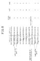
- Fig. 8 is a view illustrating an example of the decoding operation of the conventional variable length decoder of Fig. 6.
- the first 2 bits of the window of the barrel shifter 602 are recognized as a symbol b and applied to the codeword storage unit 603 in response to the first clock signal. Then, upon receiving the wordlength "2" from the wordlength storage unit 604, the adder 606 adds the received wordlength "2" to an initial value "0” and outputs the resultant value "2" to the latch L2. The output data "2" from the latch L2 causes the window of the barrel shifter 602 to be shifted by "2" to the right.
- the decoded word storage unit 605 outputs the decoded word V0-V3 corresponding to the codeword matched in the codeword storage unit 603.
- the subsequent 5 bits of the window of the barrel shifter 602 are recognized as a symbol g and applied to the codeword storage unit 603. Then, upon receiving the wordlength "5" from the wordlength storage unit 604, the adder 606 adds the received wordlength "5" to the previous value "2" and outputs the resultant value "7” to the latch L2. The output value "7" from the latch L2 causes the window of the barrel shifter 602 to be shifted by "7" to the right.
- the carry VL3 is generated in the latch L3 of the latch circuit 607 and applied to the read signal generator 608.
- the AND gate AN11 ANDs the clock signal CLK and the carry VL3 from the latch circuit 607 and outputs the ANDed result as the read signal RD to the buffer B1 and the latch L0 of the latch circuit 601.
- the buffer B1 outputs the data Vi of new 16 bits to the latch L0 of the latch circuit 601. Then, the above operation is repeatedly performed on the basis of the data Vi of the new 16 bits.
- the time required in the decoding is one cycle regardless of the length of the codeword, which is the sum of the delay time of the latch L0, the shifting delay time of the barrel shifter 602, the matching delay time of the codeword and the addition time of the adder 606.
- the conventional variable length decoder has the disadvantage that the decoding time is fixed regardless of the length of the codeword. Also, although the data is transmitted at a high bit rate, the operation of accumulating the length of the matched codeword may be delayed. This causes the decoding not to be performed in real-time.
- the present invention has been made in view of the above problems, and it is an object of the present invention to provide a variable length decoder for gaining simultaneous access to bits of the number to be shifted, when data is inputted to a code table, to perform a matching operation for bits other than designated bits, so as to remove shifting delay, and storing accumulated wordlength information to remove calculation delay in the matching operation, so that a decoding operation can be performed at a high speed in real-time.
- variable length decoder according to claim 1.
- variable length decoder according to claim 5.
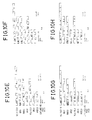
- variable length coder suitable for use with the present invention.
- the variable length coder comprises n shifters 101-1 to 101-n, each of which inputs a corresponding one of n codewords wordl-wordn and n codelengths lengthl-lengthn, shifts the corresponding codeword by a desired length for interconnection of the codewords and outputs masking bits designating a position of the corresponding codeword to be shifted.
- variable length coder comprises an OR gate 102 for ORing output codewords W1[1:16nx2]-Wn[1:16nx2] from then shifters 101-1 to 101-n, an OR gate 103 for ORing output masking bits M1[1:16nx2]-Mn[1:16nx2] from the n shifters 101-1 to 101-n, a word/mask register 104 for latching output codeword bits W[1:16nx2] from the OR gate 102 when corresponding output masking bits M[1:16nx2] from the OR gate 103 are enabled to "1", and a first-in-first-out (FIFO) memory 105 for storing an output C[1:16n] of the word/mask register 104 and outputting variable length-coded data DVLC.
- OR gate 102 for ORing output codewords W1[1:16nx2]-Wn[1:16nx2] from then shifters 101-1 to 101-n
- each of the codewords inputted to the shifters 101-1 to 101-n has the maximum length of 16 bits
- each of the codewords inputted to the shifters 101-1 to 101-n may have the maximum length greater than 16 bits.
- the shifters may process the inputted codewords in the unit of 16 bits.
- the number of the used shifters is n for performing the variable length coding at the high speed. For example, in the case where the number of the used shifters is 2, a codeword Wi[1:16nx2] means that a codeword outputted from the ith shifter 101-i has a length of a range of 1 to 64 bits.
- the ith shifter 101-i includes registers 401-403 for storing sequentially the ith codeword wordi, registers 404 and 405 for storing sequentially the ith codelength lengthi, an interface circuit 415 for inputting an output codelength from the register 404, and an adder 409 for adding output data from the interface circuit 415 and output data SUM(410) from a register 410.
- the register 410 is adapted to store output data from the adder 409 and output the stored data to a PLA 406, the adder 409 and a decoder 411.
- the PLA 406 is adapted to obtain the masking bits Mi[1:16nx2] by setting bits of the number corresponding to an output codelength from the register 405 to "1" and rotating the resultant bits by the output data SUM(410) from the register 410 and output the obtained masking bits Mi[1:16nx2] through registers 407 and 408.
- the decoder 411 is adapted to decode the output data SUM(410) from the register 410 and output the decoded data to a barrel rotator 413 through a register 412 to control a rotating size of the barrel rotator 413.
- the barrel rotator 413 is adapted to rotate an output codeword from the register 403 according to output data from the register 412 and output the rotated codeword Wi[1:16nx2] through a register 414.
- the interface circuit 415 is adapted to apply 1st to (i-1)th codelengths directly to the adder 409, whereas ith to nth codelengths through its registers to the adder 409.
- the barrel rotator 413 may be substituted with two barrel shifters.
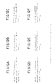
- the word/mask register 104 includes a latch circuit 501 being enabled in response to the masking bits M[1:16n] from the OR gate 103 to latch the masking bits M[1:16n] and the codeword bits W[1:16n] from the OR gate 102 synchronously with a clock signal CLK if i ⁇ 16n, and a latch circuit 502 being enabled in response to the masking bits M[16n+1:32n] from the OR gate 103 to latch the masking bits M[16n+1:32n] and the codeword bits W[16n+1:32n] from the OR gate 102 synchronously with the clock signal CLK if i > 16n.
- the word/mask register 104 includes a bit set state discriminator 503 for ANDing first output data bits FA[1:16n] from the latch circuit 501 and discriminating a masking bit set state in accordance with the ANDed result, a bit set state discriminator 504 for ANDing first output data bits FB[1:16n] from the latch circuit 502 and discriminating a masking bit set state in accordance with the ANDed result, a reset signal generator 505 for inputting output data from the bit set state discriminator 503 directly and through a flip-flop and ANDing the inputted data to output a reset signal RSTA to the latch circuit 501, a reset signal generator 506 for inputting output data from the bit set state discriminator 504 directly and through a flip-flop and ANDing the inputted data to output a reset signal RSTB to the latch circuit 502, a flag generator 507 for ORing the output data from the bit set state discriminators 503 and 504 and outputting the ORed result as an available code flag VCF through a
- the latch circuit 502 has the same construction as that of the latch circuit 501.
- variable length coder With the above-mentioned construction in accordance with the present invention will hereinafter be described in detail.
- the codewords word1-wordn and the codelengths lengthl-lengthn corresponding to the inputted data are applied to the shifters 101-1 to 101-n, respectively.
- the shifters 101-1 to 101-n calculates the positions of the corresponding codewords to be shifted, for the interconnection of the codewords with different lengths.
- the shifters 101-1 to 101-n then shift the corresponding codewords to the calculated positions.
- the ith codeword wordi is sequentially stored into the registers 401-403 and then applied to the barrel rotator 413.
- the ith codelength lengthi is applied to the register 405 and the interface circuit 415 through the register 404.
- the ith codelength lengthi is also applied to an interface circuit of a different shifter connected in parallel to the ith shifter 101-i.
- the interface circuit 415 applies the 1st to (i-1)th codelengths directly to the adder 409, whereas ith to nth codelengths lengthi-lengthn through its registers 416 and 417 to the adder 409 for time delay.
- the adder 409 accumulates the 1st to nth codelengths and outputs the accumulated value SUM(409) to the PLA 406 and the decoder 411 through the register 410.
- the output SUM(409) of the adder 409 is also fed back thereto through the register 410.
- the output SUM(409) of the adder 409 can be expressed by the following equation (1): In the above equation (1), lengthi is the codelength applied directly to the adder 409 and Lj is the codelength applied to the adder 409 through the registers 416 and 417.
- the barrel rotator 413 combines the codeword wordi sequentially delayed by the registers 401-403 with 16nx2-16 "0"s.
- the input of 16nx2-16 “0”s is for making up a difference between the bits number "16" of the input data and the bits number "16nx2" of the output data.
- the decoder 411 decodes the accumulated codelength value inputted through the register 410 to set bits of the number corresponding to the decoded value to "1". Then, the decoder 411 applies the resultant bits to the barrel rotator 413 through the register 412. The data of the barrel rotator 413 is shifted by the output data from the register 412.
- the barrel rotator 413 shifts the codeword by a size designated by the output data from the register 412, in a similar manner to the barrel shifter. But, noticeably, the barrel rotator 413 rotates a data portion being removed due to the shifting, to the opposite input. Namely, the data shifted to the left is again used as the right input.
- the codeword Wi[1:16nx2] rotated in this manner is applied to the OR gate 102 through the register 414.
- the delay time of the codeword wordi through the registers 401-403 to the barrel rotator 413 is the same as that of the codelength lengthi through the adder 409 and the decoder 411 to the barrel rotator 413.
- the PLA 406 sets bits of the number corresponding to the output codelength from the register 405 to "1" and rotates the resultant bits by the output data SUM(410) from the register 410, so as to determine a length and a relative position of the codeword.
- the output data from the PLA 406 is the masking bits Mi[1:16nx2], which are applied to the OR gate 103 through the registers 407 and 408. Bits set to "1" among the masking bits Mi[1:16nx2] represent the amount and position of an available code of the codeword Wi[1:16nx2] to be rotated.
- the OR gates 102 and 103 OR the shifted codewords Wi[1:16nx2] and the masking bits Mi[1:16nx2] from the shifters 101-1 to 101-n, respectively.
- Mn[I] W[I] W1[I]
- the flip-flops DFF1 and DFF2 are enabled if the masking bit M[1] is enabled to "1", thereby causing the codeword bit W[1] and the masking bit M[1] to be outputted therefrom synchronously with the clock signal CLK.
- the masking bit M[1] is disabled to "0"
- the previous state is maintained as it is. This operation is performed in the same manner by the latches in the latch circuits 501 and 502.
- the latch circuits 501 and 502 then outputs the codeword bits SA[1:16n] and SB[1:16n] and the masking bits FA[1:16n] and FB[1:16n], respectively.
- the masking bits FA[1:16n] and FB[1:16n] from the latch circuits 501 and 502 are applied to the bit set state discriminators 503 and 504, respectively.
- bit set state discriminators 503 and 504 the masking bits FA[1:16n] and FB[1:16n] from the latch circuits 501 and 502 are ANDed by AND gates, respectively. If the output of the bit set state discriminator 503 is "1", the flag generator 507 outputs the available code flag VCF of "1" through its OR gate and flip-flop F/F. In response to the output of the bit set state discriminator 503, the multiplexer 508 selects the output data bits SA[1:16n] of the latch circuit 501 and then applies them to the FIFO memory 105. Also in the reset signal generator 505, an AND gate inputs the output data from the bit set state discriminator 503 directly and through the flip-flop and ANDs the inputted data.
- the ANDed result from the AND gate is applied as the reset signal RSTA to the latch circuit 501.
- the flip-flops in the latch circuit 501 are cleared, thereby causing the output of the bit set state discriminator 503 to be disabled to "0".
- the flag generator 507 outputs the available code flag VCF of "1" through its OR gate and flip-flop F/F.
- the multiplexer 508 selects the output data bits SB[1:16n] of the latch circuit 502 and then applies them to the FIFO memory 105.
- an AND gate inputs the output data from the bit set state discriminator 504 directly and through the flip-flop and ANDs the inputted data. The ANDed result from the AND gate is applied as the reset signal RSTB to the latch circuit 502.
- the flip-flops in the latch circuit 502 are cleared, thereby causing the output of the bit set state discriminator 504 to be disabled to "0".
- the FIFO memory 105 stores the output data C[1:16n] from the word/mask register 104 and outputs the variable length-coded data DVLC.
- variable length coder suitable for use with the present invention
- dec1(i,j) is which means that is rotated by j to the right.
- decl(6, 10) means that bits rrom the left up to the sixth bit are rotated by 10 and then applied to the register 407.
- the subsequent operation of the second shifter is the same as that of the first shifter and a description thereof will thus be omitted.
- variable length coder employs such a parallel process that the words inputted at a time are shifted to the desired positions by the barrel rotators and then simultaneously coded by latching only the bits corresponding to the set state of the flag indicating the code presence position. Therefore, the present invention may be applied to encoders of a digital television, a high definition television (HDTV) and a digital video cassette recorder (DVCR) to code video signals at a high speed.
- HDTV high definition television
- DVCR digital video cassette recorder
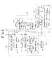
- variable length decoder of the present invention comprises a data shifter 700 for shifting input data Vi according to outputs of a decoding circuit 720 and a shift controller 730.
- the decoding circuit 720 is adapted to input output data RBS3 from the data shifter 700 and a previous codelength RLN1 from the shift controller 730, discriminate a matched state of the inputted data RBS3 on the basis of the previous codelength RLN1, generate a current codelength LN1, a matching signal MS1 and a decoded word VCD in accordance with the discriminated result and output the generated current codelength LN1 to the shift controller 730 and the generated matching signal MS1 to the shift controller 730 and the data shifter 700.
- the shift controller 730 is adapted to control a shifting amount of the data shifter 700 in response to the current codelength LN1 and the matching signal MS1 from the decoding circuit 720 and output the previous codelength RLN1 to the data shifter 700 and the decoding circuit 720.
- the data shifter 700 includes registers 711 and 712 for storing sequentially the input data Vi in response to a ready signal RDY from the shift controller 730, a barrel shifter 713 for shifting output data VL0 and VL1 from the registers 711 and 712 and the input data Vi by an accumulated codelength value RS0 from the shift controller 730, a register 714 for storing and outputting output data BS1 from the barrel shifter 713 in response to an available code signal VCF from the shift controller 730, a barrel shifter 715 for shifting output data RBS1 from the register 714 by the previous codelength RLN1 from the shift controller 730, a register 716 for storing and outputting output data BS2 from the barrel shifter 715 in response to the matching signal MS1 from the decoding circuit 720, a barrel shifter 717 for shifting output data VL3 from the register 716 and output data VL4 from a register 718 by the previous codelength RLN1 from the shift controller 730, and a register 719 for
- the shift controller 730 includes a register 731 for storing the current codelength LN1 from the decoding circuit 720 and outputting the stored codelength as the previous codelength RLN1 to the data shifter 700 and the decoding circuit 720, a flip-flop 732 for latching the matching signal MS1 from the decoding circuit 720 and outputting the latched signal as the available code signal VCF to the data shifter 700, an inverter 735 for inverting the available code signal VCF from the flip-flop 732, a register 733 for storing temporarily the accumulated codelength value RS0 in response to the available code signal VCF from the flip-flop 732, an adder 734 for adding the previous codelength RLN1 from the register 731 and output data RR5 from the register 733 and outputting the added value as the ready signal RDY and a sum signal S0, and a register 736 for storing the sum signal S0 from the adder 734 and outputting the stored signal as the accumulated codelength value RS0 to the data shifter 700
- the decoding circuit 720 includes a codelength storage unit 721 for matching the output data RBS3 from the data shifter 700 with data stored therein on the basis of the previous codelength RLN1 from the shift controller 730 and outputting the current codelength LN1 to the shift controller 730 in accordance with the matched result, a matching detector 722 for generating the matching signal MS1 according to the matching operation of the codelength storage unit 721 and outputting the generated matching signal MS1 to the data shifter 700 and the shift controller 730, a decoded word storage unit 723 for outputting a desired decoded word Vo according to the matching operation of the codelength storage unit 721, and a register 724 for storing the desired decoded word Vo from the decoded word storage unit 723 and outputting the decoded word VCD.
- a codelength storage unit 721 for matching the output data RBS3 from the data shifter 700 with data stored therein on the basis of the previous codelength RLN1 from the shift controller 730 and outputting the current codelength LN1
- variable length decoder With the above-mentioned construction in accordance with the embodiment of the present invention will hereinafter be described in detail with reference to Fig. 9.
- a maximum length of the code is 16 bits.
- the input data Vi is sequentially applied to the registers 711 and 712 and the barrel shifter 713.
- the barrel shifter 713 the input data Vi and the output data VL0 and VL1 from the registers 711 and 712 are shifted to the left by the accumulated codelength value RS0 from the shift controller 730 and then applied to the register 714.
- the output data RBS1 from the shifter 714 is applied to the barrel shifter 715 in response to the available code signal VCF from the shift controller 730.
- the output data RBS1 from the shifter 714 is shifted to the left by the previous codelength RLN1 from the shift controller 730 and then temporarily stored in the register 716.
- the output data BS2 from the barrel shifter 715 stored in the register 716 is applied to the barrel shifter 717 in response to the matching signal MS1 from the decoding circuit 720.
- the output data VL3 from the register 716 is shifted to the left by the previous codelength RLN1 from the shift controller 730.
- the output data BS3 from the barrel shifter 717 is fed back thereto through the register 718 and applied to the register 719. Then, the output data RBS3 from the register 719 is applied to the decoding circuit 720.
- the output data RBS3 from the register 719 is matched with data in a codeword/codelength table of the codelength storage unit 721 on the basis of the previous codelength RLN1 from the shift controller 730.
- a codeword and the codelength LN1 are detected as a result of the matching operation of the codelength storage unit 721.
- the detected codeword from the codelength storage unit 721 is decoded by the decoded word storage unit 723 and then the resultant decoded word VLD is outputted through the register 724.
- the detected codelength LN1 from the codelength storage unit 721 is applied to the register 731 in the shift controller 730.
- the matching detector 722 discriminates whether the output data RBS3 from the register 719 is matched within 16 bits.
- the decoding circuit 720 includes a PLA comprised of broken flag data.
- the flag data contains flag information indicating whether the output data RBS3 from the register 719 is a code within 16 bits.
- the output data RBS3 from the register 719 is shifted to the left in the decoding circuit 720 in such a manner that the previous data bits are stored as high-order bits and new data bits are stored as low-order bits.
- the decoding circuit 720 Upon receiving the output data RBS3 from the register 719 together with a 5-bit output or the previous codelength RLN1 from the shift controller 730, the decoding circuit 720 excepts the high-order bits of the number corresponding to the previous codelength RLN1 from the data RBS3 and performs the matching operation beginning with the highest-order bit of the remaining bits.
- the codelength and decoded word matched in this manner are applied to the registers 731 and 724, respectively.
- the matching signal MS1 is "1" this means that the matching is established.
- the matching signal MS1 is "0"
- the matching signal MS1 from the decoding circuit 720 is latched by the flip-flop 732 and then outputted as the available code signal VCF therefrom, so as to indicate that the data stored in the register 724 is a normally decoded word.
- the available code signal VCF from the flip-flop 732 is inverted by the inverter 735 and then applied as a latch enable signal to the register 736, thereby causing the register 736 to latch the output of the adder 734.
- the previous codelength RLN1 from the register 731 is added to the matched codelength of the output data RBS3 from the data shifter 700 and the added value is fed as the current codelength LN1 back to the register 731.
- the resultant previous codelength RLN1 from the register 731 is then applied to the barrel shifters 715 and 717 in the data shifter 700, which thus shift the data to the left by the resultant previous codelength RLN1.
- the matching signal MS1 from the decoding circuit 720 is set to the broken flag, the values of the registers 714,716,718 and 719 in the data shifter 700 are updated into new values and the value of the register 733 in the shift controller 730 is updated after one clock.
- the adder 734 adds the output data RLN1 and RR5 from the registers 731 and 733 and outputs the added data to the register 736 and the registers 711 and 712 in the data shifter 700. At this time, the register 736 inputs the output of the adder 734 when being enabled by the output of the inverter 735.
- a carry may be generated in the adder 734 and then outputted as the ready signal RDY therefrom.
- the ready signal RDY indicates that the devices are ready to input the next data.
- new data Vi is stored into the registers 711 and 712 in the data shifter 700 in response to the next clock signal.
- the registers 711, 712, 714, 716, 718, 719, 724, 731, 733 and 736 and the flip-flop 732 are operated in response to the same clock signal.
- each of the input data Vi, the output data of the registers 719,711,712,716 and 718 and the output data of the decoded word storage unit 723 and the output data of the barrel shifters 717 and 715 may be m bits and each of the output data of the barrel shifter 713 and the register 714 may be 2m bits.
- each of the output data RLN1 and LN1 of the register 731 and the codelength storage unit 721 may be (L + 1) bits, in which L + 1 is an integer and L ⁇ log2m.
- each of the output data RS0, RR5 and S0 of the registers 736 and 733 and the adder 734 may be L bits.
- the decoding circuit 720 performs the decoding operation for the m-bit output data RBS3 from the register 719 beginning with the highest-order bit thereof.
- the decoding circuit 720 reads a length of the first code of the m-bit output data RBS3 from the register 719 and outputs the read codelength to the register 731, which then feeds the stored codelength RLN1 back to the decoding circuit 720.
- the decoding circuit 720 reads a length of the second code of the m-bit output data RBS3 from the register 719. The read length of the second code is added to the first codelength and the added value is applied to the register 731.
- the above feedback operation is continuously performed until the broken flag is generated in the decoding circuit 720.
- the codes of the m-bit output data RBS3 from the register 719 are all decoded by repeatedly performing the above feedback operation until the broken flag is generated in the decoding circuit 720. Therefore, the time as much as a codetable matching cycle is required in decoding one code. This makes the high-speed decoding possible.
- the register 731 is reset to "0" in response to the matching signal MS1 and the reset value thereof is applied to the decoding circuit 720 together with the arranged data RBS3 from the register 719.
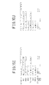
- variable length decoder in accordance with the embodiment of the present invention will hereinafter be described in more detail with reference to a data flowchart of Fig. 10.
- the data VL1, VL0, Vi, BS1 and RBS1 have no variation because of the absence of the ready signal RDY, the data RS0 and the available code signal.
- the data LN1 Since the matching is not established due to the broken state of the subsequent data B from the register 719, the data LN1 becomes a don't care state of XXXX.
- the matching signal MS1 becomes 1 because the matching is established for 10 bits of the first data A from the register 719.
- the data Vo becomes a don't care state of X resulting from the don't care state of the data LN1.
- the matched first data A appears at the data VCD.
- the data VL1, VL0 and Vi have still no variation because of no generation of the ready signal RDY.
- the data RBS1 has still no variation.
- a length (01000) of the data B appears at the data LN1.
- the matching signal MS1 becomes 0 because no matching is established.
- the data B appears at the data Vo.
- the value X of the data Vo at the moment t
- the above operation is repeatedly performed in such a manner that one data is decoded every two clock signals when its length is long, whereas every one clock when its length is short.
- the variable length decoder comprises a data shifter 801 for shifting input data Vi in response to a ready signal RDY, and a decoding circuit 810 for detecting a current codelength LN1 from output data BS1 from the data shifter 801 on the basis of a previous codelength RLN1, outputting a most significant bit of the detected current codelength LN1 as the ready signal RDY to the data shifter 801 and decoding the output data BS1 from the data shifter 801 on the basis of the previous codelength RLN1 to output a decoded word VCD.
- the data shifter 801 includes registers 802 and 803 for storing sequentially the input data Vi in response to the ready signal RDY from the decoding circuit 810, and a register 804 for storing output data VL0 and VL1 from the registers 802 and 803 in response to the ready signal RDY from the decoding circuit 810 and outputting the stored data to the decoding circuit 810.
- the decoding circuit 810 includes a codeword/codelength storage unit 811 for matching the output data BS1 from the data shifter 801 with data stored therein on the basis of the previous codelength RLN1, adding a matched codelength to the previous codelength RLN1 and outputting the added value as the current codelength LN1, a decoded word storage unit 813 for outputting a desired decoded word Vo according to the matching operation of the codeword/codelength storage unit 811, a register 814 for storing the desired decoded word Vo from the decoded word storage unit 813 and outputting the decoded word VCD, and a register 812 for storing the current codelength LN1 from the codeword/codelength storage unit 811 and feeding the stored codelength as the previous codelength RLN1 back to the codeword/codelength storage unit 811.
- variable length decoder With the above-mentioned construction in accordance with the alternative embodiment of the present invention will hereinafter be described in detail with reference to Fig. 11.
- the input data Vi is stored into the register 802 in the unit of 16 bits and then loaded into the register 803 in response to the next clock signal. Then, new input data is applied to the register 802.
- the output data VL0 and VL1 from the registers 802 and 803 are temporarily stored into the register 804 and then applied as the 32-bit code data BS1 to the decoding circuit 810.
- the output data BS1 from the register 804 in the data shifter 801 and the previous codelength RLN1 from the register 812 are applied to the codeword/codelength storage unit 811.
- the codeword/codelength storage unit 811 excepts high-order bits of the number corresponding to the previous codelength RLN1 from the data BS1 and performs the matching operation beginning with the highest-order bit of the remaining bits.
- the matched codelength is added to the previous codelength RLN1 from the register 812 and the added value is applied as the current codelength LN1 to the register 812.
- the decoded word storage unit 813 outputs the desired decoded word Vo to the register 814 according to the matching operation of the codeword/codelength storage unit 811.
- the output data LN1 from the codeword/codelength storage unit 811 and the output data Vo from the decoded word storage unit 813 are loaded into the registers 812 and 814 and outputted as the previous codelength RLN1 and the decoded word VCD therefrom in response to the clock signal, respectively.
- the output data RLN1 from the register 812 and the output data BS1 from the data shifter 801 are applied to the codeword/codelength storage unit 811 in response to the next clock signal. In this manner, the decoding operation is repeatedly performed.
- variable length decoder in accordance with the alternative embodiment of the present invention will hereinafter be described in more detail with reference to a data flowchart of Fig. 12.
- the data VL1, VL0 and BS1 have no variation because of the absence of the ready signal RDY.
- a codelength (0110) of data A appears at the data RLN1.
- the data LN1 becomes a value (01010) obtained by adding a codelength of data B to the codelength (0110) of the data A.
- the matched data B appears at the data Vo.
- the data VL1, VL0 and BS1 have still no variation because of no generation of the ready signal RDY. Namely, the ready signal RDY is not generated since a most significant bit of the data LN1 of "01010" is not "1".
- the data RLN1 of "1010” is added to a codelength (0100) of data C obtained by performing the matching operation for bits of the data BS1 except bits of the number corresponding to the data RLN1 of "1010", and then the added value (01110) appears at the data LN1.
- the matched data C appears at the data Vo.
- each of the output data VL0 and VL1 from the registers 802 and 803 is m bits and the output data BS1 from the register 804 is 2m bits.
- the output data LN1 from the codeword/codelength storage unit 811 is (L + 1) bits, where L ⁇ 2log2m.
- variable length decoder performs the matching operation for the remaining bits of the data except bits of the number corresponding to the previously decoded length. Therefore, in the decoding operation, there can be removed a delay time required in arranging the remaining bits beginning with the highest-order bit and performing the matching operation for the arranged bits. This has the effect of performing the decoding operation at a high speed.
Landscapes
- Engineering & Computer Science (AREA)
- Theoretical Computer Science (AREA)
- Compression, Expansion, Code Conversion, And Decoders (AREA)
Claims (7)
- Un décodeur pour code à longueur variable, comprenant :des moyens de décalage de données (700) qui décalent des données d'entrée (Vi) sous la dépendance d'une longueur de code précédente et d'un signal de concordance;des moyens de décodage (720) qui reçoivent en entrée des données de sortie provenant des moyens de décalage de données (700) et la longueur de code précédente (RLN1), qui effectuent une discrimination concernant un état concordant des données d'entrée, sur la base de la longueur de code précédente, qui génèrent une longueur de code courante (LN1), le signal de concordance (MS1) et un mot décodé (Vo) conformément au résultat de la discrimination, et qui émettent vers les moyens de décalage de données le signal de concordance qui est généré; etdes moyens de commande de décalage (730) qui commandent une valeur de décalage des moyens de décalage de données sous la dépendance de la longueur de code courante (LN1) et du signal de concordance (MS1) provenant des moyens de décodage, et qui émettent la longueur de code précédente (RLN1) vers les moyens de décalage de données et les moyens de décodage.
- Un décodeur pour code à longueur variable selon la revendication 1, dans lequel les moyens de décalage de données comprennent :des premier et second registres pour enregistrer séquentiellement les données d'entrée en réponse à un signal d'état prêt provenant des moyens de commande de décalage;un premier circuit de décalage circulaire pour décaler des données de sortie provenant des premier et second registres et les données d'entrée, d'une valeur de longueur de code accumulée provenant des moyens de commande de décalage;un troisième registre pour enregistrer et émettre des données provenant du premier circuit de décalage circulaire, en réponse à un signal de code disponible provenant des moyens de commande de décalage;un second circuit de décalage circulaire pour décaler des données de sortie du troisième registre de la longueur de code précédente provenant des moyens de commande de décalage;un quatrième registre pour enregistrer et émettre des données de sortie du second circuit de décalage circulaire, en réponse au signal de concordance provenant des moyens de décodage;un troisième circuit de décalage circulaire pour décaler des données de sortie du quatrième registre et des données de sortie d'un cinquième registre, de la longueur de code précédente provenant des moyens de commande de décalage, le cinquième registre enregistrant temporairement des données de sortie du troisième circuit de décalage circulaire et renvoyant les données enregistrées vers le troisième circuit de décalage circulaire en réponse au signal de concordance provenant des moyens de décodage; etun sixième registre pour émettre les données de sortie du troisième circuit de décalage circulaire vers les moyens de décodage, en réponse au signal de concordance provenant des moyens de décodage.
- Un décodeur pour code à longueur variable selon la revendication 1, dans lequel les moyens de décodage comprennent :une unité d'enregistrement de longueur de code pour rechercher une concordance entre les données de sortie des moyens de décalage de données et des données qui sont enregistrées dans cette unité, sur la base de la longueur de code précédente provenant des moyens de commande de décalage, et pour émettre la longueur de code courante vers les moyens de commande de décalage, conformément au résultat de concordance;un détecteur de concordance pour générer le signal de concordance conformément à l'opération de recherche de concordance de l'unité d'enregistrement de longueur de code, et pour émettre le signal de concordance généré vers les moyens de décalage de données et les moyens de commande de décalage;une unité d'enregistrement de mot décodé pour émettre le mot décodé conformément à l'opération de recherche de concordance de l'unité d'enregistrement de longueur de code; etun registre pour enregistrer le mot décodé provenant de l'unité d'enregistrement de mot décodé.
- Un décodeur pour code à longueur variable selon la revendication 1, dans lequel les moyens de commande de décalage comprennent:un premier registre pour enregistrer la longueur de code courante provenant des moyens de décodage et pour émettre la longueur de code enregistrée, pour la longueur de code précédente, vers les moyens de décalage de données et les moyens de décodage;une bascule pour mémoriser le signal de concordance provenant des moyens de décodage et pour émettre le signal mémorisé vers les moyens de décalage de données, sous la forme d'un signal de code disponible;un inverseur pour inverser le signal de code disponible provenant de la bascule;un second registre pour enregistrer temporairement une valeur de longueur de code accumulée, en réponse au signal de code disponible provenant de la bascule;un additionneur pour additionner la longueur de code précédente provenant du premier registre et des données de sortie provenant du second registre et pour émettre la valeur additionnée, sous la forme d'un signal d'état prêt et d'un signal de somme, le signal d'état prêt étant appliqué aux moyens de décalage de données; etun troisième registre pour enregistrer le signal de somme provenant de l'additionneur et pour émettre le signal enregistré, pour la valeur de longueur de code accumulée, vers les moyens de décalage de données et le second registre, en réponse à un signal de sortie de l'inverseur.
- Un décodeur pour code à longueur variable, comprenant :des moyens de décalage de données (700) pour décaler des données d'entrée en réponse à un signal d'état prêt (RDY); etdes moyens de décodage (720) pour détecter une longueur de code courante (LN1) dans les données qui sont émises par les moyens de décalage, sur la base d'une longueur de code précédente, les moyens de décodage effectuant en outre les opérations qui consistent à émettre le bit le plus significatif de la longueur de code courante détectée, pour le signal d'état prêt, vers les moyens de décalage de données, et à décoder les données de sortie des moyens de décalage de données, sur la base de la longueur de code précédente, pour émettre un mot décodé.
- Un décodeur pour code à longueur variable selon la revendication 5, dans lequel les moyens de décalage de données comprennent :des premier et second registres pour enregistrer séquentiellement les données d'entrée en réponse à un signal d'état prêt provenant des moyens de décodage; etun troisième registre pour décaler les données de sortie des premier et second registres en réponse au signal d'état prêt provenant des moyens de décodage, et pour émettre les données décalées vers les moyens de décodage.
- Un décodeur pour code à longueur variable selon la revendication 5, dans lequel les moyens de décodage comprennent :une unité d'enregistrement de mot de code / longueur de code pour rechercher une concordance entre les données de sortie des moyens de décalage de données et des données qui sont enregistrées dans cette unité, sur la base de la longueur de code précédente, pour additionner une longueur de code concordante à la longueur de code précédente et pour émettre la valeur additionnée pour la valeur de code courante;une unité d'enregistrement de mot décodé pour émettre le mot décodé conformément à l'opération de recherche de concordance de l'unité d'enregistrement de mot de code / longueur de code;un premier registre pour enregistrer le mot décodé provenant de l'unité d'enregistrement de mot décodé; etun second registre pour enregistrer la longueur de code courante provenant de l'unité d'enregistrement de mot de code / longueur de code, et pour renvoyer la longueur de code enregistrée vers l'unité d'enregistrement de mot de code / longueur de code, pour la longueur de code précédente.
Applications Claiming Priority (4)
| Application Number | Priority Date | Filing Date | Title |
|---|---|---|---|
| KR1019930019512A KR950010427B1 (ko) | 1993-09-23 | 1993-09-23 | 가변장 부호화기(Variable Length Coder) |
| KR1951393 | 1993-09-23 | ||
| KR1951293 | 1993-09-23 | ||
| KR1019930019513A KR960005200B1 (ko) | 1993-09-23 | 1993-09-23 | 가변장 복호화기(Variable Length Decoder) |
Publications (2)
| Publication Number | Publication Date |
|---|---|
| EP0649224A1 EP0649224A1 (fr) | 1995-04-19 |
| EP0649224B1 true EP0649224B1 (fr) | 1999-03-03 |
Family
ID=26629912
Family Applications (1)
| Application Number | Title | Priority Date | Filing Date |
|---|---|---|---|
| EP94402089A Expired - Lifetime EP0649224B1 (fr) | 1993-09-23 | 1994-09-20 | Codeur pour code de longueur variable et décodeur pour code de longueur variable |
Country Status (3)
| Country | Link |
|---|---|
| US (1) | US5557271A (fr) |
| EP (1) | EP0649224B1 (fr) |
| DE (1) | DE69416773T2 (fr) |
Families Citing this family (28)
| Publication number | Priority date | Publication date | Assignee | Title |
|---|---|---|---|---|
| JPH08101791A (ja) * | 1994-09-30 | 1996-04-16 | Kurieiteibu Design:Kk | 可変長ビットデータ処理回路および方法 |
| KR0152038B1 (ko) * | 1994-10-17 | 1998-10-15 | 김광호 | 상대 주소를 이용한 가변장 복호화 장치 |
| KR960020018A (ko) * | 1994-11-17 | 1996-06-17 | 배순훈 | 가변길이복호화장치 |
| KR0154011B1 (ko) * | 1995-03-16 | 1998-11-16 | 배순훈 | 가변길이 복호화 장치 |
| US5822558A (en) * | 1995-04-12 | 1998-10-13 | Advanced Micro Devices, Inc. | Method and apparatus for predecoding variable byte-length instructions within a superscalar microprocessor |
| KR0180169B1 (ko) * | 1995-06-30 | 1999-05-01 | 배순훈 | 가변길이 부호기 |
| KR0178201B1 (ko) * | 1995-08-31 | 1999-05-01 | 배순훈 | 가변 길이 복호화 장치 |
| KR100195098B1 (ko) * | 1995-10-13 | 1999-06-15 | 윤종용 | 영상 압축 및 복원장치에 있어서 가변길이복호화된 데이타 재배열방법 및 회로 |
| KR0183173B1 (ko) * | 1995-12-13 | 1999-05-15 | 윤종용 | 버퍼 메모리 제어 장치 |
| US5835035A (en) * | 1995-12-28 | 1998-11-10 | Philips Electronics North America Corporation | High performance variable length decoder with two-word bit stream segmentation and related method |
| US5818364A (en) * | 1996-06-19 | 1998-10-06 | Hewlett-Packard Company | High bit-rate huffman decoding |
| KR19980052329A (ko) * | 1996-12-24 | 1998-09-25 | 구자홍 | 오디오 디코더의 비트 스트림 파싱장치 |
| US6028539A (en) * | 1997-02-07 | 2000-02-22 | Matsushita Electric Industrial Co., Ltd. | Buffer control method, and decoding apparatus performing buffer control |
| US6134649A (en) * | 1997-11-17 | 2000-10-17 | Advanced Micro Devices, Inc. | Control transfer indication in predecode which identifies control transfer instruction and an alternate feature of an instruction |
| US6167506A (en) * | 1997-11-17 | 2000-12-26 | Advanced Micro Devices, Inc. | Replacing displacement in control transfer instruction with encoding indicative of target address, including offset and target cache line location |
| JP3863652B2 (ja) * | 1997-12-19 | 2006-12-27 | テキサス インスツルメンツ インコーポレイテツド | 可変長コードの整列化装置 |
| US6061786A (en) * | 1998-04-23 | 2000-05-09 | Advanced Micro Devices, Inc. | Processor configured to select a next fetch address by partially decoding a byte of a control transfer instruction |
| US6215424B1 (en) * | 1998-12-16 | 2001-04-10 | Thomson Licensing S.A. | System for variable length codeword processing suitable for video and other applications |
| KR100335138B1 (ko) * | 1998-12-30 | 2002-11-27 | 엘지정보통신주식회사 | 비디오코더의가변부호화기및이를이용한코딩방법 |
| JP2000207205A (ja) * | 1999-01-14 | 2000-07-28 | Sony Corp | 演算装置 |
| US6501398B2 (en) * | 2000-03-24 | 2002-12-31 | Matsushita Electric Industrial Co., Ltd. | Variable-length code decoder using barrel shifters and a look-up table |
| US6647444B2 (en) * | 2000-12-29 | 2003-11-11 | Intel Corporation | Data synchronization interface |
| KR100434502B1 (ko) * | 2002-05-07 | 2004-06-05 | 삼성전자주식회사 | DSP(Digital SignalProcessor)의 데이터 추출/삽입 방법 및 데이터추출/삽입 장치 |
| TWI245571B (en) * | 2004-11-05 | 2005-12-11 | Ali Corp | Variable-length decoding apparatus and method for the image format of a digital video camera |
| CN100466748C (zh) * | 2004-11-12 | 2009-03-04 | 扬智科技股份有限公司 | 数字摄影机影像格式的可变长度解码装置及方法 |
| US7610472B2 (en) * | 2005-06-05 | 2009-10-27 | Apple Inc. | Performing variable and/or bitwise shift operation for a shift instruction that does not provide a variable or bitwise shift option |
| KR101375662B1 (ko) * | 2007-08-06 | 2014-03-18 | 삼성전자주식회사 | 이미지 데이터 압축 방법 및 장치 |
| TW201115459A (en) * | 2009-10-21 | 2011-05-01 | Etron Technology Inc | Data processing circuit |
Family Cites Families (6)
| Publication number | Priority date | Publication date | Assignee | Title |
|---|---|---|---|---|
| US4502111A (en) * | 1981-05-29 | 1985-02-26 | Harris Corporation | Token generator |
| US5060242A (en) * | 1989-02-24 | 1991-10-22 | General Electric Company | Non-destructive lossless image coder |
| JPH0799812B2 (ja) * | 1990-03-26 | 1995-10-25 | 株式会社グラフイックス・コミュニケーション・テクノロジーズ | 信号符号化装置および信号復号化装置、並びに信号符号化復号化装置 |
| US5173695A (en) * | 1990-06-29 | 1992-12-22 | Bell Communications Research, Inc. | High-speed flexible variable-length-code decoder |
| JPH04257939A (ja) * | 1991-02-13 | 1992-09-14 | Tokyo Electric Co Ltd | データ処理装置 |
| US5343195A (en) * | 1992-12-18 | 1994-08-30 | Thomson Consumer Electronics, Inc. | Variable length codeword decoding apparatus |
-
1994
- 1994-09-20 DE DE69416773T patent/DE69416773T2/de not_active Expired - Lifetime
- 1994-09-20 EP EP94402089A patent/EP0649224B1/fr not_active Expired - Lifetime
- 1994-09-20 US US08/309,192 patent/US5557271A/en not_active Expired - Fee Related
Also Published As
| Publication number | Publication date |
|---|---|
| DE69416773T2 (de) | 1999-10-21 |
| US5557271A (en) | 1996-09-17 |
| EP0649224A1 (fr) | 1995-04-19 |
| DE69416773D1 (de) | 1999-04-08 |
Similar Documents
| Publication | Publication Date | Title |
|---|---|---|
| EP0649224B1 (fr) | Codeur pour code de longueur variable et décodeur pour code de longueur variable | |
| US5436626A (en) | Variable-length codeword encoder | |
| US5696507A (en) | Method and apparatus for decoding variable length code | |
| US4901075A (en) | Method and apparatus for bit rate reduction | |
| JP3007496B2 (ja) | 可変長復号化器 | |
| US6043765A (en) | Method and apparatus for performing a parallel speculative Huffman decoding using both partial and full decoders | |
| US5652583A (en) | Apparatus for encoding variable-length codes and segmenting variable-length codewords thereof | |
| JP3294026B2 (ja) | 高速可変長復号化装置 | |
| US5181031A (en) | Method and apparatus for decoding huffman codes by detecting a special class | |
| KR0124191B1 (ko) | 가변길이 코드 디코딩장치 | |
| KR0178201B1 (ko) | 가변 길이 복호화 장치 | |
| KR940010433B1 (ko) | 가변길이 코드 디코딩장치 | |
| US5572208A (en) | Apparatus and method for multi-layered decoding of variable length codes | |
| US6809665B2 (en) | Apparatus and method for decoding variable length code | |
| KR19980702512A (ko) | 가변 길이 디코더 | |
| JP3032134B2 (ja) | 映像信号のための可変長復号器 | |
| US5781135A (en) | High speed variable length code decoder | |
| US5677690A (en) | High speed variable length code decoding apparatus | |
| KR960003452B1 (ko) | 가변길이부호 복호장치 | |
| US5648775A (en) | High speed variable length code decoding apparatus | |
| EP0802681A2 (fr) | Décodeur pour code à longueur variable | |
| US5754128A (en) | Variable-length code encoding and segmenting apparatus having a byte alignment unit | |
| US5870039A (en) | Code converter, variable length code decoder, and associated methods | |
| US5701126A (en) | High speed variable length decoder | |
| US5708430A (en) | High speed variable length code decoding apparatus |
Legal Events
| Date | Code | Title | Description |
|---|---|---|---|
| PUAI | Public reference made under article 153(3) epc to a published international application that has entered the european phase |
Free format text: ORIGINAL CODE: 0009012 |
|
| AK | Designated contracting states |
Kind code of ref document: A1 Designated state(s): DE FR GB NL |
|
| RAP1 | Party data changed (applicant data changed or rights of an application transferred) |
Owner name: LG ELECTRONICS INC. |
|
| 17P | Request for examination filed |
Effective date: 19950706 |
|
| 17Q | First examination report despatched |
Effective date: 19970205 |
|
| GRAG | Despatch of communication of intention to grant |
Free format text: ORIGINAL CODE: EPIDOS AGRA |
|
| GRAG | Despatch of communication of intention to grant |
Free format text: ORIGINAL CODE: EPIDOS AGRA |
|
| GRAH | Despatch of communication of intention to grant a patent |
Free format text: ORIGINAL CODE: EPIDOS IGRA |
|
| GRAH | Despatch of communication of intention to grant a patent |
Free format text: ORIGINAL CODE: EPIDOS IGRA |
|
| GRAA | (expected) grant |
Free format text: ORIGINAL CODE: 0009210 |
|
| AK | Designated contracting states |
Kind code of ref document: B1 Designated state(s): DE FR GB NL |
|
| REF | Corresponds to: |
Ref document number: 69416773 Country of ref document: DE Date of ref document: 19990408 |
|
| ET | Fr: translation filed | ||
| PGFP | Annual fee paid to national office [announced via postgrant information from national office to epo] |
Ref country code: GB Payment date: 19991005 Year of fee payment: 6 |
|
| PLBE | No opposition filed within time limit |
Free format text: ORIGINAL CODE: 0009261 |
|
| STAA | Information on the status of an ep patent application or granted ep patent |
Free format text: STATUS: NO OPPOSITION FILED WITHIN TIME LIMIT |
|
| 26N | No opposition filed | ||
| PG25 | Lapsed in a contracting state [announced via postgrant information from national office to epo] |
Ref country code: GB Free format text: LAPSE BECAUSE OF NON-PAYMENT OF DUE FEES Effective date: 20000920 |
|
| GBPC | Gb: european patent ceased through non-payment of renewal fee |
Effective date: 20000920 |
|
| PGFP | Annual fee paid to national office [announced via postgrant information from national office to epo] |
Ref country code: FR Payment date: 20100921 Year of fee payment: 17 |
|
| PGFP | Annual fee paid to national office [announced via postgrant information from national office to epo] |
Ref country code: NL Payment date: 20100910 Year of fee payment: 17 |
|
| PGFP | Annual fee paid to national office [announced via postgrant information from national office to epo] |
Ref country code: DE Payment date: 20100915 Year of fee payment: 17 |
|
| REG | Reference to a national code |
Ref country code: NL Ref legal event code: V1 Effective date: 20120401 |
|
| REG | Reference to a national code |
Ref country code: FR Ref legal event code: ST Effective date: 20120531 |
|
| REG | Reference to a national code |
Ref country code: DE Ref legal event code: R119 Ref document number: 69416773 Country of ref document: DE Effective date: 20120403 |
|
| PG25 | Lapsed in a contracting state [announced via postgrant information from national office to epo] |
Ref country code: DE Free format text: LAPSE BECAUSE OF NON-PAYMENT OF DUE FEES Effective date: 20120403 Ref country code: NL Free format text: LAPSE BECAUSE OF NON-PAYMENT OF DUE FEES Effective date: 20120401 |
|
| PG25 | Lapsed in a contracting state [announced via postgrant information from national office to epo] |
Ref country code: FR Free format text: LAPSE BECAUSE OF NON-PAYMENT OF DUE FEES Effective date: 20110930 |