EP0650028A2 - Méthode et appareil pour mesurer l'épaisseur des spécimens - Google Patents
Méthode et appareil pour mesurer l'épaisseur des spécimens Download PDFInfo
- Publication number
- EP0650028A2 EP0650028A2 EP94103923A EP94103923A EP0650028A2 EP 0650028 A2 EP0650028 A2 EP 0650028A2 EP 94103923 A EP94103923 A EP 94103923A EP 94103923 A EP94103923 A EP 94103923A EP 0650028 A2 EP0650028 A2 EP 0650028A2
- Authority
- EP
- European Patent Office
- Prior art keywords
- specimen
- thickness
- eddy currents
- magnetic field
- evaluated
- Prior art date
- Legal status (The legal status is an assumption and is not a legal conclusion. Google has not performed a legal analysis and makes no representation as to the accuracy of the status listed.)
- Withdrawn
Links
- 238000000034 method Methods 0.000 title claims abstract description 30
- 238000005259 measurement Methods 0.000 title claims abstract description 19
- 230000005291 magnetic effect Effects 0.000 claims abstract description 32
- 230000035699 permeability Effects 0.000 claims abstract description 17
- 229920006395 saturated elastomer Polymers 0.000 claims abstract description 13
- 230000001939 inductive effect Effects 0.000 claims abstract description 9
- 230000004907 flux Effects 0.000 claims description 35
- 239000000523 sample Substances 0.000 claims description 11
- 238000012545 processing Methods 0.000 description 7
- 230000007423 decrease Effects 0.000 description 5
- 239000002131 composite material Substances 0.000 description 4
- 238000001514 detection method Methods 0.000 description 4
- 238000011156 evaluation Methods 0.000 description 4
- 230000008859 change Effects 0.000 description 3
- 238000007689 inspection Methods 0.000 description 3
- 238000005070 sampling Methods 0.000 description 3
- 230000008878 coupling Effects 0.000 description 2
- 238000010168 coupling process Methods 0.000 description 2
- 238000005859 coupling reaction Methods 0.000 description 2
- 238000010586 diagram Methods 0.000 description 2
- 238000006073 displacement reaction Methods 0.000 description 2
- 210000002414 leg Anatomy 0.000 description 2
- 230000005415 magnetization Effects 0.000 description 2
- 229910000975 Carbon steel Inorganic materials 0.000 description 1
- 239000004593 Epoxy Substances 0.000 description 1
- 238000013459 approach Methods 0.000 description 1
- 239000010962 carbon steel Substances 0.000 description 1
- 238000000576 coating method Methods 0.000 description 1
- 230000001143 conditioned effect Effects 0.000 description 1
- 238000005260 corrosion Methods 0.000 description 1
- 230000007797 corrosion Effects 0.000 description 1
- 230000001066 destructive effect Effects 0.000 description 1
- 230000005294 ferromagnetic effect Effects 0.000 description 1
- 238000010348 incorporation Methods 0.000 description 1
- 210000003127 knee Anatomy 0.000 description 1
- 238000012544 monitoring process Methods 0.000 description 1
- 239000003129 oil well Substances 0.000 description 1
- 230000000737 periodic effect Effects 0.000 description 1
- 238000012360 testing method Methods 0.000 description 1
- 238000012795 verification Methods 0.000 description 1
- XLYOFNOQVPJJNP-UHFFFAOYSA-N water Substances O XLYOFNOQVPJJNP-UHFFFAOYSA-N 0.000 description 1
Images

Classifications
-
- G—PHYSICS
- G01—MEASURING; TESTING
- G01B—MEASURING LENGTH, THICKNESS OR SIMILAR LINEAR DIMENSIONS; MEASURING ANGLES; MEASURING AREAS; MEASURING IRREGULARITIES OF SURFACES OR CONTOURS
- G01B7/00—Measuring arrangements characterised by the use of electric or magnetic techniques
- G01B7/02—Measuring arrangements characterised by the use of electric or magnetic techniques for measuring length, width or thickness
- G01B7/06—Measuring arrangements characterised by the use of electric or magnetic techniques for measuring length, width or thickness for measuring thickness
- G01B7/10—Measuring arrangements characterised by the use of electric or magnetic techniques for measuring length, width or thickness for measuring thickness using magnetic means, e.g. by measuring change of reluctance
Definitions
- This invention relates generally to the non-destructive examination of objects and pertains more particularly to methods and apparatus for obtaining thickness measurements of objects responsive to the influence of magnetic fields.
- plate or wall thickness is measured non-destructively by the use of ultrasonic techniques which fall into two categories.
- One technique is generally referred to as the pulse-echo method, wherein a water or oil based couplant transmits a sound wave generated by a transducer to the object.
- the other technique referred to as the EMAT (electro-magnetic acoustic transducer) method, involves a strong, near-saturation level DC (direct current) magnetic field acting as a couplant for the sound wave.
- the pulse-echo method is more suited to a statistical sampling or secondary verification approach especially on large plates in above the ground oil-storage tanks having numerous tank bottom plates.
- the EMAT method is more suitable to periodic wall thickness measurements of critical end-use tubing for oil wells, power plants and like applications.
- ultrasonic techniques for thickness measurements are generally easy to use and considered to be highly accurate on non-corroded, newly-produced products, they can be much more difficult to implement, as well as erroneous in output at times, when used on corroded products such as aged tank bottom plates.
- Such difficulties and errors can be caused by loss of coupling due to delaminated surface scale and/or poorly adhering epoxy laminate coatings. They can also be caused by excessive beam diffraction and uncontrolled beam reflections or deflections due to corrosion caused by non-parallel opposing plate sides.
- the present invention has as its primary object the provision of improved methods and apparatus for thickness measurement of specimens to be non-destructively tested.
- a more particular object of the invention is to provide specimen thickness measuring methods and apparatus which overcome the above-noted disadvantages of prior art ultrasonic thickness measuring practices and systems.
- the invention provides, in its broad method aspect, practice wherein applicants obtain a thickness measurement of a specimen by applying a DC magnetic field to the specimen of level placing at least a portion of the specimen in a near magnetically saturated state and determining the incremental magnetic permeability of the portion of the specimen and deriving therefrom the thickness of the portion of the specimen.
- the determining step of the method is preferably practiced in part by inducing and detecting changes in eddy currents in a near surface of the specimen bounding the portion.
- the premise of the invention in subjecting a specimen to a DC magnetic field of magnitude causing a specimen under examination for thickness variation to be in a near magnetically saturated state commensurate with detection of an expected thickness variation in the specimen, is that thickness measurement is attainable by detection of incremental magnetic permeability variation in the specimen, as detected at a single bounding surface thereof.
- detection of incremental magnetic permeability variation identifies thickness variation.
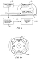
- Fig. 1 is a general block diagram of a system in accordance with the invention.
- Fig. 1a is a plan view depicting the invention as incorporated into a leakage flux inspection system.
- Fig. 2 is a showing of graphs plotting flux density and permeability separately against magnetic field strength.
- Fig. 3 is a particularly preferred embodiment of the eddy current unit of the Fig. 1 system provided jointly with a flux probe of a flux leakage system.
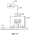
- Fig. 4 shows the Fig. 3 eddy current unit in association with apparatus which can constitute the magnetic field generator of the Fig. 1 system and also shows a specimen to be evaluated.
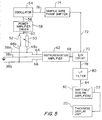
- Fig. 5 is a detailed block diagram of the drive and processing circuitry of the Fig. 1 system.
- the system thereof includes a magnetic field generator 10 which induces a magnetic field in a specimen S, typically, carbon steel plate, whose thickness is to be monitored.
- An eddy current unit 12 (inducer-sensor) is disposed in operative relation with the specimen at one surface thereof.
- Displacement driver 14 rotates magnetic field generator 10 and eddy current unit 12 in unison over the surface of the specimen.
- Eddy current unit 12 is connected by lines 16 to drive and processing circuitry 18, which functions to excite the eddy current unit coils and to derive therefrom output signals, which contain information concerning incremental magnetic permeability variations in the specimen and hence related thickness variation of the specimen in the course of displacement of the eddy current unit to different locations.
- Output signals of drive and processing circuitry 18 are conveyed to thickness display unit 20 over lines 22.
- Fig. 1a depicts the eddy current thickness sensor's incorporation into an existing leakage flux inspection system for tubular ferromagnetic products.
- the DC magnet coils DCM provide near magnetic saturation flux levels in the tubing/pipe T/P necessary for both systems to properly operate.
- the magnet and sensors assembly is rotated while product is longitudinally fed through the arrangement, circumferentially describing a barber-pole like helix of inspection and wall thickness monitoring.
- ECLF identifies a composite sensor including both eddy current and leakage flux components whereas LF indicates only leakage flux sensing components.
- the upper graph shows the variation of magnetic flux density (B) with magnetic field strength (H).
- saturation occurs at high field strength, where there is equal change in flux density with increase in field strength, i.e., the ratio thereof, which defines magnetic permeability, is unity.
- Applicants define an operating range for the subject invention to be as indicated in a nearly saturated area NSA, where in the upper graph flux density changes substantially linearly with increases or decreases in field strength.
- the lower graph of Fig. 2 shows incremental magnetic permeability (u) to increase sharply at the left hand portion corresponding with the rise of flux density to the knee of the upper graph and to decrease thereafter as flux density changes lesser with field increase.
- An essentially linear change in permeability is observed in applicants' selected range of operation, nearly saturated area NSA.
- a specimen nominal thickness NT is placed within NSA, such that thickness variations to some maximum thickness MT and to some least thickness LT can be measured.
- a sufficiently high test frequency is selected such that only the surface of the specimen with which eddy current unit 12 is juxtaposed, is sensed.
- the permeability of the surface is the most influential parameter affecting the impedance of coils of eddy current unit 12 primarily due to changes in coil inductance.
- the level of flux density in the specimen established by the DC magnetization field applied for a nominal thickness is such that some near-saturated value of permeability is achieved.
- the flux density in the remaining thickness decreases almost linearly away from saturation and results in a nearly linear relative increase in the specimen's permeability.
- the flux density in the remaining thickness increases almost linearly toward saturation and results in a nearly linear relative decrease in the specimen's permeability.
- drive and processing circuitry 18 drives the coils of eddy current unit 12 to induce eddy currents in the specimen, monitors the corresponding variations in the output signals of eddy current unit 12 and suitably scales the same to provide the desired showing in thickness display unit 20.
- the level of flux density required for the subject thickness measuring system is also identical to the levels of flux density required for known flux leakage systems. Accordingly, in a particularly preferred embodiment of the invention, the eddy current unit for thickness measurement is provided jointly with the flux probe of the flux leakage system, as shown in Fig.1a, specifically for tubular products.
- Composite sensor 24 of Fig. 3 thus includes centrally thereof a flux leakage probe having flux leakage coil 25, disposed about the center course 26a of flux coupling member 26, which has leg courses extending to the sensing face of composite sensor 24.
- the flux leakage output signals of coil 25 are provided to associated flux leakage processing circuitry over lines 28.
- a bobbin 30 is disposed about casing 32 of the flux leakage probe and has coils 34 and 36 of a thickness measurement eddy current unit wound thereon. Coils 34 and 36 are differentially connected and the junction of the coils and free ends are connected to lines 38a-38c, which correspond to lines 16 of Fig. 1 and both receive coil drive and provide the output of the thickness measurement eddy current unit.
- a thickness measurement eddy current unit in accordance with the invention may of course be configured independently of a flux leakage probe as desired.
- FIG. 4 composite sensor 24 of Fig. 3 is shown in juxtaposition with specimen S and interiorly of the legs of yoke magnet 40 having indicated poles N (north) and S (south).
- Yoke magnet 40 has coil 42 about its central course and the coil is driven by DC power supply 44 over lines 46, which corresponds to magnetic field generator 10 of Fig. 1.
- Fig. 5 depicts a particularized embodiment of drive and processing circuitry 18 of Fig. 1.
- Input line 38c is the line connected to the junction of the coils of the thickness measurement eddy current unit of Fig. 3 and is connected to ground.
- Input lines 38a and 38b are lines connected to the free ends of the coils of the thickness measurement eddy current unit and are connected, for sensor drive and balancing purposes over lines 48a and 48b to bridge resistors 50 and 52.
- the coils, with such connections, form with resistors 50 and 52 a bridge circuit and balancing resistor 50 is adjusted to provide a null condition on lines 38a and 38b.
- Oscillator 54 generates a high frequency signal, e.g., ten kilohertz, and applies the same over lines 56 to power amplifier driver 58, which is in turn connected over line 60 to the junction of resistors 50 and 52 for driving the coils of the thickness measurement eddy current unit.
- a high frequency signal e.g., ten kilohertz
- Input lines 38a and 38b are also connected over lines 64 and 66 to instrumentation amplifier 62 which provides output indication on lines 68 of differences between the signals on lines 38a and 38b.
- the difference indication is stored in sample and hold (S/H) circuit 70.
- Sample and hold circuit 70 is gated for sampling timing by a signal input thereto on line 72, which is derived from sample gate phase shifter 74.
- Phase shifter 74 is frequency locked to oscillator 54 by input thereto on line 76 and functions to provide a sampling signal on line 72 which is phase-shifted to accommodate phase change as between the driving of the coils of the thickness measurement eddy current unit and the output thereof.
- sample and hold circuit 70 is conveyed over line 78 to LP (low pass) filter 80 and the output thereof is provided to shifting/scaling amplifiers 82 over line 84.
- Amplifiers 82 furnish a signal on line 22 which is compatible with display unit 20 input requirements, unit 20 preferably being a digital meter.
- the method for determining variations in the thickness of a specimen to be evaluated along a given length thereof comprising the ensuing steps: applying a DC magnetic field to the specimen of level placing the specimen in a near magnetically saturated state at successive circular locations along the length; concurrently inducing eddy currents in a surface of the specimen successively at the plural locations; detecting resulting eddy currents so induced in the surface of the specimen at the plural locations; and deriving from variations as between successively detected eddy currents indication of variation in specimen thickness.
- applicants provide output indication selectively of variation of specimen thickness in excess of a predetermined permissible thickness variation.
- a system for this purpose is configured as for the absolute thickness measurement with the exception that a threshold comparator is connected between drive and processing circuitry 18 and display unit 20, such that display or alarm is conditioned on the comparator identifying a sensed result as exceeding a preset threshold corresponding to the predetermined permissible thickness variation.
Landscapes
- Physics & Mathematics (AREA)
- General Physics & Mathematics (AREA)
- Measurement Of Length, Angles, Or The Like Using Electric Or Magnetic Means (AREA)
Applications Claiming Priority (2)
| Application Number | Priority Date | Filing Date | Title |
|---|---|---|---|
| US14217193A | 1993-10-22 | 1993-10-22 | |
| US142171 | 1993-10-22 |
Publications (2)
| Publication Number | Publication Date |
|---|---|
| EP0650028A2 true EP0650028A2 (fr) | 1995-04-26 |
| EP0650028A3 EP0650028A3 (fr) | 1996-02-28 |
Family
ID=22498817
Family Applications (1)
| Application Number | Title | Priority Date | Filing Date |
|---|---|---|---|
| EP94103923A Withdrawn EP0650028A3 (fr) | 1993-10-22 | 1994-03-14 | Méthode et appareil pour mesurer l'épaisseur des spécimens. |
Country Status (1)
| Country | Link |
|---|---|
| EP (1) | EP0650028A3 (fr) |
Cited By (4)
| Publication number | Priority date | Publication date | Assignee | Title |
|---|---|---|---|---|
| WO2002033394A3 (fr) * | 2000-10-16 | 2002-10-10 | Em Tech Llc | Technique permettant de mesurer l'epaisseur d'un metal ferromagnetique a l'aide des signatures de permeabilite |
| WO2003044453A1 (fr) * | 2001-11-20 | 2003-05-30 | Em-Tech Llc | Utilisation d'un spectre de frequences electromagnetique et de la saturation magnetique pour mesurer l'epaisseur de metaux |
| DE102008059032A1 (de) * | 2008-09-09 | 2010-04-15 | Automation Dr. Nix Gmbh & Co. Kg | Verfahren und Vorrichtung zur Bestimmung ob eine Veränderung eines Substrats unter einer das Substrat bedeckenden Schicht vorliegt |
| CN113532255A (zh) * | 2021-07-27 | 2021-10-22 | 爱德森(厦门)电子有限公司 | 一种漏磁和涡流检测厚度的方法和装置 |
Family Cites Families (5)
| Publication number | Priority date | Publication date | Assignee | Title |
|---|---|---|---|---|
| US4292588A (en) * | 1978-12-18 | 1981-09-29 | Schlumberger Technology Corporation | Electromagnetic inspection tool for ferromagnetic casings |
| JPS58166203A (ja) * | 1982-03-26 | 1983-10-01 | Nuclear Fuel Ind Ltd | 核燃料用被覆管内面コ−テイング膜厚測定法ならびにその装置 |
| US4553095A (en) * | 1982-06-10 | 1985-11-12 | Westinghouse Electric Corp. | Eddy current thickness gauge with constant magnetic bias |
| US4710712A (en) * | 1984-04-11 | 1987-12-01 | Pa Incorporated | Method and apparatus for measuring defects in ferromagnetic elements |
| JPS61237052A (ja) * | 1985-04-15 | 1986-10-22 | Nippon Telegr & Teleph Corp <Ntt> | 亜鉛めつき鋼の腐食寿命診断器 |
-
1994
- 1994-03-14 EP EP94103923A patent/EP0650028A3/fr not_active Withdrawn
Cited By (6)
| Publication number | Priority date | Publication date | Assignee | Title |
|---|---|---|---|---|
| WO2002033394A3 (fr) * | 2000-10-16 | 2002-10-10 | Em Tech Llc | Technique permettant de mesurer l'epaisseur d'un metal ferromagnetique a l'aide des signatures de permeabilite |
| WO2003044453A1 (fr) * | 2001-11-20 | 2003-05-30 | Em-Tech Llc | Utilisation d'un spectre de frequences electromagnetique et de la saturation magnetique pour mesurer l'epaisseur de metaux |
| DE102008059032A1 (de) * | 2008-09-09 | 2010-04-15 | Automation Dr. Nix Gmbh & Co. Kg | Verfahren und Vorrichtung zur Bestimmung ob eine Veränderung eines Substrats unter einer das Substrat bedeckenden Schicht vorliegt |
| DE102008059032B4 (de) * | 2008-09-09 | 2013-11-07 | Automation Dr. Nix Gmbh & Co. Kg | Verfahren und Vorrichtung zur Bestimmung ob eine Veränderung eines Substrats unter einer das Substrat bedeckenden Schicht vorliegt |
| CN113532255A (zh) * | 2021-07-27 | 2021-10-22 | 爱德森(厦门)电子有限公司 | 一种漏磁和涡流检测厚度的方法和装置 |
| CN113532255B (zh) * | 2021-07-27 | 2024-01-12 | 爱德森(厦门)电子有限公司 | 一种漏磁和涡流检测厚度的方法和装置 |
Also Published As
| Publication number | Publication date |
|---|---|
| EP0650028A3 (fr) | 1996-02-28 |
Similar Documents
| Publication | Publication Date | Title |
|---|---|---|
| US6239593B1 (en) | Method and system for detecting and characterizing mechanical damage in pipelines using nonlinear harmonics techniques | |
| US5828211A (en) | Determining stress in ferromagnetic materials from measurements of magnetic anisotropy and magnetic permeability | |
| AU2002216205B2 (en) | Measurement of stress in a ferromagnetic material | |
| US4352065A (en) | Nondestructive electromagnetic inspection of pipelines incorporated in an electrically closed loop | |
| Sadek | NDE technologies for the examination of heat exchangers and boiler tubes-principles, advantages and limitations | |
| GB2245072A (en) | Eddy current probe for detecting internal defects in ferromagnetic tubes | |
| JP2001141701A (ja) | 保磁力の測定方法 | |
| JP2766929B2 (ja) | 非破壊検査装置 | |
| WO2011025049A1 (fr) | Procédé d'inspection de soudure en acier inoxydable austénitique | |
| WO2008072508A1 (fr) | Instrument d'essai non destructif et procédé d'essai non destructif | |
| US5047717A (en) | Method and apparatus for measuring internal mechanical stress of a ferromagnetic body by determining the third harmonic of the induction | |
| JP3910222B2 (ja) | 疲労度測定装置 | |
| EP0650028A2 (fr) | Méthode et appareil pour mesurer l'épaisseur des spécimens | |
| JP2005127963A (ja) | 非破壊検査方法及びその装置 | |
| Pu | A new system for defects inspection of boiler water wall tubes using a combination of EMAT and MFL | |
| US12332211B2 (en) | Method for determining a materials characteristic value of magnetizable metal bodies by means of a micromagnetic sensor assembly, and corresponding sensor assembly | |
| WO2023143737A1 (fr) | Détermination de la contrainte mécanique dans des tuyaux à l'aide d'une analyse de contrainte magnétique | |
| JP7450305B1 (ja) | 検査装置及び検査方法 | |
| GB2257528A (en) | Locating the position of ferrous reinforcement in a structure | |
| RU2139520C1 (ru) | Способ измерения скорости внутреннего разрушения полых конструкций из ферромагнитного материала и устройство для его реализации | |
| JPH01269049A (ja) | 金属材料の劣化検査方法 | |
| Vértesy et al. | Nondestructive material evaluation by novel electromagnetic methods | |
| JP2855186B2 (ja) | 複数周波数磁化による表面傷の非破壊計測方法 | |
| Lo | Characterization of residual stresses in ferrous components by magnetic anisotropy measurements using a hall effect sensor array probe | |
| EP0717281A1 (fr) | Méthode et appareil pour la détection des défauts |
Legal Events
| Date | Code | Title | Description |
|---|---|---|---|
| PUAI | Public reference made under article 153(3) epc to a published international application that has entered the european phase |
Free format text: ORIGINAL CODE: 0009012 |
|
| AK | Designated contracting states |
Kind code of ref document: A2 Designated state(s): DE GB |
|
| PUAL | Search report despatched |
Free format text: ORIGINAL CODE: 0009013 |
|
| AK | Designated contracting states |
Kind code of ref document: A3 Designated state(s): DE GB |
|
| STAA | Information on the status of an ep patent application or granted ep patent |
Free format text: STATUS: THE APPLICATION HAS BEEN WITHDRAWN |
|
| 18W | Application withdrawn |
Withdrawal date: 19960307 |