EP0650075A2 - Localisation automatique à ultrasons de cibles implantées dans le corps humain - Google Patents
Localisation automatique à ultrasons de cibles implantées dans le corps humain Download PDFInfo
- Publication number
- EP0650075A2 EP0650075A2 EP94116661A EP94116661A EP0650075A2 EP 0650075 A2 EP0650075 A2 EP 0650075A2 EP 94116661 A EP94116661 A EP 94116661A EP 94116661 A EP94116661 A EP 94116661A EP 0650075 A2 EP0650075 A2 EP 0650075A2
- Authority
- EP
- European Patent Office
- Prior art keywords
- fiducial marker
- transducer
- implanted
- acoustic impedance
- marker
- Prior art date
- Legal status (The legal status is an assumption and is not a legal conclusion. Google has not performed a legal analysis and makes no representation as to the accuracy of the status listed.)
- Withdrawn
Links
- 230000004807 localization Effects 0.000 title description 12
- 210000003484 anatomy Anatomy 0.000 title description 5
- 238000002604 ultrasonography Methods 0.000 claims abstract description 56
- 239000000463 material Substances 0.000 claims abstract description 39
- 238000002592 echocardiography Methods 0.000 claims abstract description 29
- 239000003550 marker Substances 0.000 claims description 121
- 238000000034 method Methods 0.000 claims description 59
- 230000004044 response Effects 0.000 claims description 22
- 210000003625 skull Anatomy 0.000 claims description 15
- 210000004761 scalp Anatomy 0.000 claims description 11
- 210000000988 bone and bone Anatomy 0.000 claims description 10
- 230000002452 interceptive effect Effects 0.000 claims description 7
- 238000003384 imaging method Methods 0.000 claims description 5
- 238000011404 fractionated radiotherapy Methods 0.000 claims description 4
- 239000011521 glass Substances 0.000 claims description 4
- 238000002675 image-guided surgery Methods 0.000 claims description 3
- 238000001514 detection method Methods 0.000 claims description 2
- 239000000523 sample Substances 0.000 description 8
- 230000033001 locomotion Effects 0.000 description 6
- 230000003287 optical effect Effects 0.000 description 6
- 238000004458 analytical method Methods 0.000 description 5
- 210000004003 subcutaneous fat Anatomy 0.000 description 5
- XLYOFNOQVPJJNP-UHFFFAOYSA-N water Substances O XLYOFNOQVPJJNP-UHFFFAOYSA-N 0.000 description 5
- 238000013459 approach Methods 0.000 description 3
- 239000012636 effector Substances 0.000 description 3
- 238000013507 mapping Methods 0.000 description 3
- 230000005855 radiation Effects 0.000 description 3
- 238000002591 computed tomography Methods 0.000 description 2
- 230000008878 coupling Effects 0.000 description 2
- 238000010168 coupling process Methods 0.000 description 2
- 238000005859 coupling reaction Methods 0.000 description 2
- 239000013078 crystal Substances 0.000 description 2
- 238000013461 design Methods 0.000 description 2
- 239000000284 extract Substances 0.000 description 2
- 238000000605 extraction Methods 0.000 description 2
- 238000002513 implantation Methods 0.000 description 2
- 230000003902 lesion Effects 0.000 description 2
- 239000000203 mixture Substances 0.000 description 2
- 229920003229 poly(methyl methacrylate) Polymers 0.000 description 2
- 229920000642 polymer Polymers 0.000 description 2
- 239000004926 polymethyl methacrylate Substances 0.000 description 2
- 230000008569 process Effects 0.000 description 2
- 238000001356 surgical procedure Methods 0.000 description 2
- 210000001519 tissue Anatomy 0.000 description 2
- 230000009466 transformation Effects 0.000 description 2
- 238000012285 ultrasound imaging Methods 0.000 description 2
- 206010028980 Neoplasm Diseases 0.000 description 1
- 240000007320 Pinus strobus Species 0.000 description 1
- 239000007864 aqueous solution Substances 0.000 description 1
- 239000000560 biocompatible material Substances 0.000 description 1
- 238000001574 biopsy Methods 0.000 description 1
- 210000004204 blood vessel Anatomy 0.000 description 1
- 238000004364 calculation method Methods 0.000 description 1
- 238000001444 catalytic combustion detection Methods 0.000 description 1
- 239000000919 ceramic Substances 0.000 description 1
- 230000008859 change Effects 0.000 description 1
- 230000001934 delay Effects 0.000 description 1
- 230000000694 effects Effects 0.000 description 1
- 238000013213 extrapolation Methods 0.000 description 1
- 239000012530 fluid Substances 0.000 description 1
- 210000003128 head Anatomy 0.000 description 1
- 229920001903 high density polyethylene Polymers 0.000 description 1
- 239000004700 high-density polyethylene Substances 0.000 description 1
- 239000012216 imaging agent Substances 0.000 description 1
- 238000003780 insertion Methods 0.000 description 1
- 230000037431 insertion Effects 0.000 description 1
- 238000007689 inspection Methods 0.000 description 1
- 230000007774 longterm Effects 0.000 description 1
- 238000002595 magnetic resonance imaging Methods 0.000 description 1
- 239000002480 mineral oil Substances 0.000 description 1
- 235000010446 mineral oil Nutrition 0.000 description 1
- 230000000926 neurological effect Effects 0.000 description 1
- 229920000620 organic polymer Polymers 0.000 description 1
- TWNQGVIAIRXVLR-UHFFFAOYSA-N oxo(oxoalumanyloxy)alumane Chemical compound O=[Al]O[Al]=O TWNQGVIAIRXVLR-UHFFFAOYSA-N 0.000 description 1
- RVTZCBVAJQQJTK-UHFFFAOYSA-N oxygen(2-);zirconium(4+) Chemical compound [O-2].[O-2].[Zr+4] RVTZCBVAJQQJTK-UHFFFAOYSA-N 0.000 description 1
- 239000002861 polymer material Substances 0.000 description 1
- 238000002600 positron emission tomography Methods 0.000 description 1
- 230000003439 radiotherapeutic effect Effects 0.000 description 1
- 238000005070 sampling Methods 0.000 description 1
- 239000000243 solution Substances 0.000 description 1
- 238000002560 therapeutic procedure Methods 0.000 description 1
- 230000000007 visual effect Effects 0.000 description 1
- 229910001928 zirconium oxide Inorganic materials 0.000 description 1
Images



Classifications
-
- A—HUMAN NECESSITIES
- A61—MEDICAL OR VETERINARY SCIENCE; HYGIENE
- A61B—DIAGNOSIS; SURGERY; IDENTIFICATION
- A61B8/00—Diagnosis using ultrasonic, sonic or infrasonic waves
- A61B8/08—Clinical applications
- A61B8/0833—Clinical applications involving detecting or locating foreign bodies or organic structures
-
- A—HUMAN NECESSITIES
- A61—MEDICAL OR VETERINARY SCIENCE; HYGIENE
- A61B—DIAGNOSIS; SURGERY; IDENTIFICATION
- A61B34/00—Computer-aided surgery; Manipulators or robots specially adapted for use in surgery
- A61B34/20—Surgical navigation systems; Devices for tracking or guiding surgical instruments, e.g. for frameless stereotaxis
-
- A—HUMAN NECESSITIES
- A61—MEDICAL OR VETERINARY SCIENCE; HYGIENE
- A61B—DIAGNOSIS; SURGERY; IDENTIFICATION
- A61B8/00—Diagnosis using ultrasonic, sonic or infrasonic waves
- A61B8/42—Details of probe positioning or probe attachment to the patient
- A61B8/4209—Details of probe positioning or probe attachment to the patient by using holders, e.g. positioning frames
- A61B8/4218—Details of probe positioning or probe attachment to the patient by using holders, e.g. positioning frames characterised by articulated arms
-
- A—HUMAN NECESSITIES
- A61—MEDICAL OR VETERINARY SCIENCE; HYGIENE
- A61B—DIAGNOSIS; SURGERY; IDENTIFICATION
- A61B8/00—Diagnosis using ultrasonic, sonic or infrasonic waves
- A61B8/42—Details of probe positioning or probe attachment to the patient
- A61B8/4245—Details of probe positioning or probe attachment to the patient involving determining the position of the probe, e.g. with respect to an external reference frame or to the patient
-
- A—HUMAN NECESSITIES
- A61—MEDICAL OR VETERINARY SCIENCE; HYGIENE
- A61B—DIAGNOSIS; SURGERY; IDENTIFICATION
- A61B90/00—Instruments, implements or accessories specially adapted for surgery or diagnosis and not covered by any of the groups A61B1/00 - A61B50/00, e.g. for luxation treatment or for protecting wound edges
- A61B90/39—Markers, e.g. radio-opaque or breast lesions markers
-
- A—HUMAN NECESSITIES
- A61—MEDICAL OR VETERINARY SCIENCE; HYGIENE
- A61B—DIAGNOSIS; SURGERY; IDENTIFICATION
- A61B17/00—Surgical instruments, devices or methods
- A61B2017/00017—Electrical control of surgical instruments
- A61B2017/00199—Electrical control of surgical instruments with a console, e.g. a control panel with a display
-
- A—HUMAN NECESSITIES
- A61—MEDICAL OR VETERINARY SCIENCE; HYGIENE
- A61B—DIAGNOSIS; SURGERY; IDENTIFICATION
- A61B34/00—Computer-aided surgery; Manipulators or robots specially adapted for use in surgery
- A61B34/20—Surgical navigation systems; Devices for tracking or guiding surgical instruments, e.g. for frameless stereotaxis
- A61B2034/2046—Tracking techniques
- A61B2034/2055—Optical tracking systems
-
- A—HUMAN NECESSITIES
- A61—MEDICAL OR VETERINARY SCIENCE; HYGIENE
- A61B—DIAGNOSIS; SURGERY; IDENTIFICATION
- A61B34/00—Computer-aided surgery; Manipulators or robots specially adapted for use in surgery
- A61B34/20—Surgical navigation systems; Devices for tracking or guiding surgical instruments, e.g. for frameless stereotaxis
- A61B2034/2046—Tracking techniques
- A61B2034/2063—Acoustic tracking systems, e.g. using ultrasound
-
- A—HUMAN NECESSITIES
- A61—MEDICAL OR VETERINARY SCIENCE; HYGIENE
- A61B—DIAGNOSIS; SURGERY; IDENTIFICATION
- A61B34/00—Computer-aided surgery; Manipulators or robots specially adapted for use in surgery
- A61B34/20—Surgical navigation systems; Devices for tracking or guiding surgical instruments, e.g. for frameless stereotaxis
- A61B2034/2072—Reference field transducer attached to an instrument or patient
-
- A—HUMAN NECESSITIES
- A61—MEDICAL OR VETERINARY SCIENCE; HYGIENE
- A61B—DIAGNOSIS; SURGERY; IDENTIFICATION
- A61B90/00—Instruments, implements or accessories specially adapted for surgery or diagnosis and not covered by any of the groups A61B1/00 - A61B50/00, e.g. for luxation treatment or for protecting wound edges
- A61B90/06—Measuring instruments not otherwise provided for
- A61B2090/067—Measuring instruments not otherwise provided for for measuring angles
-
- A—HUMAN NECESSITIES
- A61—MEDICAL OR VETERINARY SCIENCE; HYGIENE
- A61B—DIAGNOSIS; SURGERY; IDENTIFICATION
- A61B90/00—Instruments, implements or accessories specially adapted for surgery or diagnosis and not covered by any of the groups A61B1/00 - A61B50/00, e.g. for luxation treatment or for protecting wound edges
- A61B90/36—Image-producing devices or illumination devices not otherwise provided for
- A61B90/37—Surgical systems with images on a monitor during operation
- A61B2090/378—Surgical systems with images on a monitor during operation using ultrasound
-
- A—HUMAN NECESSITIES
- A61—MEDICAL OR VETERINARY SCIENCE; HYGIENE
- A61B—DIAGNOSIS; SURGERY; IDENTIFICATION
- A61B90/00—Instruments, implements or accessories specially adapted for surgery or diagnosis and not covered by any of the groups A61B1/00 - A61B50/00, e.g. for luxation treatment or for protecting wound edges
- A61B90/39—Markers, e.g. radio-opaque or breast lesions markers
- A61B2090/3925—Markers, e.g. radio-opaque or breast lesions markers ultrasonic
-
- A—HUMAN NECESSITIES
- A61—MEDICAL OR VETERINARY SCIENCE; HYGIENE
- A61B—DIAGNOSIS; SURGERY; IDENTIFICATION
- A61B90/00—Instruments, implements or accessories specially adapted for surgery or diagnosis and not covered by any of the groups A61B1/00 - A61B50/00, e.g. for luxation treatment or for protecting wound edges
- A61B90/39—Markers, e.g. radio-opaque or breast lesions markers
- A61B2090/3937—Visible markers
- A61B2090/3945—Active visible markers, e.g. light emitting diodes
-
- A—HUMAN NECESSITIES
- A61—MEDICAL OR VETERINARY SCIENCE; HYGIENE
- A61B—DIAGNOSIS; SURGERY; IDENTIFICATION
- A61B90/00—Instruments, implements or accessories specially adapted for surgery or diagnosis and not covered by any of the groups A61B1/00 - A61B50/00, e.g. for luxation treatment or for protecting wound edges
- A61B90/50—Supports for surgical instruments, e.g. articulated arms
-
- A—HUMAN NECESSITIES
- A61—MEDICAL OR VETERINARY SCIENCE; HYGIENE
- A61N—ELECTROTHERAPY; MAGNETOTHERAPY; RADIATION THERAPY; ULTRASOUND THERAPY
- A61N5/00—Radiation therapy
- A61N5/10—X-ray therapy; Gamma-ray therapy; Particle-irradiation therapy
- A61N5/1048—Monitoring, verifying, controlling systems and methods
- A61N5/1049—Monitoring, verifying, controlling systems and methods for verifying the position of the patient with respect to the radiation beam
-
- Y—GENERAL TAGGING OF NEW TECHNOLOGICAL DEVELOPMENTS; GENERAL TAGGING OF CROSS-SECTIONAL TECHNOLOGIES SPANNING OVER SEVERAL SECTIONS OF THE IPC; TECHNICAL SUBJECTS COVERED BY FORMER USPC CROSS-REFERENCE ART COLLECTIONS [XRACs] AND DIGESTS
- Y10—TECHNICAL SUBJECTS COVERED BY FORMER USPC
- Y10S—TECHNICAL SUBJECTS COVERED BY FORMER USPC CROSS-REFERENCE ART COLLECTIONS [XRACs] AND DIGESTS
- Y10S128/00—Surgery
- Y10S128/916—Ultrasound 3-D imaging
Definitions
- the present invention relates to locating a position of a object implanted in a portion of the anatomy, the object having at least a portion which is in a vicinity of a material having a different acoustic impedance than an acoustic impedance of that portion of the object. More particularly, the present invention relates to the localization of implanted targets using amplitude-mode (A-mode) ultrasound techniques and a coordinate space digitizer.
- A-mode amplitude-mode
- the automatic implanted target localization approach may be used to locate small fluid-filled polymer cylinders implanted in human skull, which are preferably flush with the surface of the skull, beneath the scalp and subcutaneous fat. These permanently-implanted cylinders are intended to serve as fiducial markers for the registration of tomographic image volumes with physical space in neurosurgical cases, as well as for tracking a patient over time.
- Tomographic imaging modalities such as computer tomography (CT), magnetic resonance imaging (MRI), and positron emission tomography (PET), produce a three-dimensional image volume as a set of three-dimensional "slices".
- CT computer tomography
- MRI magnetic resonance imaging
- PET positron emission tomography
- image volumes contain the information necessary for surgical or radiotherapeutic planning.
- information may include the three-dimensional distances between sites of interest such as tumors, the location of blood vessels which must be avoided, and lesion margin delineation often superior to that discernible by visual tissue inspection.
- Space registration establishes a one-to-one mapping between points in the image sets or between points in one or more image sets and physical space.
- the transformation between coordinate systems is calculated based on the location of a set of at least three common landmarks, or fiducial markers, in each representation.
- the actual fiducial point is the geometric center of the fiducial marker.
- the accuracy of the mapping between coordinate systems depends on the accuracy with which the coordinates of the fiducial markers' centers are known in each three-dimensional space.
- the fiducial markers provide a frame of reference to make image-to-image or image-to-physical space registration possible.
- a general technique for using fiducial markers to obtain registration of image data across time is set forth in U.S. Patent No. 4,991,579 to Allen et al., which is incorporated herein by reference.
- Fiducial markers for accurate image-to-physical space registration must be rigidly located and must be composed of materials making them visible in the imaging modalities of interest.
- U.S. Patent Application Serial No. 08/017,167 to McCrory et al. which is incorporated herein by reference, describes the design and composition of fiducial markers for neurosurgical image registration and image-physical space registration, as well as a method for localizing the center of the imaged markers in the image volumes.
- This patent application describes two types of markers including temporary markers anchored in the skull for rigidity but with the image-visible portion protruding above the scalp, and permanent markers implanted into the skull beneath the scalp and subcutaneous fat.
- Permanent markers allow the comparison of images over time for follow-up therapy. Permanent markers also allow the delivery of fractionated radiotherapy, in which small doses of radiation are administered in multiple sessions to maximize the dose delivered to the target lesion while minimizing the damage to surrounding tissue. Fractionated radiotherapy requires the same fiducial framework to be present, in an unchanged position, for each treatment so that the radiation beam may be properly directed relative to the fiducial markers as determined from the pretreatment images. Temporary markers and stereotactic frames can neither remain in position long enough nor be re-affixed accurately to satisfy this requirement.
- image-to-physical space registration requires a method for establishing the coordinate system in physical space.
- coordinate space digitizers including specific pointing devices have been developed which define a coordinate space and pass the three-dimensional coordinates of the endpoint to an attached computer.
- an articulated arm has joints that track the angular position of each link, allowing the attached computer to calculate the endpoint coordinates.
- a less cumbersome alternative is a wand with infrared light emitting diodes (LEDs) along its shaft in which the LEDs are strobed in sequence and an infrared camera attached to a computer notes the location of the LEDs relative to a set of reference LEDs in a fixed position.
- LEDs infrared light emitting diodes
- a means for locating the center of the fiducial markers in the coordinate system defined by the pointing device is also required of a system which correlates neurological image space and physical space.
- the fiducial position can be recorded simply by touching the fiducial marker with the pointing device.
- locating the precise three-dimensional position of the marker is much more challenging.
- a target localization method to address this task has previously become necessary in the field of registration of image volumes with physical space in neurosurgical cases.
- the system display can provide interactive surgical guidance.
- the location of the endpoint of the pointing device is indicated on a display of the appropriate slice through the image volumes.
- U.S. Patent No. 5,197,476 to Nowacki et al. which is also incorporated herein by reference, discloses an ultrasound probe coupled with an infrared LED-based pointing device to locate a target in a living body.
- a three-dimensional frame containing a plurality of infrared lights is placed on a table.
- a computer strobes the infrared lights and the position of the infrared lights is monitored by a pair of infrared sensitive cameras and stored in the computer.
- a hand held ultrasonic probe is provided with a plurality of infrared lights so that the probe can be monitored by the cameras.
- the computer compares the positions of the probe lights with the initial position of the frame infrared lights to accurately determine the position of the probe so that the position of the target in the body may be displayed on a computer monitor.
- the approach disclosed in the Nowacki et al. patent employs a brightness-mode (B-mode) ultrasound imaging and requires a trained expert to visually recognize when the desired target is displayed.
- B-mode brightness-mode
- the present invention relates to a method and apparatus for automatically localizing the three-dimensional coordinates of a symmetrically-shaped implanted target.
- the ultrasonic method is based on differences in the characteristic acoustic impedance (Z0) of the target and that of the surrounding material or surrounding materials as well as on the time delays between ultrasonic echoes.
- the present invention uses A-mode ultrasound which produces one-dimensional, time domain "signals". Echoes received by the transducer are indicated as deflections in the signal and the amplitude of these deflections is proportional to the difference in acoustic impedances of the materials which form the interface from which the echo arose.
- B-mode ultrasound imaging produces a two-dimensional image such as that provided on a video display, where each displayed line of the image corresponds to a single A-mode signal acquired from adjacent positions. The brightness or intensity of each pixel or dot along that line corresponds to the amplitude of received echoes.
- an A-mode ultrasonic transducer is attached to a pointing device which digitizes the coordinates of physical space.
- the automatic target detection algorithm is implemented on a computer that receives the reflected ultrasound signals along with the transducer position and orientation information.
- a position of the target or fiducial marker in a coordinate system of the pointing device is determined in response to the received echoes and the position and orientation of the transducer.
- the present invention is based on the following ultrasonic principles.
- an ultrasonic pulse When an ultrasonic pulse is emitted from a transducer, it propagates through a material until it reaches an interface with a material of different characteristic acoustic impedance. At this interface, a portion of the power of the pulse is reflected back to be received by the transducer and the remainder propagates on to deeper interfaces.
- the ratio of reflected to transmitted power is proportional to the square of the difference in the characteristic acoustic impedances of the two materials.
- the time delay between the echoes received by the transducer may be multiplied by the speed of sound in the intervening material to obtain the distance traveled by the ultrasonic pulse and the speed of sound in the intervening material.
- the present invention provides accurate localization, appropriate for localizing the center of small targets such as those a few millimeters in diameter. Accuracy is critical for the described application of the invention to image-to-physical space registration.
- An example of a fiducial marker design for that application is a cylinder, 3 mm in diameter, 4 mm in height, consisting of a polymer shell and an aqueous solution. Such a marker would be implanted into the skull flush with the surface of the skull, beneath the skin ad subcutaneous fat.
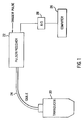
- FIG. 1 illustrates an A-mode ultrasound transducer arranged with associated hardware according to a embodiment of the present invention.
- FIG. 2 is a mechanical articulated arm which may be used as a pointing device in an image-guided neurosurgery system.
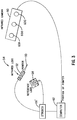
- FIG. 3 is a schematic of the components of an optical pointing device system.
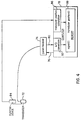
- FIG. 4 illustrates the acquisition of signal and position information from an ultrasound transducer coupled to a pointing device according to an embodiment of the present invention.
- FIG. 5 illustrates a position of a transducer piston near a target and the use of an ultrasound standoff pad in placing the target in the optimal range of the ultrasound beam.
- FIG. 6, which includes FIG. 6(a), FIG. 6(b), and FIG. 6(c), illustrates different relative positions of a transducer and a target during an ultrasound location method according to an embodiment of the present invention.
- FIG. 7(a), FIG. 7(b) and FIG. 7(c), which together comprise FIG. 7, illustrate a correspondence between the positions illustrated in FIG. 6(a), FIG. 6(b) and FIG. 6(c) and corresponding received reflections including a target interface echo signal on which the automatic localization technique according to the present invention is based.
- FIG. 8 which includes FIG. 8(a) and FIG. 8(b), illustrates a low-impedance implanted fiducial marker for a neurosurgical space registration application of the present invention.
- FIG. 9, which includes FIG. 9(a) and FIG. 9(b), illustrates expected received signals for the relative positions of the transducer piston and the fiducial marker illustrated in FIG. 8(a) and 8(b), respectively.
- FIG. 10 illustrates an embodiment of the present invention in which a low impedance fiducial marker with a high impedance layer is used.
- FIG. 11 illustrates expected received signals for the relative positions of the transducer piston and the fiducial marker illustrated in FIG. 10.
- FIG. 12 illustrates an embodiment of the present invention relating to surgical applications thereof.
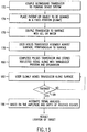
- FIG. 13 illustrates a flow chart of an automatic ultrasonic localization method of implanted targets according to an embodiment of the present invention.
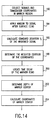
- FIG. 14 illustrates one embodiment of an automatic signal analysis determination which may be used in implementing an embodiment of the present invention.
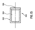
- FIG. 15 illustrates a fiducial marker which may be used in implementing an embodiment of the present invention.
- an A-mode ultrasound transducer possessing a rotationally-symmetric beam (for example, a circular, single-crystal piston transducer) is attached to a pointing device such that the connected computer may track the coordinates and orientation of the transducer as the transducer is moved through space.
- a rotationally-symmetric beam for example, a circular, single-crystal piston transducer
- FIG. 1 illustrates an example of an A-mode ultrasound transducer 20 with a beam (not illustrated) having a circular cross-section.
- a pulser/receiver 22 provides an electrical trigger signal to the transducer 20 via a cable 24.
- the electrical trigger signal transducer 20 emits a ultrasonic pulse.
- the transducer 20 receives reflected acoustic waves and converts them to electrical time-domain signals, passing them to the pulser/receiver 22 via cable 24.
- These signals may be transferred to a computer 26 via an analog-to-digital (A/D) converter 28.
- the trigger pulse signal input to pulser/receiver 22 may be provided by computer 26.
- an operator translates the transducer 20 along a surface of interest perpendicular to the surface and with the aid of a coupling medium, such as water, acoustic scanning gel, or mineral oil.
- the computer 26 pulses the transducer 20 via pulser/receiver 22 and receives the reflected echoes along with the corresponding transducer location ad orientation as determined by the pointing device system.
- a coupling medium such as water, acoustic scanning gel, or mineral oil.
- the computer 26 pulses the transducer 20 via pulser/receiver 22 and receives the reflected echoes along with the corresponding transducer location ad orientation as determined by the pointing device system.
- Z0 characteristic acoustic impedances
- a larger-amplitude echo results. Therefore, if an implanted target is composed of a material with an acoustic impedance Z0 that is much greater or much less than the layers above or below it, a "target interface echo" will result. If enough prior knowledge exists to ensure that no other similar reflectors can be located in the expected depth range of the imbedded target, then the target can be automatically detected according to the present invention based on the presence of such a target interface echo.
- the amplitude of the target interface echo will be a maximum when the largest portion of the ultrasound beam reaches and is reflected from that interface. If the ultrasound beam has a diameter greater than or approximately the same as the diameter of the target, the maximum echo amplitude occurs when the transducer is centered over the target.
- This theory coupled with the position of the transducer corresponding to each received signal, may be used to map out the position of the target in the lateral plane, the plane perpendicular to the ultrasound beam. To then determine the depth of the target from the transducer face, the present invention detects the time delay between received echoes. Based on the knowledge of the speed of sound in the intervening materials, the direction of the transducer's orientation may be extrapolated along to estimate the three-dimensional location of the target.
- FIG. 2 illustrates an example of such a pointing device system to which a ultrasound transducer may be attached according to an embodiment of the present invention.
- FIG. 2 illustrates an articulated arm 34 such as that used in the interactive, image-guided neurosurgery system described in U.S. Patent No. 5,142,930 to Allen et al.
- an external arm 34 is fixed to a base 36, which is movably fixed to some location.
- the arm 34 carries a tool 38 including an end tip 40 which is changeable and, for purposes of the present invention, is a pointing device which may include an attached ultrasound unit.
- a sensor (not illustrated in FIG. 2) which comprises an ultrasonic detector may be attached in place of the tool 38 and the end tip 40 of the tool 38 in order to practice the present invention.
- the arm 34 has two arm lengths 40A, 40B.
- the first arm length 40A is coupled to the base by two gimbal joints 42.
- the first arm length 40A therefore has two degrees of motion, as provided by the two gimbal joints 42.
- a second arm length 40B is coupled to the first arm length 40A by a second pair of gimbal joints 42.
- the second pair of gimbal joints 42 provides the second arm length 40B with two additional degrees of motion.
- the second arm length 40B therefore has four degrees of motion relative to the base 36 of the arm 34.
- a tool holder 44 is coupled to the second arm length 40B through a pair of gimbal joints 42.
- the tool holder 44 can hold any of a number of different tools, including a pointer, an ultrasound unit, a surgical laser, a biopsy probe, a radiation beam collimator, etc.
- the tool held by the tool holder 44 is an ultrasound unit (not illustrated in FIG. 2).
- a third pair of gimbal joints 42 provides the tool 38 with two additional degrees of motion, so that the tool 38 has 6 degrees of motion relative to the base 36.
- optical encoders 46 The exact positioning of the tool 38 relative to the base 36 may be monitored by optical encoders 46.
- One optical encoder 46 is assigned to each gimbal joint 42.
- Each gimbal joint 42 is individually rotated around its pivot ad the optical encoder 46 determines the precise amount of rotation of the gimbal joint 42 around its pivot.
- the information from each of the six optical encoders 46 is provided to a programmable computer (not illustrated in FIG. 2) via wires 48.
- the programmable computer can therefore precisely track the movement of the tool 38 relative to the base 36 by keeping track of the individual rotations of the gimbal joints 42 around their pivots.
- LEDs infrared light emitting diodes
- the LEDs are strobed in sequence and an infrared camera attached to a computer notes the location of the LEDs relative to a set of reference LEDs in a feed position.
- Optotrak/3020 Northern Digital, Inc., Waterloo, Ontario
- FIG. 3 One implementation of this system is described in U.S. Patent No. 5,197,476 issued to Nowacki et al.
- the optical system illustrated in FIG. 3 tracks the coordinates and orientation of an object 50 which is illustrated as a pointer, but may be replaced by an A-mode ultrasound transducer to implement an embodiment of the present invention.
- a shaft 52 extends from object 50 with a plurality of infrared light emitting diodes (LEDs) on its surface.
- a cable connects the probe 54 (consisting of shaft 52 and end-effector 50) to a strober 56.
- the probe 54 may be easily and freely manipulated by a user.
- Mounted in a fixed position near the region of interest is a set of reference infrared LEDs 58 referred to as a rigid body. This set of reference LEDs 58 establishes the origin of a three-dimensional coordinate system in physical space.
- Position sensor 60 includes three linear charge coupled device (CCD) cameras 60A, 60B, 60C with cylindrical optics placed in front of the CCDs to compress the field of view into a single line.
- CCD charge coupled device
- the output of each CCD 60A, 60B, 60C is captured by a separate processor (not illustrated) which extracts the object's position in that view.
- a fourth processor receives the output of each of the three separate individual processors and triangulates the location of an infrared LED and passes it to a computer 62.
- the computer 62 is able to calculate the time-distinct location of the end-effector 50 with respect to the rigid body of reference infrared LEDs 58.
- a ultrasound transducer may be attached to any pointing device such that the coordinates and orientation of the transducer are continuously passed to the connected computer, as illustrated, for example, in FIG. 4.
- an ultrasound signal 80 of specific time duration is acquired from pulser/receiver 74, digitized by a A/D converter 82 which may be included in computer 78, and stored as a signal (i) in a memory 88 of the computer 78.
- the rate at which the A/D converter 82 samples the analog ultrasound signal 80 must be sufficient to adequately represent the signal.
- the sampling frequency should be at least twice the frequency bandwidth of the ultrasound signal.
- a transducer position calculator 86 calculates a transducer position (i) in response to the data provided from pointing device 84 which is stored in memory 88 along with the signal (i). In this manner, signal/position pairs are acquired while a region of a object or anatomy are scanned with the transducer assembly.
- FIG. 5 illustrates a position of a transducer piston 92 near a target 94.
- An ultrasound stand-off pad 96 is used in placing the target 94 in a optimal range of an ultrasound beam 98 (illustrated by a dotted line) of the transducer piston 92.
- a coupling medium such as acoustic gel or water.
- the ultrasonic stand-off pad 96 may be used to place the expected target depth in an optimal range of the ultrasound beam 98 depending on the expected depth of the implanted target 94 and the type of transducer used.
- Stand-off 96 may be a layer or "pad" of a gelatinous material or a water path.
- FIG. 6 which includes FIG. 6(a), FIG. 6(b) and FIG. 6(c), illustrates this concept as applied to a low-Z0 target 110 (e.g., a cylindrical fiducial marker) implanted in a high-Z0 material 112 (e.g., the human skull) covered by two layers 114, 116 of low-Z0 material (e.g., scalp and fat).
- a low-Z0 target 110 e.g., a cylindrical fiducial marker
- a high-Z0 material 112 e.g., the human skull
- two layers 114, 116 of low-Z0 material e.g., scalp and fat
- FIG. 6(c) illustrate the relative position of the transducer piston 118 and the target 110.
- Fig. 7(a), FIG. 7(b) and FIG. 7(c) illustrate corresponding received reflections of the ultrasound signals for the different relative positions of the transducer piston 118 and target 110 of FIG. 6(a), FIG. 6(b) and FIG. 6(c), respectively.
- the target interface echo is the echo arising from the interface between the distal surface of the target and the high-Z0 divot in which the target sits.
- the time interval (from t 0 to t 1) corresponds to the depth of the target interface echo.
- This time interval is the time interval in which the target interface echo is expected in this example.
- the reflection signal illustrated in FIG. 7(c) is the signal used to determine the depth of the target from the transducer since it corresponds to the accurate relative positioning of the transducer piston 118 and target 110 illustrated in FIG. 6(c).
- the computer 26, 54, or 78 extracts the portion of each signal between t 0 and t 1 and the result is referred to as the windowed signal.
- the amplitude of the extracted windowed signal is proportional to the proximity of the transducer beam 120 to the center of the target 110.
- a measure of each windowed signal's amplitude is calculated. For signals whose measured amplitude exceeds a given threshold, the transducer coordinates corresponding to that signal are weighted with that measured amplitude.
- a centroid is then calculated which estimates the coordinates of the transducer face when it was centered over the target. The signal or signals acquired nearest that centroid are examined and the time index of the leading edge of the target interface echo is detected.
- the depth of the target from the transducer face is determined. By adding this depth to the transducer position corresponding to that signal along the orientation of the transducer (also stored along with the signal), the estimated three-dimensional coordinates of the target may be calculated.
- the present invention may be used in image-to-physical space registration for neurosurgical guidance.
- the preoperative image sets may be acquired.
- These fiducial markers may be between 1 mm and 10 mm in diameter and are composed of biocompatible materials which are visible in the imaging modalities of interest.
- the markers are implanted into the skull, flush with the surface of the skull.
- Possible marker scenarios include in FIG. 8(a) and FIG. 8(b) a marker 130 in which small cylinders with a thin shell of low-Z0 polymer material filled with a water-based solution, or in FIG. 10 a marker 140 which is identical to marker 130 except that a high-Z0 layer 142 such as a glass marker or "cap” is included on the end of the cylinder which is to be implanted first (i.e., the end of the marker distal to the surface of the skull).
- a high-Z0 layer 142 such as a glass marker or "cap”
- FIG. 9(a) and FIG. 9(b) illustrate expected received echo signals in response to the respective positions of the transducer piston and fiducial marker 130 illustrated in FIG. 8(a) and FIG. 8(b), respectively.
- the received signal in FIG. 9(b) includes a marker/bone divot echo portion which is not included in the received signal illustrated in FIG. 9(a). This marker/bone divot echo portion is the portion of the signal which is extracted as the windowed signal as discussed above.
- FIG. 10 illustrates a fiducial marker 140 identical to marker 130 except that a high-Z0 layer 142 such as a glass marker "cap” is included on a distal surface of marker 140.
- FIG. 11 illustrates the expected received signal in response to the transducer piston and fiducial marker 140 arrangement of FIG. 10.
- the signal illustrated in FIG. 11 includes a marker contents/marker "cap” echo portion which is the portion of the signal extracted as the windowed signal.
- each image volume is analyzed to determine the location of the center of each fiducial marker within the three-dimensional coordinate system of the image volume (three or more markers are preferably used in order to more accurately determine coordinate positions).
- the image volumes and the fiducial locations in each volume are stored on a computer.
- the patient 150 illustrated in FIG. 12 is fixed in position for surgery, usually with a head clamp.
- a pointing device such as interactive, image-guided (IIG) arm 152 is connected to a computer 154 holding the image sets and image fiducial locations.
- An A-mode ultrasound transducer 156 is attached to the pointing device 152.
- a fiducial marker 158 is implanted below the scalp 150A and subcutaneous fat 150B into the skull 150C of the patient 150.
- An example of a transducer 156 which may be used in this arrangement is a 10 MHz short-focus piston with a 3 mm-diameter crystal.
- the pointing device 152 is set up such that the computer 154 continuously calculates the three-dimensional coordinates of the center of the transducer face and the orientation of the transducer.
- the computer 154 receives the signals from transducer 156 and performs a feature extraction on the received signals in which, for example, the marker/bone divot echo portion or marker contents/marker "cap” echo portion of the signal is extracted. Then computer 154 determines a center position of the marker 158 in response to arm position data received from the pointing device 152 and in response to the feature extraction signal.
- an operator holds the transducer assembly 156 and places it on the scalp 150A of the patient 150 while maintaining contact between the transducer and scalp with acoustic gel and an ultrasonic standoff 160.
- the operator starts a program within computer 154 that pulses the transducer 156 and receives the reflected signals along with the transducer position information.
- the operator slowly moves the transducer 156 while signal/position information is collected.
- the received signals are analyzed to isolate the transducer positions for which the ultrasound beam passes through the marker 158. For space registration purposes, it is the coordinates of the center of the marker 158 which are of interest. As illustrated in FIG. 12, an estimate of the center of the marker 158 may be determined using a centroid/extrapolation process and stored in the computer 154.
- the distances between the marker centers are compared to the distances between marker centers as determined from, for example, preoperative images. If the error is within an acceptable range, a transformation is calculated mapping the surgical space coordinates of the pointing device into equivalent locations in the image sets.
- the transducer 156 is removed from the pointing device 152, and associated hardware and software are updated via computer 154 to reflect the resulting change in length of the pointing device 152.
- the surgeon may then point at locations of interest on the patient and look at a display 162 of the computer 154 to see the corresponding location indicated on the preoperative image sets. In this way, accurate, interactive surgical guidance is provided to the surgeon.
- FIG. 13 illustrates a flowchart of an ultrasound method of locating implanted targets according to an embodiment of the present invention.
- the ultrasound transducer is coupled to the pointing device system.
- the patient or object to be scanned is placed in a fixed position, for example, by clamping the patient or object to a table (step 174).
- the transducer is coupled to the surface (for example, the scalp of the patient) with gel or water.
- the user then holds the transducer assembly against the surface in a manner perpendicular to the surface (step 178).
- the computer is used to pulse the transducer and store the received reflected signal along with a transducer position and orientation in step 180.
- the user slowly moves the transducer along the surface.
- step 184 A determination is made in step 184 as to whether the user is finished. If the user is not finished, the computer again pulses the transducer and stores the reflected signals in step 180. Once all pulsing and storing of signal information has been finished as determined in step 184, the computer provides an automatic signal analysis in step 186 which is based on the amplitude and depth of received echo signals. As a result, the center position of the target may be accurately determined.
- FIG. 14 illustrates one embodiment in which the automatic signal analysis determination of step 186 in FIG. 13 may be implemented. It is noted that other methods of automatic signal analysis may be implemented within the scope and spirit of the present invention and FIG. 14 merely illustrates an embodiment thereof.
- FIG. 14 includes a step 192 of collecting signals and transducer coordinates in the marker region, including the reflected ultrasound signals and the ultrasound transducer position data.
- the reflected signals are analyzed to detect echoes arising from interfaces between materials of different acoustic impedance.
- Such reflected ultrasound signals include, for example, those signals illustrated in FIG. 7(a), FIG. 7(b), FIG. 7(c), FIG. 9(a), FIG. 9(b) and FIG. 11.
- Step 194 relates to applying a window to the collected signal after a surface echo occurs therein. This window corresponds to the portion between t 0 and t 1 in FIG. 7(a), FIG. 7(b) and FIG. 7(c).
- the windowed portion of the signal is extracted from the reflected signal.
- the amplitude of the extracted windowed signal corresponds to the proximity of the transducer beam to the center of the target.
- the standard deviation ⁇ i of the windowed signal is calculated in step 196 as an indication of the proximity of the transducer to the center of the target.
- the weighted centroid of the coordinates of the signal are determined in step 198, for example, according to the following formulas. in which, x i , y i and z i correspond to the ultrasound transducer position data received from the pointing device, signal ⁇ i relates to the standard deviation calculated in step 196.
- the "threshold" value is calculated based on the maximum standard deviation ⁇ i of a signal which did not pass through the marker. By subtracting this threshold value from each standard deviation value ⁇ i , the effect on the centroid calculation of collecting signal/position data outside the marker region is minimized.
- the coordinates x c , y c and z c are the coordinates of the transducer face when it was centered over the target. Together, steps 194, 196 and 198 perform the localization used to determine the lateral position of the center of the marker.
- a time delay of the marker echo is located nearest the position of the centroid coordinates (x C , y C , z C ) to detect the leading edge of the target interface echo.
- the depth of the target from the transducer face may be determined based on the speed of sound in the materials and the geometry of the target.
- Step 204 calculates the three-dimensional coordinates for the marker center based on the depth of the marker, the determined transducer position, and the ultrasound transducer position data. Steps 200, 202 and 204 together perform depth localization of the marker for determining the depth of the marker from the position of the transducer.
- FIG. 15 illustrates a fiducial marker 300 which may be used in implementing the present invention.
- the fiducial marker 300 may be left implanted, for example, entirely beneath the skin for extended periods of time.
- the marker 300 comprises a cylinder 302 defining a space 304 into which may be placed, for example, one or more imaging agents.
- a cylindrical shape is preferred for marker 300, because this shape minimizes the size of the incision that must be made for the marker's insertion. It is also the shape that best corresponds to the hole that may be drilled in a bone to accommodate the marker. In any case, it is preferred that the marker at least be symmetrical in shape.
- the body of the cylinder is sealed off with a cap 306 or is otherwise sealed.
- the body is preferably constructed of an organic polymer known to be well tolerated by the body for extended periods of time, such as polymethyl methacrylate (PMMA), high density polyethylene, or ceramics such as zirconium oxide and aluminum oxide.
- PMMA polymethyl methacrylate
- the entire marker assembly is small enough for long-term implantation into bone without causing distortion of the bone over time.
- One exemplary size provides for the marker to be 4mm in diameter and 3mm in height.
- the marker may be implanted in a human skull, flush with the surface of the skull, beneath the fat and subcutaneous fat.
- the cap 306 of the marker may include a high acoustic impedance layer such as a glass marker or "cap" similar to the marker illustrated in FIG. 10.
- the cylindrical marker defined above is only one example of possible target composition, geometry and implantation amenable to localization using the present invention.
- Possible embodiments of implanted targets which may be used to implement the present invention include the following: A low-Z0 target implanted under one or more low-Z0 layers but into a high-Z0 layer, flush with the surface of that layer. The target echo in that case is the interface between the target and the high-Z0 divot in which the target sits. Additional possibilities include a low-Z0 target implanted in high Z0 materials, and a high-Z0 target implanted in a low-Z0 material.
- the present invention may be embodied in other specific forms other than that specifically disclosed in this application without departing from its spirit or essential characteristics.
- a specific fiducial marker has been described in reference to FIG. 15, the present invention is not limited to localization of this particularly described implanted marker and may be implemented to detect, for example, any implanted target.
Landscapes
- Health & Medical Sciences (AREA)
- Life Sciences & Earth Sciences (AREA)
- Surgery (AREA)
- Engineering & Computer Science (AREA)
- Public Health (AREA)
- Animal Behavior & Ethology (AREA)
- Veterinary Medicine (AREA)
- Nuclear Medicine, Radiotherapy & Molecular Imaging (AREA)
- Biomedical Technology (AREA)
- Heart & Thoracic Surgery (AREA)
- Medical Informatics (AREA)
- Molecular Biology (AREA)
- General Health & Medical Sciences (AREA)
- Pathology (AREA)
- Biophysics (AREA)
- Physics & Mathematics (AREA)
- Radiology & Medical Imaging (AREA)
- Oral & Maxillofacial Surgery (AREA)
- Robotics (AREA)
- Ultra Sonic Daignosis Equipment (AREA)
- Surgical Instruments (AREA)
Applications Claiming Priority (2)
| Application Number | Priority Date | Filing Date | Title |
|---|---|---|---|
| US139139 | 1993-10-21 | ||
| US08/139,139 US5394875A (en) | 1993-10-21 | 1993-10-21 | Automatic ultrasonic localization of targets implanted in a portion of the anatomy |
Publications (2)
| Publication Number | Publication Date |
|---|---|
| EP0650075A2 true EP0650075A2 (fr) | 1995-04-26 |
| EP0650075A3 EP0650075A3 (fr) | 1999-01-07 |
Family
ID=22485288
Family Applications (1)
| Application Number | Title | Priority Date | Filing Date |
|---|---|---|---|
| EP94116661A Withdrawn EP0650075A3 (fr) | 1993-10-21 | 1994-10-21 | Localisation automatique à ultrasons de cibles implantées dans le corps humain |
Country Status (4)
| Country | Link |
|---|---|
| US (1) | US5394875A (fr) |
| EP (1) | EP0650075A3 (fr) |
| JP (2) | JPH07255723A (fr) |
| CA (1) | CA2118532A1 (fr) |
Cited By (2)
| Publication number | Priority date | Publication date | Assignee | Title |
|---|---|---|---|---|
| EP1732647A4 (fr) * | 2004-04-06 | 2009-12-16 | Accuray Inc | Systeme de positionnement pour cible de traitement |
| CN106556837A (zh) * | 2016-11-09 | 2017-04-05 | 哈尔滨工程大学 | 一种用于四元空间阵的超短基线定位方法 |
Families Citing this family (271)
| Publication number | Priority date | Publication date | Assignee | Title |
|---|---|---|---|---|
| FR2652928B1 (fr) | 1989-10-05 | 1994-07-29 | Diadix Sa | Systeme interactif d'intervention locale a l'interieur d'une zone d'une structure non homogene. |
| JP3432825B2 (ja) | 1992-08-14 | 2003-08-04 | ブリテイッシュ・テレコミュニケーションズ・パブリック・リミテッド・カンパニー | 位置決定システム |
| DE69531994T2 (de) | 1994-09-15 | 2004-07-22 | OEC Medical Systems, Inc., Boston | System zur positionserfassung mittels einer an einem patientenkopf angebrachten referenzeinheit zur anwendung im medizinischen gebiet |
| US5829444A (en) | 1994-09-15 | 1998-11-03 | Visualization Technology, Inc. | Position tracking and imaging system for use in medical applications |
| US8241217B2 (en) * | 1995-06-29 | 2012-08-14 | Teratech Corporation | Portable ultrasound imaging data |
| US7500952B1 (en) * | 1995-06-29 | 2009-03-10 | Teratech Corporation | Portable ultrasound imaging system |
| US5590658A (en) * | 1995-06-29 | 1997-01-07 | Teratech Corporation | Portable ultrasound imaging system |
| US6351659B1 (en) * | 1995-09-28 | 2002-02-26 | Brainlab Med. Computersysteme Gmbh | Neuro-navigation system |
| US5636255A (en) * | 1996-03-05 | 1997-06-03 | Queen's University At Kingston | Method and apparatus for CT image registration |
| US5690113A (en) * | 1996-06-14 | 1997-11-25 | Acuson Corporation | Method and apparatus for two dimensional ultrasonic imaging |
| US6416475B1 (en) | 1996-06-28 | 2002-07-09 | Sonosite, Inc. | Ultrasonic signal processor for a hand held ultrasonic diagnostic instrument |
| US6135961A (en) * | 1996-06-28 | 2000-10-24 | Sonosite, Inc. | Ultrasonic signal processor for a hand held ultrasonic diagnostic instrument |
| US7819807B2 (en) * | 1996-06-28 | 2010-10-26 | Sonosite, Inc. | Balance body ultrasound system |
| US6575908B2 (en) * | 1996-06-28 | 2003-06-10 | Sonosite, Inc. | Balance body ultrasound system |
| US6962566B2 (en) | 2001-04-19 | 2005-11-08 | Sonosite, Inc. | Medical diagnostic ultrasound instrument with ECG module, authorization mechanism and methods of use |
| FR2751109B1 (fr) * | 1996-07-09 | 1998-10-09 | Ge Medical Syst Sa | Procede de localisation d'un element d'interet contenu dans un objet tridimensionnel, en particulier lors d'un examen de stereotaxie en mammographie |
| EP0832610A3 (fr) * | 1996-09-30 | 1999-06-16 | Picker International, Inc. | Dispositif de guidage détectable pour instrument chirurgical |
| EP0937263B1 (fr) | 1996-11-07 | 2003-05-07 | TomTec Imaging Systems GmbH | Procede et dispositif servant a reconstituer une image ultrasonore |
| US5886775A (en) * | 1997-03-12 | 1999-03-23 | M+Ind | Noncontact digitizing imaging system |
| WO1999002098A1 (fr) * | 1997-07-07 | 1999-01-21 | Takeshi Ohdaira | Detecteur de site presentant une lesion afin d'effectuer une intervention chirurgicale par laparotomie ou laparoscopie |
| US6226548B1 (en) | 1997-09-24 | 2001-05-01 | Surgical Navigation Technologies, Inc. | Percutaneous registration apparatus and method for use in computer-assisted surgical navigation |
| US8668737B2 (en) | 1997-10-10 | 2014-03-11 | Senorx, Inc. | Tissue marking implant |
| US7637948B2 (en) | 1997-10-10 | 2009-12-29 | Senorx, Inc. | Tissue marking implant |
| US6325758B1 (en) * | 1997-10-27 | 2001-12-04 | Nomos Corporation | Method and apparatus for target position verification |
| US6021343A (en) | 1997-11-20 | 2000-02-01 | Surgical Navigation Technologies | Image guided awl/tap/screwdriver |
| US6348058B1 (en) | 1997-12-12 | 2002-02-19 | Surgical Navigation Technologies, Inc. | Image guided spinal surgery guide, system, and method for use thereof |
| US6347241B2 (en) * | 1999-02-02 | 2002-02-12 | Senorx, Inc. | Ultrasonic and x-ray detectable biopsy site marker and apparatus for applying it |
| US6161034A (en) * | 1999-02-02 | 2000-12-12 | Senorx, Inc. | Methods and chemical preparations for time-limited marking of biopsy sites |
| US6546277B1 (en) | 1998-04-21 | 2003-04-08 | Neutar L.L.C. | Instrument guidance system for spinal and other surgery |
| US6298262B1 (en) | 1998-04-21 | 2001-10-02 | Neutar, Llc | Instrument guidance for stereotactic surgery |
| US6529765B1 (en) | 1998-04-21 | 2003-03-04 | Neutar L.L.C. | Instrumented and actuated guidance fixture for sterotactic surgery |
| US6135958A (en) * | 1998-08-06 | 2000-10-24 | Acuson Corporation | Ultrasound imaging system with touch-pad pointing device |
| US6282437B1 (en) | 1998-08-12 | 2001-08-28 | Neutar, Llc | Body-mounted sensing system for stereotactic surgery |
| US6351662B1 (en) | 1998-08-12 | 2002-02-26 | Neutar L.L.C. | Movable arm locator for stereotactic surgery |
| US6477400B1 (en) | 1998-08-20 | 2002-11-05 | Sofamor Danek Holdings, Inc. | Fluoroscopic image guided orthopaedic surgery system with intraoperative registration |
| DE19841859A1 (de) * | 1998-09-14 | 2000-04-06 | Deutsches Krebsforsch | Verfahren zur Positionierung eines Körperteils zur Behandlung an einem medizinischen Gerät |
| US6033415A (en) * | 1998-09-14 | 2000-03-07 | Integrated Surgical Systems | System and method for performing image directed robotic orthopaedic procedures without a fiducial reference system |
| DE19848765C2 (de) | 1998-10-22 | 2000-12-21 | Brainlab Med Computersyst Gmbh | Positionsverifizierung in Kamerabildern |
| US6973202B2 (en) | 1998-10-23 | 2005-12-06 | Varian Medical Systems Technologies, Inc. | Single-camera tracking of an object |
| KR20010089335A (ko) | 1998-10-23 | 2001-10-06 | 추후제출 | 방사선 치료의 생리적 게이팅을 위한 방법 및 장치 |
| US6621889B1 (en) | 1998-10-23 | 2003-09-16 | Varian Medical Systems, Inc. | Method and system for predictive physiological gating of radiation therapy |
| US6279579B1 (en) | 1998-10-23 | 2001-08-28 | Varian Medical Systems, Inc. | Method and system for positioning patients for medical treatment procedures |
| US6937696B1 (en) * | 1998-10-23 | 2005-08-30 | Varian Medical Systems Technologies, Inc. | Method and system for predictive physiological gating |
| US7158610B2 (en) * | 2003-09-05 | 2007-01-02 | Varian Medical Systems Technologies, Inc. | Systems and methods for processing x-ray images |
| US6980679B2 (en) * | 1998-10-23 | 2005-12-27 | Varian Medical System Technologies, Inc. | Method and system for monitoring breathing activity of a subject |
| US6322567B1 (en) | 1998-12-14 | 2001-11-27 | Integrated Surgical Systems, Inc. | Bone motion tracking system |
| US6430434B1 (en) | 1998-12-14 | 2002-08-06 | Integrated Surgical Systems, Inc. | Method for determining the location and orientation of a bone for computer-assisted orthopedic procedures using intraoperatively attached markers |
| EP1153292B1 (fr) | 1998-12-23 | 2011-08-24 | Image Guided Technologies, Inc. | Sonde hybride 3-d localisee par des capteurs multiples |
| US6371904B1 (en) * | 1998-12-24 | 2002-04-16 | Vivant Medical, Inc. | Subcutaneous cavity marking device and method |
| US6356782B1 (en) | 1998-12-24 | 2002-03-12 | Vivant Medical, Inc. | Subcutaneous cavity marking device and method |
| US9669113B1 (en) | 1998-12-24 | 2017-06-06 | Devicor Medical Products, Inc. | Device and method for safe location and marking of a biopsy cavity |
| US6725083B1 (en) | 1999-02-02 | 2004-04-20 | Senorx, Inc. | Tissue site markers for in VIVO imaging |
| US6862470B2 (en) | 1999-02-02 | 2005-03-01 | Senorx, Inc. | Cavity-filling biopsy site markers |
| US20090030309A1 (en) | 2007-07-26 | 2009-01-29 | Senorx, Inc. | Deployment of polysaccharide markers |
| US7983734B2 (en) * | 2003-05-23 | 2011-07-19 | Senorx, Inc. | Fibrous marker and intracorporeal delivery thereof |
| US9820824B2 (en) | 1999-02-02 | 2017-11-21 | Senorx, Inc. | Deployment of polysaccharide markers for treating a site within a patent |
| US20080039819A1 (en) * | 2006-08-04 | 2008-02-14 | Senorx, Inc. | Marker formed of starch or other suitable polysaccharide |
| US8498693B2 (en) | 1999-02-02 | 2013-07-30 | Senorx, Inc. | Intracorporeal marker and marker delivery device |
| US7651505B2 (en) | 2002-06-17 | 2010-01-26 | Senorx, Inc. | Plugged tip delivery for marker placement |
| US8361082B2 (en) | 1999-02-02 | 2013-01-29 | Senorx, Inc. | Marker delivery device with releasable plug |
| US6106464A (en) * | 1999-02-22 | 2000-08-22 | Vanderbilt University | Apparatus and method for bone surface-based registration of physical space with tomographic images and for guiding an instrument relative to anatomical sites in the image |
| US6778850B1 (en) * | 1999-03-16 | 2004-08-17 | Accuray, Inc. | Frameless radiosurgery treatment system and method |
| US6501981B1 (en) * | 1999-03-16 | 2002-12-31 | Accuray, Inc. | Apparatus and method for compensating for respiratory and patient motions during treatment |
| US6470207B1 (en) | 1999-03-23 | 2002-10-22 | Surgical Navigation Technologies, Inc. | Navigational guidance via computer-assisted fluoroscopic imaging |
| US6491699B1 (en) | 1999-04-20 | 2002-12-10 | Surgical Navigation Technologies, Inc. | Instrument guidance method and system for image guided surgery |
| DE19917867B4 (de) | 1999-04-20 | 2005-04-21 | Brainlab Ag | Verfahren und Vorrichtung zur Bildunterstützung bei der Behandlung von Behandlungszielen mit Integration von Röntgenerfassung und Navigationssystem |
| US6575991B1 (en) | 1999-06-17 | 2003-06-10 | Inrad, Inc. | Apparatus for the percutaneous marking of a lesion |
| US6626899B2 (en) | 1999-06-25 | 2003-09-30 | Nidus Medical, Llc | Apparatus and methods for treating tissue |
| US6499488B1 (en) | 1999-10-28 | 2002-12-31 | Winchester Development Associates | Surgical sensor |
| US6474341B1 (en) | 1999-10-28 | 2002-11-05 | Surgical Navigation Technologies, Inc. | Surgical communication and power system |
| US6379302B1 (en) | 1999-10-28 | 2002-04-30 | Surgical Navigation Technologies Inc. | Navigation information overlay onto ultrasound imagery |
| US8644907B2 (en) | 1999-10-28 | 2014-02-04 | Medtronic Navigaton, Inc. | Method and apparatus for surgical navigation |
| US6493573B1 (en) | 1999-10-28 | 2002-12-10 | Winchester Development Associates | Method and system for navigating a catheter probe in the presence of field-influencing objects |
| US7366562B2 (en) | 2003-10-17 | 2008-04-29 | Medtronic Navigation, Inc. | Method and apparatus for surgical navigation |
| US8239001B2 (en) | 2003-10-17 | 2012-08-07 | Medtronic Navigation, Inc. | Method and apparatus for surgical navigation |
| US11331150B2 (en) | 1999-10-28 | 2022-05-17 | Medtronic Navigation, Inc. | Method and apparatus for surgical navigation |
| US6381485B1 (en) | 1999-10-28 | 2002-04-30 | Surgical Navigation Technologies, Inc. | Registration of human anatomy integrated for electromagnetic localization |
| US6500119B1 (en) * | 1999-12-01 | 2002-12-31 | Medical Tactile, Inc. | Obtaining images of structures in bodily tissue |
| US20010034530A1 (en) | 2000-01-27 | 2001-10-25 | Malackowski Donald W. | Surgery system |
| US6725080B2 (en) | 2000-03-01 | 2004-04-20 | Surgical Navigation Technologies, Inc. | Multiple cannula image guided tool for image guided procedures |
| US6497134B1 (en) | 2000-03-15 | 2002-12-24 | Image Guided Technologies, Inc. | Calibration of an instrument |
| US6447438B1 (en) | 2000-04-05 | 2002-09-10 | Spectrasonics Imaging, Inc. | Apparatus and method for locating therapeutic seeds implanted in a human body |
| US6535756B1 (en) | 2000-04-07 | 2003-03-18 | Surgical Navigation Technologies, Inc. | Trajectory storage apparatus and method for surgical navigation system |
| US7085400B1 (en) | 2000-06-14 | 2006-08-01 | Surgical Navigation Technologies, Inc. | System and method for image based sensor calibration |
| AU2002239290A1 (en) * | 2000-11-20 | 2002-06-03 | Senorx, Inc. | Tissue site markers for in vivo imaging |
| US6657160B2 (en) * | 2001-01-25 | 2003-12-02 | The Regents Of The University Of California | Laser peening of components of thin cross-section |
| US6636757B1 (en) | 2001-06-04 | 2003-10-21 | Surgical Navigation Technologies, Inc. | Method and apparatus for electromagnetic navigation of a surgical probe near a metal object |
| US7769430B2 (en) * | 2001-06-26 | 2010-08-03 | Varian Medical Systems, Inc. | Patient visual instruction techniques for synchronizing breathing with a medical procedure |
| US6733458B1 (en) | 2001-09-25 | 2004-05-11 | Acuson Corporation | Diagnostic medical ultrasound systems and methods using image based freehand needle guidance |
| US6687530B2 (en) * | 2001-12-21 | 2004-02-03 | General Electric Company | Method and system for tracking small coils using magnetic resonance |
| US6947786B2 (en) | 2002-02-28 | 2005-09-20 | Surgical Navigation Technologies, Inc. | Method and apparatus for perspective inversion |
| US6990368B2 (en) | 2002-04-04 | 2006-01-24 | Surgical Navigation Technologies, Inc. | Method and apparatus for virtual digital subtraction angiography |
| US7998062B2 (en) | 2004-03-29 | 2011-08-16 | Superdimension, Ltd. | Endoscope structures and techniques for navigating to a target in branched structure |
| AR039475A1 (es) * | 2002-05-01 | 2005-02-23 | Wyeth Corp | 6-alquiliden-penems triciclicos como inhibidores de beta-lactamasa |
| US9314228B2 (en) * | 2002-05-31 | 2016-04-19 | Vidacare LLC | Apparatus and method for accessing the bone marrow |
| US20040019265A1 (en) * | 2002-07-29 | 2004-01-29 | Mazzocchi Rudy A. | Fiducial marker devices, tools, and methods |
| US7720522B2 (en) | 2003-02-25 | 2010-05-18 | Medtronic, Inc. | Fiducial marker devices, tools, and methods |
| US7787934B2 (en) * | 2002-07-29 | 2010-08-31 | Medtronic, Inc. | Fiducial marker devices, tools, and methods |
| ATE433304T1 (de) * | 2002-08-08 | 2009-06-15 | Brainlab Ag | System zur patientenpositionierung für die strahlentherapie/radiochirurgie basierend auf magnetischem tracking eines implantats |
| US7166114B2 (en) | 2002-09-18 | 2007-01-23 | Stryker Leibinger Gmbh & Co Kg | Method and system for calibrating a surgical tool and adapter thereof |
| JP3902109B2 (ja) * | 2002-10-02 | 2007-04-04 | 本田技研工業株式会社 | 赤外線カメラ特性確認治具 |
| US7620444B2 (en) * | 2002-10-05 | 2009-11-17 | General Electric Company | Systems and methods for improving usability of images for medical applications |
| US20060036158A1 (en) | 2003-11-17 | 2006-02-16 | Inrad, Inc. | Self-contained, self-piercing, side-expelling marking apparatus |
| US7697972B2 (en) | 2002-11-19 | 2010-04-13 | Medtronic Navigation, Inc. | Navigation system for cardiac therapies |
| US7599730B2 (en) | 2002-11-19 | 2009-10-06 | Medtronic Navigation, Inc. | Navigation system for cardiac therapies |
| US20040106869A1 (en) * | 2002-11-29 | 2004-06-03 | Ron-Tech Medical Ltd. | Ultrasound tracking device, system and method for intrabody guiding procedures |
| US6837854B2 (en) * | 2002-12-18 | 2005-01-04 | Barbara Ann Karmanos Cancer Institute | Methods and systems for using reference images in acoustic image processing |
| US7660623B2 (en) | 2003-01-30 | 2010-02-09 | Medtronic Navigation, Inc. | Six degree of freedom alignment display for medical procedures |
| US7542791B2 (en) | 2003-01-30 | 2009-06-02 | Medtronic Navigation, Inc. | Method and apparatus for preplanning a surgical procedure |
| US7570791B2 (en) | 2003-04-25 | 2009-08-04 | Medtronic Navigation, Inc. | Method and apparatus for performing 2D to 3D registration |
| US20060281991A1 (en) * | 2003-05-09 | 2006-12-14 | Fitzpatrick J M | Fiducial marker holder system for surgery |
| US7877133B2 (en) | 2003-05-23 | 2011-01-25 | Senorx, Inc. | Marker or filler forming fluid |
| US20050119562A1 (en) * | 2003-05-23 | 2005-06-02 | Senorx, Inc. | Fibrous marker formed of synthetic polymer strands |
| US9504477B2 (en) | 2003-05-30 | 2016-11-29 | Vidacare LLC | Powered driver |
| US20050033157A1 (en) * | 2003-07-25 | 2005-02-10 | Klein Dean A. | Multi-modality marking material and method |
| US7662157B2 (en) * | 2003-08-21 | 2010-02-16 | Osteomed L.P. | Bone anchor system |
| US7313430B2 (en) | 2003-08-28 | 2007-12-25 | Medtronic Navigation, Inc. | Method and apparatus for performing stereotactic surgery |
| US20050053267A1 (en) * | 2003-09-05 | 2005-03-10 | Varian Medical Systems Technologies, Inc. | Systems and methods for tracking moving targets and monitoring object positions |
| US8571639B2 (en) * | 2003-09-05 | 2013-10-29 | Varian Medical Systems, Inc. | Systems and methods for gating medical procedures |
| ATE438335T1 (de) | 2003-09-15 | 2009-08-15 | Super Dimension Ltd | System aus zubehör zur verwendung mit bronchoskopen |
| EP2316328B1 (fr) | 2003-09-15 | 2012-05-09 | Super Dimension Ltd. | Dispositif de fixation à enroulement pour utilisation avec des bronchoscopes |
| DE10346615B4 (de) * | 2003-10-08 | 2006-06-14 | Aesculap Ag & Co. Kg | Vorrichtung zur Lagebestimmung eines Körperteils |
| US7835778B2 (en) | 2003-10-16 | 2010-11-16 | Medtronic Navigation, Inc. | Method and apparatus for surgical navigation of a multiple piece construct for implantation |
| US7840253B2 (en) | 2003-10-17 | 2010-11-23 | Medtronic Navigation, Inc. | Method and apparatus for surgical navigation |
| US20050273002A1 (en) | 2004-06-04 | 2005-12-08 | Goosen Ryan L | Multi-mode imaging marker |
| US7771436B2 (en) * | 2003-12-10 | 2010-08-10 | Stryker Leibinger Gmbh & Co. Kg. | Surgical navigation tracker, system and method |
| US7873400B2 (en) * | 2003-12-10 | 2011-01-18 | Stryker Leibinger Gmbh & Co. Kg. | Adapter for surgical navigation trackers |
| WO2005065407A2 (fr) * | 2003-12-30 | 2005-07-21 | Liposonix, Inc. | Dispositif de poursuite de position |
| US8764725B2 (en) | 2004-02-09 | 2014-07-01 | Covidien Lp | Directional anchoring mechanism, method and applications thereof |
| DE102004011744A1 (de) * | 2004-03-03 | 2005-09-22 | Aesculap Ag & Co. Kg | Chirurgische oder medizinische Vorrichtung und Verfahren zur Kalibrierung eines Ultraschallsensors |
| US7770453B2 (en) * | 2004-03-04 | 2010-08-10 | Ludwiczak Damian R | Vibrating debris remover |
| JP4755638B2 (ja) * | 2004-03-05 | 2011-08-24 | ハンセン メディカル,インク. | ロボットガイドカテーテルシステム |
| US7976539B2 (en) * | 2004-03-05 | 2011-07-12 | Hansen Medical, Inc. | System and method for denaturing and fixing collagenous tissue |
| US7641660B2 (en) * | 2004-03-08 | 2010-01-05 | Biomet Manufacturing Corporation | Method, apparatus, and system for image guided bone cutting |
| US20070073306A1 (en) * | 2004-03-08 | 2007-03-29 | Ryan Lakin | Cutting block for surgical navigation |
| US7567834B2 (en) | 2004-05-03 | 2009-07-28 | Medtronic Navigation, Inc. | Method and apparatus for implantation between two vertebral bodies |
| DE102004026525A1 (de) * | 2004-05-25 | 2005-12-22 | Aesculap Ag & Co. Kg | Verfahren und Vorrichtung zur eingriffslosen Bestimmung markanter Strukturen des menschlichen oder tierischen Körpers |
| US8290570B2 (en) * | 2004-09-10 | 2012-10-16 | Stryker Leibinger Gmbh & Co., Kg | System for ad hoc tracking of an object |
| US20060074305A1 (en) * | 2004-09-30 | 2006-04-06 | Varian Medical Systems Technologies, Inc. | Patient multimedia display |
| US8007448B2 (en) * | 2004-10-08 | 2011-08-30 | Stryker Leibinger Gmbh & Co. Kg. | System and method for performing arthroplasty of a joint and tracking a plumb line plane |
| US7636595B2 (en) | 2004-10-28 | 2009-12-22 | Medtronic Navigation, Inc. | Method and apparatus for calibrating non-linear instruments |
| US7632235B1 (en) | 2004-11-22 | 2009-12-15 | Pacesetter, Inc. | System and method for measuring cardiac output via thermal dilution using an implantable medical device with an external ultrasound power delivery system |
| IL166115A (en) * | 2005-01-03 | 2012-06-28 | Dan Adam | Depth measurement, the sound is based on sound for medical applications |
| US7623250B2 (en) * | 2005-02-04 | 2009-11-24 | Stryker Leibinger Gmbh & Co. Kg. | Enhanced shape characterization device and method |
| US10357328B2 (en) | 2005-04-20 | 2019-07-23 | Bard Peripheral Vascular, Inc. and Bard Shannon Limited | Marking device with retractable cannula |
| CA2607507A1 (fr) * | 2005-04-29 | 2006-11-09 | Vanderbilt University | Systeme et methodes d'utilisation de guidage par l'image pour permettre un acces a une cochlee d'un sujet vivant |
| US8066642B1 (en) | 2005-05-03 | 2011-11-29 | Sonosite, Inc. | Systems and methods for ultrasound beam forming data control |
| WO2007005976A1 (fr) | 2005-07-01 | 2007-01-11 | Hansen Medical, Inc. | Systeme de catheter robotique |
| US9119541B2 (en) * | 2005-08-30 | 2015-09-01 | Varian Medical Systems, Inc. | Eyewear for patient prompting |
| DE102005043828A1 (de) * | 2005-09-13 | 2007-03-22 | H.C. Starck Gmbh | Verfahren zur Herstellung von Elektrolytkondensatoren |
| US20070073136A1 (en) * | 2005-09-15 | 2007-03-29 | Robert Metzger | Bone milling with image guided surgery |
| US7835784B2 (en) | 2005-09-21 | 2010-11-16 | Medtronic Navigation, Inc. | Method and apparatus for positioning a reference frame |
| CA2562580C (fr) | 2005-10-07 | 2014-04-29 | Inrad, Inc. | Marqueur de tissu a elution medicamenteuse |
| US9168102B2 (en) | 2006-01-18 | 2015-10-27 | Medtronic Navigation, Inc. | Method and apparatus for providing a container to a sterile environment |
| US8095198B2 (en) | 2006-01-31 | 2012-01-10 | Warsaw Orthopedic. Inc. | Methods for detecting osteolytic conditions in the body |
| US8078282B2 (en) | 2006-02-01 | 2011-12-13 | Warsaw Orthopedic, Inc | Implantable tissue growth stimulator |
| US20070238992A1 (en) * | 2006-02-01 | 2007-10-11 | Sdgi Holdings, Inc. | Implantable sensor |
| US20070197895A1 (en) | 2006-02-17 | 2007-08-23 | Sdgi Holdings, Inc. | Surgical instrument to assess tissue characteristics |
| US7993269B2 (en) * | 2006-02-17 | 2011-08-09 | Medtronic, Inc. | Sensor and method for spinal monitoring |
| US7918796B2 (en) * | 2006-04-11 | 2011-04-05 | Warsaw Orthopedic, Inc. | Volumetric measurement and visual feedback of tissues |
| US8112292B2 (en) | 2006-04-21 | 2012-02-07 | Medtronic Navigation, Inc. | Method and apparatus for optimizing a therapy |
| EP1854425A1 (fr) * | 2006-05-11 | 2007-11-14 | BrainLAB AG | Localisation spatiale pour appareils médicaux avec mesure de localisation redondante et pondération pour prioriser les mesures |
| JP4868959B2 (ja) * | 2006-06-29 | 2012-02-01 | オリンパスメディカルシステムズ株式会社 | 体腔内プローブ装置 |
| US7728868B2 (en) | 2006-08-02 | 2010-06-01 | Inneroptic Technology, Inc. | System and method of providing real-time dynamic imagery of a medical procedure site using multiple modalities |
| US8944069B2 (en) | 2006-09-12 | 2015-02-03 | Vidacare Corporation | Assemblies for coupling intraosseous (IO) devices to powered drivers |
| US8660635B2 (en) | 2006-09-29 | 2014-02-25 | Medtronic, Inc. | Method and apparatus for optimizing a computer assisted surgical procedure |
| ES2443526T3 (es) | 2006-10-23 | 2014-02-19 | C.R. Bard, Inc. | Marcador mamario |
| WO2008069224A1 (fr) * | 2006-12-06 | 2008-06-12 | Nec Corporation | Dispositif, procédé et programme de masquage d'informations |
| US9579077B2 (en) | 2006-12-12 | 2017-02-28 | C.R. Bard, Inc. | Multiple imaging mode tissue marker |
| US8401622B2 (en) | 2006-12-18 | 2013-03-19 | C. R. Bard, Inc. | Biopsy marker with in situ-generated imaging properties |
| US20100063387A1 (en) | 2007-02-26 | 2010-03-11 | Koninklijke Philips Electronics N.V. | Pointing device for medical imaging |
| US20080228072A1 (en) * | 2007-03-16 | 2008-09-18 | Warsaw Orthopedic, Inc. | Foreign Body Identifier |
| EP1987774A1 (fr) * | 2007-05-03 | 2008-11-05 | BrainLAB AG | Mesure de la vitesse de distribution de la sonographie au moyen d'un dispositif de marque |
| US10201324B2 (en) | 2007-05-04 | 2019-02-12 | Delphinus Medical Technologies, Inc. | Patient interface system |
| US7953247B2 (en) | 2007-05-21 | 2011-05-31 | Snap-On Incorporated | Method and apparatus for wheel alignment |
| EP2164400A4 (fr) * | 2007-05-31 | 2012-01-18 | Univ Windsor | Dispositif à ultrasons pour applications cosmétiques sur l'ongle humain |
| JP2009056299A (ja) | 2007-08-07 | 2009-03-19 | Stryker Leibinger Gmbh & Co Kg | 外科手術をプランニングするための方法及びシステム |
| US8905920B2 (en) | 2007-09-27 | 2014-12-09 | Covidien Lp | Bronchoscope adapter and method |
| WO2009094646A2 (fr) | 2008-01-24 | 2009-07-30 | The University Of North Carolina At Chapel Hill | Procédés, systèmes et supports lisibles par ordinateur pour ablation guidée par imagerie |
| WO2009099767A2 (fr) | 2008-01-31 | 2009-08-13 | C.R. Bard, Inc. | Marqueur de tissu pour biopsie |
| US8340379B2 (en) * | 2008-03-07 | 2012-12-25 | Inneroptic Technology, Inc. | Systems and methods for displaying guidance data based on updated deformable imaging data |
| ES2749622T3 (es) * | 2008-04-03 | 2020-03-23 | Visualase Inc | Sistemas de terapia térmica |
| US9575140B2 (en) | 2008-04-03 | 2017-02-21 | Covidien Lp | Magnetic interference detection system and method |
| DE102008023218A1 (de) * | 2008-05-10 | 2009-11-12 | Aesculap Ag | Verfahren und Vorrichtung zur Untersuchung eines Körpers mit einem Ultraschallkopf |
| US8473032B2 (en) | 2008-06-03 | 2013-06-25 | Superdimension, Ltd. | Feature-based registration method |
| US8218847B2 (en) | 2008-06-06 | 2012-07-10 | Superdimension, Ltd. | Hybrid registration method |
| US8932207B2 (en) | 2008-07-10 | 2015-01-13 | Covidien Lp | Integrated multi-functional endoscopic tool |
| US20100033557A1 (en) * | 2008-07-28 | 2010-02-11 | Sony Corporation | Stereoscopic image display and method for producing the same |
| JP4582219B2 (ja) * | 2008-07-28 | 2010-11-17 | ソニー株式会社 | 立体画像表示装置およびその製造方法 |
| JP4525808B2 (ja) * | 2008-07-28 | 2010-08-18 | ソニー株式会社 | 立体画像表示装置およびその製造方法 |
| JP2010032675A (ja) * | 2008-07-28 | 2010-02-12 | Sony Corp | 立体画像表示装置の製造方法および立体画像表示装置 |
| JP4582218B2 (ja) * | 2008-07-28 | 2010-11-17 | ソニー株式会社 | 立体画像表示装置およびその製造方法 |
| US10667727B2 (en) * | 2008-09-05 | 2020-06-02 | Varian Medical Systems, Inc. | Systems and methods for determining a state of a patient |
| US20100061596A1 (en) * | 2008-09-05 | 2010-03-11 | Varian Medical Systems Technologies, Inc. | Video-Based Breathing Monitoring Without Fiducial Tracking |
| US9327061B2 (en) | 2008-09-23 | 2016-05-03 | Senorx, Inc. | Porous bioabsorbable implant |
| US8165658B2 (en) | 2008-09-26 | 2012-04-24 | Medtronic, Inc. | Method and apparatus for positioning a guide relative to a base |
| US8175681B2 (en) | 2008-12-16 | 2012-05-08 | Medtronic Navigation Inc. | Combination of electromagnetic and electropotential localization |
| WO2010077244A1 (fr) | 2008-12-30 | 2010-07-08 | C.R. Bard Inc. | Dispositif d'administration de marqueurs destiné à placer des marqueurs dans des tissus |
| US8444564B2 (en) * | 2009-02-02 | 2013-05-21 | Jointvue, Llc | Noninvasive diagnostic system |
| US8554307B2 (en) | 2010-04-12 | 2013-10-08 | Inneroptic Technology, Inc. | Image annotation in image-guided medical procedures |
| US8690776B2 (en) | 2009-02-17 | 2014-04-08 | Inneroptic Technology, Inc. | Systems, methods, apparatuses, and computer-readable media for image guided surgery |
| US11464578B2 (en) | 2009-02-17 | 2022-10-11 | Inneroptic Technology, Inc. | Systems, methods, apparatuses, and computer-readable media for image management in image-guided medical procedures |
| US8641621B2 (en) * | 2009-02-17 | 2014-02-04 | Inneroptic Technology, Inc. | Systems, methods, apparatuses, and computer-readable media for image management in image-guided medical procedures |
| US8611984B2 (en) | 2009-04-08 | 2013-12-17 | Covidien Lp | Locatable catheter |
| US9254123B2 (en) | 2009-04-29 | 2016-02-09 | Hansen Medical, Inc. | Flexible and steerable elongate instruments with shape control and support elements |
| US7898353B2 (en) | 2009-05-15 | 2011-03-01 | Freescale Semiconductor, Inc. | Clock conditioning circuit |
| US8494613B2 (en) | 2009-08-31 | 2013-07-23 | Medtronic, Inc. | Combination localization system |
| US8494614B2 (en) | 2009-08-31 | 2013-07-23 | Regents Of The University Of Minnesota | Combination localization system |
| US8758263B1 (en) | 2009-10-31 | 2014-06-24 | Voxel Rad, Ltd. | Systems and methods for frameless image-guided biopsy and therapeutic intervention |
| US10582834B2 (en) | 2010-06-15 | 2020-03-10 | Covidien Lp | Locatable expandable working channel and method |
| US10512451B2 (en) | 2010-08-02 | 2019-12-24 | Jointvue, Llc | Method and apparatus for three dimensional reconstruction of a joint using ultrasound |
| WO2012100211A2 (fr) | 2011-01-20 | 2012-07-26 | Hansen Medical, Inc. | Système et procédé de thérapie endoluminale et transluminale |
| US9693752B2 (en) * | 2011-06-21 | 2017-07-04 | Rescon Ltd | Non-resistive contact electrosonic sensor systems |
| US20130030363A1 (en) | 2011-07-29 | 2013-01-31 | Hansen Medical, Inc. | Systems and methods utilizing shape sensing fibers |
| WO2013056231A1 (fr) | 2011-10-14 | 2013-04-18 | Jointvue, Llc | Reconstruction ultrasonore 3d en temps réel du genou et ses complications pour implants spécifiques à un patient et injections articulaires 3d |
| WO2013025613A1 (fr) | 2011-08-12 | 2013-02-21 | Jointvue, Llc | Dispositif et procédés d'échographie en 3d |
| WO2013116240A1 (fr) | 2012-01-30 | 2013-08-08 | Inneroptic Technology, Inc. | Guidage de dispositifs médicaux multiples |
| US9057713B2 (en) | 2012-02-22 | 2015-06-16 | Rescon Ltd | Non-resistive contact electrical systems and methods for visualizing the structure and function of objects or systems |
| US20130289362A1 (en) * | 2012-04-30 | 2013-10-31 | Empire Technology Development Llc | Infrared guide stars for endoscopic orienteering |
| US20140148673A1 (en) | 2012-11-28 | 2014-05-29 | Hansen Medical, Inc. | Method of anchoring pullwire directly articulatable region in catheter |
| KR101371384B1 (ko) * | 2013-01-10 | 2014-03-07 | 경북대학교 산학협력단 | 트랙킹 시스템 및 이를 이용한 트랙킹 방법 |
| US10123770B2 (en) | 2013-03-13 | 2018-11-13 | Delphinus Medical Technologies, Inc. | Patient support system |
| US20140277334A1 (en) | 2013-03-14 | 2014-09-18 | Hansen Medical, Inc. | Active drives for robotic catheter manipulators |
| US9326822B2 (en) | 2013-03-14 | 2016-05-03 | Hansen Medical, Inc. | Active drives for robotic catheter manipulators |
| US10314559B2 (en) | 2013-03-14 | 2019-06-11 | Inneroptic Technology, Inc. | Medical device guidance |
| US9408669B2 (en) | 2013-03-15 | 2016-08-09 | Hansen Medical, Inc. | Active drive mechanism with finite range of motion |
| US20140276936A1 (en) | 2013-03-15 | 2014-09-18 | Hansen Medical, Inc. | Active drive mechanism for simultaneous rotation and translation |
| USD716450S1 (en) | 2013-09-24 | 2014-10-28 | C. R. Bard, Inc. | Tissue marker for intracorporeal site identification |
| USD715942S1 (en) | 2013-09-24 | 2014-10-21 | C. R. Bard, Inc. | Tissue marker for intracorporeal site identification |
| USD716451S1 (en) | 2013-09-24 | 2014-10-28 | C. R. Bard, Inc. | Tissue marker for intracorporeal site identification |
| USD715442S1 (en) | 2013-09-24 | 2014-10-14 | C. R. Bard, Inc. | Tissue marker for intracorporeal site identification |
| US10046140B2 (en) | 2014-04-21 | 2018-08-14 | Hansen Medical, Inc. | Devices, systems, and methods for controlling active drive systems |
| CN104013423B (zh) * | 2014-05-09 | 2016-07-13 | 杨松 | B超扫描探头、b超扫描系统和b超扫描方法 |
| US10952593B2 (en) | 2014-06-10 | 2021-03-23 | Covidien Lp | Bronchoscope adapter |
| US10285667B2 (en) | 2014-08-05 | 2019-05-14 | Delphinus Medical Technologies, Inc. | Method for generating an enhanced image of a volume of tissue |
| US9901406B2 (en) | 2014-10-02 | 2018-02-27 | Inneroptic Technology, Inc. | Affected region display associated with a medical device |
| US10843012B2 (en) * | 2014-10-22 | 2020-11-24 | Otsuka Medical Devices Co., Ltd. | Optimized therapeutic energy delivery |
| WO2016070115A1 (fr) | 2014-10-30 | 2016-05-06 | Seno Medical Instruments, Inc. | Système d'imagerie opto-acoustique avec détection de l'orientation relative de source de lumière et de récepteur acoustique au moyen d'ondes acoustiques |
| US10925579B2 (en) | 2014-11-05 | 2021-02-23 | Otsuka Medical Devices Co., Ltd. | Systems and methods for real-time tracking of a target tissue using imaging before and during therapy delivery |
| PL3215219T3 (pl) * | 2014-11-06 | 2024-05-13 | Koninklijke Philips N.V. | System do zabiegów na skórze |
| RU2578298C1 (ru) * | 2014-11-24 | 2016-03-27 | Самсунг Электроникс Ко., Лтд. | Сверхширокополосное устройство для определения профиля слоев ткани живого организма и соответствующий способ |
| US10188467B2 (en) | 2014-12-12 | 2019-01-29 | Inneroptic Technology, Inc. | Surgical guidance intersection display |
| US10426555B2 (en) | 2015-06-03 | 2019-10-01 | Covidien Lp | Medical instrument with sensor for use in a system and method for electromagnetic navigation |
| US9949700B2 (en) | 2015-07-22 | 2018-04-24 | Inneroptic Technology, Inc. | Medical device approaches |
| US9962134B2 (en) | 2015-10-28 | 2018-05-08 | Medtronic Navigation, Inc. | Apparatus and method for maintaining image quality while minimizing X-ray dosage of a patient |
| US9675319B1 (en) | 2016-02-17 | 2017-06-13 | Inneroptic Technology, Inc. | Loupe display |
| US10478254B2 (en) | 2016-05-16 | 2019-11-19 | Covidien Lp | System and method to access lung tissue |
| US10463439B2 (en) | 2016-08-26 | 2019-11-05 | Auris Health, Inc. | Steerable catheter with shaft load distributions |
| US11241559B2 (en) | 2016-08-29 | 2022-02-08 | Auris Health, Inc. | Active drive for guidewire manipulation |
| US10278778B2 (en) | 2016-10-27 | 2019-05-07 | Inneroptic Technology, Inc. | Medical device navigation using a virtual 3D space |
| US10722311B2 (en) | 2016-10-28 | 2020-07-28 | Covidien Lp | System and method for identifying a location and/or an orientation of an electromagnetic sensor based on a map |
| US10418705B2 (en) | 2016-10-28 | 2019-09-17 | Covidien Lp | Electromagnetic navigation antenna assembly and electromagnetic navigation system including the same |
| US10446931B2 (en) | 2016-10-28 | 2019-10-15 | Covidien Lp | Electromagnetic navigation antenna assembly and electromagnetic navigation system including the same |
| US10751126B2 (en) | 2016-10-28 | 2020-08-25 | Covidien Lp | System and method for generating a map for electromagnetic navigation |
| US10792106B2 (en) | 2016-10-28 | 2020-10-06 | Covidien Lp | System for calibrating an electromagnetic navigation system |
| US10615500B2 (en) | 2016-10-28 | 2020-04-07 | Covidien Lp | System and method for designing electromagnetic navigation antenna assemblies |
| US10517505B2 (en) | 2016-10-28 | 2019-12-31 | Covidien Lp | Systems, methods, and computer-readable media for optimizing an electromagnetic navigation system |
| US10638952B2 (en) | 2016-10-28 | 2020-05-05 | Covidien Lp | Methods, systems, and computer-readable media for calibrating an electromagnetic navigation system |
| US11478662B2 (en) | 2017-04-05 | 2022-10-25 | Accuray Incorporated | Sequential monoscopic tracking |
| FR3067610B1 (fr) * | 2017-06-19 | 2019-07-26 | Assistance Publique Hopitaux De Paris | Ensemble pour l'imagerie et/ou le traitement d'un tissu cerebral |
| US11259879B2 (en) | 2017-08-01 | 2022-03-01 | Inneroptic Technology, Inc. | Selective transparency to assist medical device navigation |
| US11219489B2 (en) | 2017-10-31 | 2022-01-11 | Covidien Lp | Devices and systems for providing sensors in parallel with medical tools |
| US11484365B2 (en) | 2018-01-23 | 2022-11-01 | Inneroptic Technology, Inc. | Medical image guidance |
| US11007015B2 (en) * | 2018-01-29 | 2021-05-18 | Queen's University At Kingston | Apparatus and method for tracking a volume in a three-dimensional space |
| CN108507736B (zh) * | 2018-04-04 | 2019-07-26 | 北京理工大学 | 一种基于超声波的油气弹簧蓄能器状态检测系统及方法 |
| US10806339B2 (en) | 2018-12-12 | 2020-10-20 | Voxel Rad, Ltd. | Systems and methods for treating cancer using brachytherapy |
| US12089902B2 (en) | 2019-07-30 | 2024-09-17 | Coviden Lp | Cone beam and 3D fluoroscope lung navigation |
| TWI708591B (zh) * | 2019-12-06 | 2020-11-01 | 財團法人金屬工業研究發展中心 | 骨科手術之三維即時定位方法 |
| US11571260B2 (en) * | 2020-03-31 | 2023-02-07 | Biosense Webster (Israel) Ltd. | Pre-operative registration of anatomical images with a position-tracking system using ultrasound measurement of skin tissue |
| US20230329802A1 (en) * | 2022-04-19 | 2023-10-19 | Method Ai, Inc. | Organ conformable panel |
| EP4525764A4 (fr) * | 2022-05-19 | 2026-04-01 | Stryker Corp | Localisation 3d basée sur des ultrasons de marqueurs de repère ou de lésions de tissu mou |
Family Cites Families (10)
| Publication number | Priority date | Publication date | Assignee | Title |
|---|---|---|---|---|
| US4316391A (en) * | 1979-11-13 | 1982-02-23 | Ultra Med, Inc. | Flow rate measurement |
| US4373532A (en) * | 1980-07-07 | 1983-02-15 | Palo Alto Medical Research Foundation | Ultrasonic marker for physiologic diagnosis and method of using same |
| CH661199A5 (de) * | 1983-12-22 | 1987-07-15 | Sulzer Ag | Markierungsimplantat. |
| US4763652A (en) * | 1986-04-16 | 1988-08-16 | Northgate Research, Inc. | Aiming system for kidney stone disintegrator |
| US4932414A (en) * | 1987-11-02 | 1990-06-12 | Cornell Research Foundation, Inc. | System of therapeutic ultrasound and real-time ultrasonic scanning |
| US4951653A (en) * | 1988-03-02 | 1990-08-28 | Laboratory Equipment, Corp. | Ultrasound brain lesioning system |
| CA2028065C (fr) * | 1989-11-15 | 1996-06-11 | George S. Allen | Methode et appareil d'imagerie anatomique |
| DE4040307C2 (de) * | 1990-12-17 | 1996-03-07 | Eden Medizinische Elektronik G | Vorrichtung zur Positionierung eines Doppler-Signalgebers und/oder -aufnehmers |
| US5161536A (en) * | 1991-03-22 | 1992-11-10 | Catheter Technology | Ultrasonic position indicating apparatus and methods |
| US5201715A (en) * | 1991-11-19 | 1993-04-13 | Mcghan Medical Corporation | Implantable devices having ultrasonic echographic signature |
-
1993
- 1993-10-21 US US08/139,139 patent/US5394875A/en not_active Expired - Lifetime
-
1994
- 1994-10-20 CA CA002118532A patent/CA2118532A1/fr not_active Abandoned
- 1994-10-21 JP JP6257188A patent/JPH07255723A/ja not_active Withdrawn
- 1994-10-21 EP EP94116661A patent/EP0650075A3/fr not_active Withdrawn
-
2004
- 2004-04-21 JP JP2004125884A patent/JP2004243140A/ja active Pending
Cited By (2)
| Publication number | Priority date | Publication date | Assignee | Title |
|---|---|---|---|---|
| EP1732647A4 (fr) * | 2004-04-06 | 2009-12-16 | Accuray Inc | Systeme de positionnement pour cible de traitement |
| CN106556837A (zh) * | 2016-11-09 | 2017-04-05 | 哈尔滨工程大学 | 一种用于四元空间阵的超短基线定位方法 |
Also Published As
| Publication number | Publication date |
|---|---|
| EP0650075A3 (fr) | 1999-01-07 |
| JPH07255723A (ja) | 1995-10-09 |
| CA2118532A1 (fr) | 1995-04-22 |
| JP2004243140A (ja) | 2004-09-02 |
| US5394875A (en) | 1995-03-07 |
Similar Documents
| Publication | Publication Date | Title |
|---|---|---|
| US5394875A (en) | Automatic ultrasonic localization of targets implanted in a portion of the anatomy | |
| US6678545B2 (en) | System for determining the position in a scan image corresponding to the position of an imaging probe | |
| US6106464A (en) | Apparatus and method for bone surface-based registration of physical space with tomographic images and for guiding an instrument relative to anatomical sites in the image | |
| EP0699050B1 (fr) | Indication de la position d'une sonde | |
| EP1219259B1 (fr) | Système de détermination de la position relative d'objets | |
| US6678546B2 (en) | Medical instrument guidance using stereo radiolocation | |
| EP0600610B1 (fr) | Système et méthode pour déterminer une position | |
| AU3927799A (en) | Device for the percutaneous obtainment of 3d-coordinates on the surface of a human or animal organ | |
| Maurer Jr et al. | AcouStick: a tracked A-mode ultrasonography system for registration in image-guided surgery | |
| Schreiner et al. | An ultrasonic approach to localization of fiducial markers for interactive, image-guided neurosurgery. II. Implementation and automation | |
| US20240389861A1 (en) | Wide-field photoacoustic (pa) imaging system | |
| Lewis et al. | A-mode ultrasonic detection of subcutaneous fiducial markers for image—Physical space registration | |
| Schreiner et al. | Technique for the three-dimensional localization of implanted fiducial markers |
Legal Events
| Date | Code | Title | Description |
|---|---|---|---|
| PUAI | Public reference made under article 153(3) epc to a published international application that has entered the european phase |
Free format text: ORIGINAL CODE: 0009012 |
|
| AK | Designated contracting states |
Kind code of ref document: A2 Designated state(s): DE FR GB IT |
|
| RAP1 | Party data changed (applicant data changed or rights of an application transferred) |
Owner name: ALLEN, GEORGE S. |
|
| RIN1 | Information on inventor provided before grant (corrected) |
Inventor name: GALLOWAY, ROBERT L. JR. Inventor name: LEWIS, JUDITH T. |
|
| PUAL | Search report despatched |
Free format text: ORIGINAL CODE: 0009013 |
|
| AK | Designated contracting states |
Kind code of ref document: A3 Designated state(s): DE FR GB IT |
|
| STAA | Information on the status of an ep patent application or granted ep patent |
Free format text: STATUS: THE APPLICATION IS DEEMED TO BE WITHDRAWN |
|
| 18D | Application deemed to be withdrawn |
Effective date: 19990504 |